
What is an Armature? (In An Electric Motor & Generator) | Electrical4U
What is an Armature?
An armature is defined as the component of an electric machine (i.e. a motor or generator) that carries alternating current (AC). The armature conducts AC even on DC (Direct Current) machines via the commutator (which periodically reverses current direction) or due to electronic commutation, (e.g. in a brushless DC motor).
The armature provides housing and support to the armature winding. In electrical machines, the magnetic field is generated by a permanent magnet or electromagnet. The armature winding interacts with the magnetic field formed in the air gap. The stator can be a rotating part (rotor) or stationary part (stator).
A typical Electric Motor Armature
In the 19th century, the word armature was introduced as technical aspects and the meaning is “keeper of a magnet”.
How does an Armature Work?
An armature is used as an electric motor or generator. The armature is used to communicate between two magnetic fluxes.
When the armature is used as an electric motor, due to relative motion between flux produced by the field winding and the flux produced by the armature winding the EMF is induced.
This EMF will oppose the current of an armature and the torque produced in the rotor. And hence, the electrical power is converted into mechanical power. The toque produced in the rotor is transferred to rotate other devices via a shaft.
When the armature is used as an electric generator, in most cases the armature used as a rotor. And the armature was driven mechanically with the help of diesel engine or prime mover.
The field winding is excited to generate a magnetic field. The armature EMF drives the armature current and hence, the mechanical power of shaft is converted into electrical power.
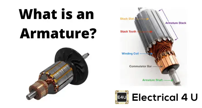
Armature Parts & Diagram
The armature is made up of a core, winding, commutator, and shaft. A diagram of an armature is shown below.
A diagram illustrating the parts of an armature
The parts of an armature are discussed in detail below.
Armature Core
The core of the armature is made up of laminated thin metal plates instead of a single piece. The thickness of laminations depends on the supply frequency. It is approximately 0.5mm thick. The laminated silicon steel is used for the armature core to reduce the eddy current and hysteresis loss.
Generally, the armature core is a hollow cylindrical shape. And the shaft is placed inside the armature core.
The core consists of the number of slots. The armature winding is placed in the slots provided on the outer surface of the armature core. The slots in the armature core are skewed at some angle to avoid magnetic locking and provides smooth rotation.
Armature Winding
The armature winding is inserted into slots of the armature core. The armature winding is insulated to avoid direct contact of the coil with the core. Generally, the winding is made up of copper. But in some cases, it is made up of aluminum to reduce the cost of the machine. According to the design of the armature winding, it can be lap wound or wave wound.
In a lap winding arrangement, the number of current paths is equal to the number of poles and brushes. In this type of winding, the finishing end of one coil is connected to the commutator segment and the starting end of the next coil is connected at the same pole and commutator segment.
In a wave winding arrangement, the number of current paths is only two. In this type of winding, both ends of each coil are connected to the commutator segment with the distance between the poles. This makes a series connection of coils and the addition of voltages in winding between brushes.
To learn more about these armature winding arrangements, learn more about pole pitch and coil span.
Shaft
The shaft of the machine is used to transfer mechanical energy. It is a stiff rod mounted between two bearings. The length, speed, and bearing points are decided to minimize the harmonic distortions. The thickness of the shaft is chosen enough to transmit the torque required by the machine. and it must be stiff enough to control any out of balance forces.
Commutator
The commutator is made up of copper bars, each bar is separated from each other with the help of insulating materials like mica or plastic.
It is pressed onto the shaft and wires from each coil come out of the slots and connect to the commutator bars. When the commutator is pressed on the shaft, it must be aligned precisely with the slot.
The armature must be placed with exact angular displacement from the commutator bar to work efficiently for the magnetic circuit.
What Makes the Armature in an Electric Motor Rotate?
The electric motors are used to convert electrical energy into mechanical energy. Generally, the armature is a rotating part of a machine.
A current-carrying conductor experience force when it placed in the magnetic field and the direction of force is given by Fleming’s left-hand rule.
When the supply is given to the stator, the rotating magnetic field is induced in the motor. This rotating magnetic field exerts a force on the armature (rotor) and the armature rotates. This is sometimes referred to as the armature reaction of a synchronous motor.
How to Test an Armature?
If the armature is damaged, the motor will not run. So, we need to test an armature. To test the armature remove it from the motor.
Armature Test 1
First, we will check the armature winding. By this test, we can find if the armature winding is open-circuited or short-circuited.
In this test, we will measure the resistance of two commutator bars of each coil at 180˚ across each other with the help of ohmmeter. The reading of the ohmmeter depends on the size of the motor. But in this condition, we are not interested in the exact reading.
After testing one reading, rotate armature and check resistance between every pair of bars on the commutator.
If the reading is the same for all pairs, the armature winding is good. And if the reading is decreasing towards zero, the armature winding is short-circuited. Similarly, if the reading is increasing towards infinite, the armature winding is broken or open-circuited.
Armature Test 2
We need to find; which winding is damaged. So, for that, we need to measure the resistance of each bar. Similar to test-1, if the readings are the same for all bars, the winding is good. And if you find a drastic change in the resistance, the winding is damaged.
Armature Test 3
In this test, we will measure the resistance of every commutator bar with the armature stack. In this test, the commutator bars must not have electrical continuity to the armature stack.


![Toni Kroos là ai? [ sự thật về tiểu sử đầy đủ Toni Kroos ]](https://evbn.org/wp-content/uploads/New-Project-6635-1671934592.jpg)


