
The Structure of Electric Power Systems (Generation, Distribution and Transmission Of Energy) | EEP
Mục Lục
What is the electric power system?
From a general perspective, an electric power system is usually understood as a very large network that links power plants (large or small) to loads, by means of an electric grid that may span a whole continent, such as Europe or North America.

A power system thus typically extends from a power plant right up to the sockets inside customers’ premises. These are sometimes referred to as full power systems as they are autonomous.
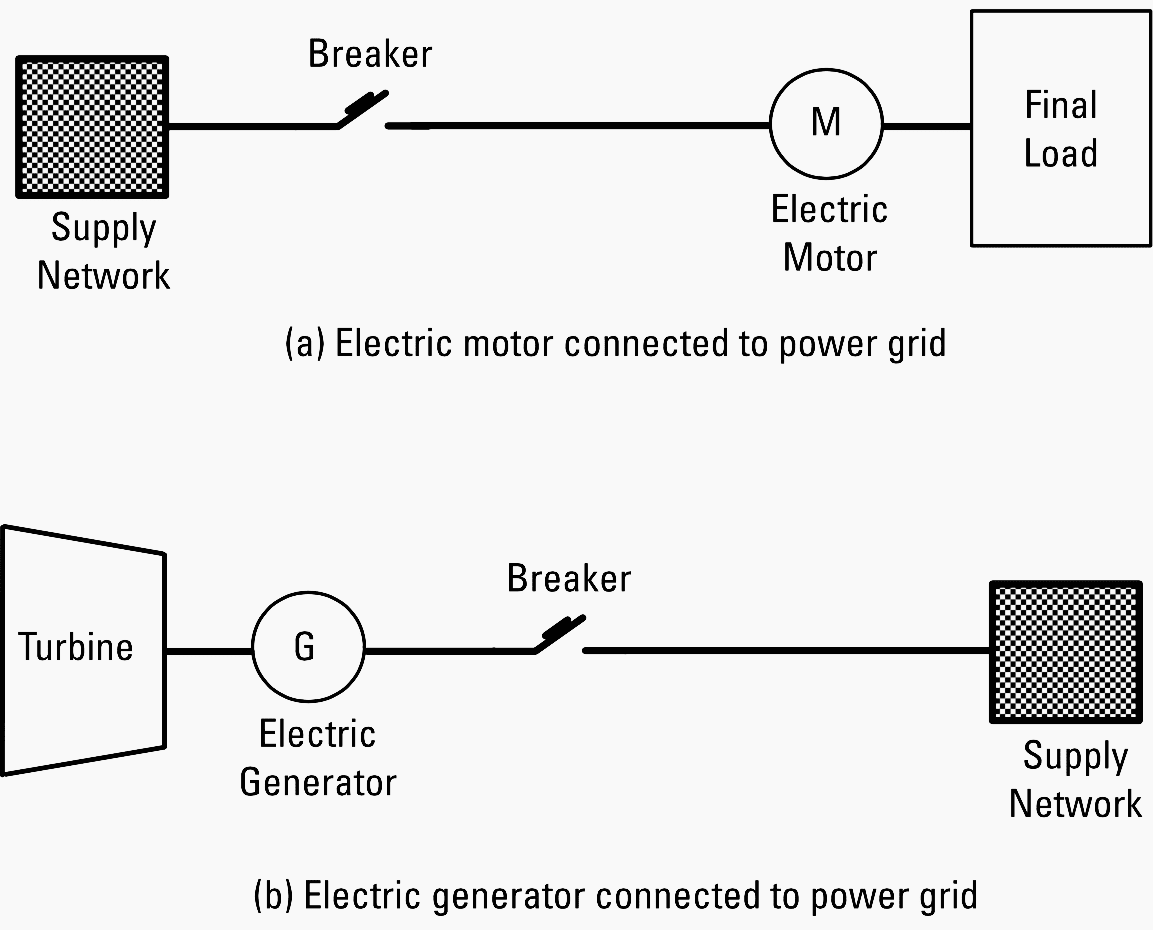
Smaller power systems could be made of part or sections of a larger, full system. Figure 1 shows several elements that operate together and are connected to a power supplying network.
final user of the electric energy of a full power system. The subsystem represented in Figure 1(b) could be one of a small power plant working as
The subsystem represented in Figure 1(a) could be one of a. The subsystem represented in Figure 1(b) could be one of a small power plant working as distributed generation (DG) . Most of these power systems operate only when connected to a full power system.
Power systems that are supplied by an external electricity source or that produce (by conversion from other sources) electricity and convey it to a larger grid are called partial power systems.
The power systems that are of interest for our purposes are the large scale, full power systems that span large distances and have been deployed over decades by power companies.
Generation is the production of electricity at power stations or generating units where a form of primary energy is converted into electricity. Transmission is the network that moves power from one part of a country or a region to another. It is usually a well-interconnected infrastructure in which multiple power lines link different substations, which change voltage levels, offering enhanced redundancy.
Distribution finally delivers the power (we could say locally when compared to the transmission system) to the final loads (a majority of which are supplied at low voltage) via intermediate steps at which the voltage is converted down (transformed) to lower levels.
The distribution system ends up at the energy consumption points or loads where power is used for its final purpose.
There are parts of the world in which the deregulation and privatization of the industry has already completely changed the industry landscape, while in others the impact is still to be seen.
Power Generation
Power plants convert the energy stored in the fuel (mainly coal, oil, natural gas, enriched uranium) or renewable energies (water, wind, solar) into electric energy.
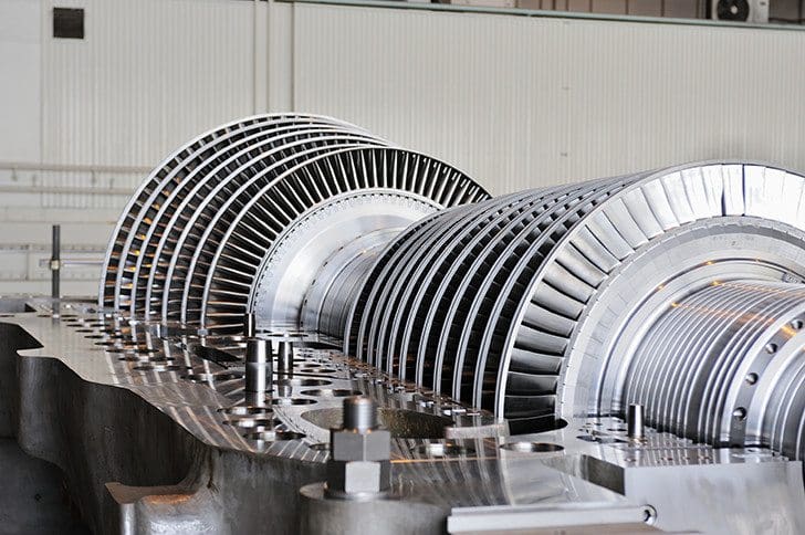
Conventional modern generators produce electricity at a frequency that is a multiple of the rotation speed of the machine. Voltage is usually no more than 6 to 40 kV. The power output is determined by the amount of steam driving the turbine, which depends mainly on the boiler. The voltage of that power is determined by the current in the rotating winding (i.e., the rotor) of the synchronous generator.
The output is taken from the fixed winding (i.e., the stator). The voltage is stepped up by a transformer, normally to a much higher voltage. At that high voltage, the generator connects to the grid in a substation.
Traditional power plants generate ac power from synchronous generators that provide three-phase electric power, such that the voltage source is actually a combination of three ac voltage sources derived from the generator with their respective voltage phasors separated by phase angles of 120°.
Wind turbines and mini hydro units normally employ asynchronous generators, in which the waveform of the generated voltage is not necessarily synchronized with the rotation of the generator.
DG refers to generation that connects into the distribution system, as opposed to conventional centralized power generation systems.
The Electric Power Research Institute (EPRI) has defined distributed generation as the “utilization of small (0 to 5 MW), modular power generation technologies dispersed throughout a utility’s distribution system in order to reduce T&D loading or load growth and thereby defer the upgrade of T&D facilities, reduce system losses, improve power quality, and reliability.”
Small generators are constantly improving in terms of cost and efficiency, becoming closer to the performance of large power plants.
How does a Thermal power plant work?
Transmission Systems
Power from generation plants is carried first through transmission systems, which consist of transmission lines that carry electric power at various voltage levels. A transmission system corresponds to a networked, meshed topology infrastructure, connecting generation and substations together into a grid that usually is defined at 100 kV or more.
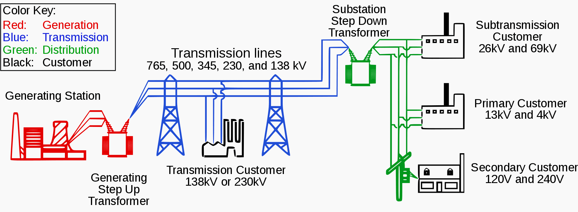
The electricity flows over high-voltage (HV) transmission lines to a series of substations where the voltage is stepped down by transformers to levels appropriate for distribution systems.
AC rms voltage levels
Preferred AC rms voltage levels are internationally standardized in IEC 60038:2009 as:
- 362 kV or 420 kV; 420 kV or 550 kV; 800 kV; 1,100 kV or 1,200 kV highest voltages for three-phase systems having a highest voltage for equipment exceeding 245 kV.
- 66 (alternatively, 69) kV; 110 (alternatively, 115) kV or 132 (alternatively, 138) kV; 220 (alternatively, 230) kV nominal voltages for three- phase systems having a nominal voltage above 35 kV and not exceeding 230 kV.
- 11 (alternatively, 10) kV; 22 (alternatively, 20) kV; 33 (alternatively, 30) kV or 35 kV nominal voltages for three-phase systems having a nominal voltage above 1 kV and not exceeding 35 kV. There is a separate set of values specific for North American practice.
In the case of systems having a nominal voltage between 100V and 1,000V inclusive, 230/400V is standard for three-phase, four-wire systems (50 Hz or 60 Hz) and also 120/208V for 60 Hz. For three-wire systems, 230V between phases is standard for 50 Hz and 240V for 60 Hz. For single-phase three-wire systems at 60 Hz, 120/240V is standard.
Medium voltage (MV) as a concept is not used in some countries (e.g., United Kingdom and Australia), it is “any set of voltage levels lying between low and high voltage” and the problem to define it is that the actual boundary between MV and HV levels depends on local practices.
In Europe, overhead transmission lines are used in open areas such as interconnections between cities or along wide roads within the city. In congested areas within cities, underground cables are used for electric energy transmission. The underground transmission system is environmentally preferable but has a significantly higher cost.
Transmission lines are deployed with three wires along with a ground wire. Virtually all ac transmission systems are three-phase transmission systems.
Distribution Systems
Distribution segment is widely recognized as the most challenging part of the smart grid due to its ubiquity. Voltage levels of 132 (110 in some places) or 66 kV are usual HV levels that can be found in (European) distribution networks. Voltages below that (e.g., 30, 20, 10 kV) are commonly found in MV distribution networks.
Distribution levels below 1 kV are within what is known as LV or Low Voltage.
MV grid topologies can be classified in three groups:
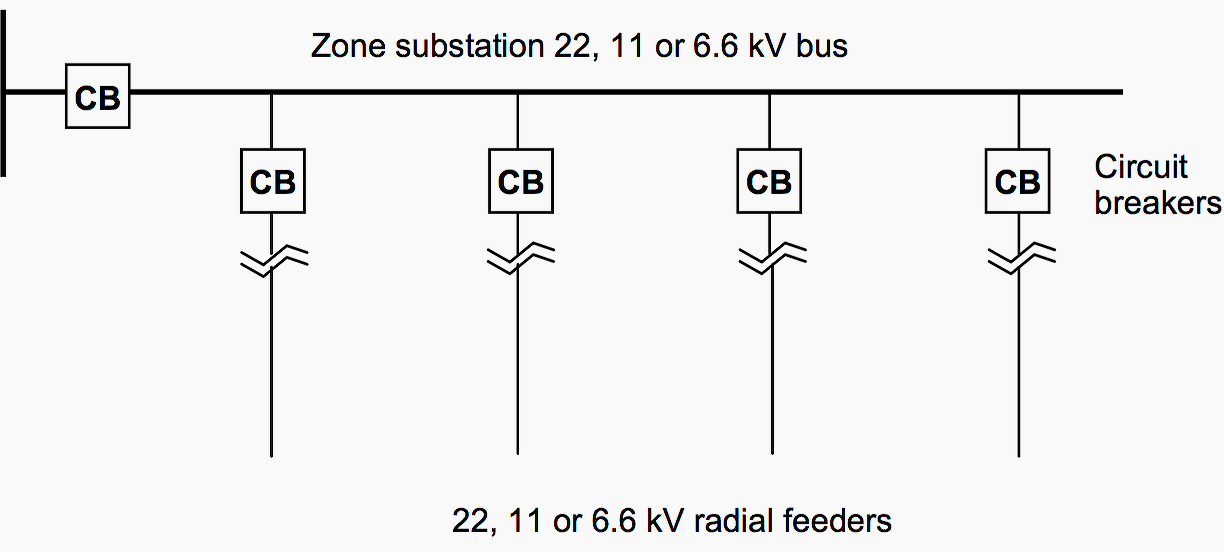
Radial topology
Radial lines are used to connect primary substations (PSs) with secondary substations (SSs), and the SSs among them. These MV lines or “feeders” can be used exclusively for one SS or can be used to reach several of them. Radial systems keep central control of all the SSs.
These radial topologies show a tree-shaped configuration when they grow in complexity. They are a less expensive topology to develop, operate, and maintain, but they are also less reliable.
Ring topology
This is a fault-tolerant topology to overcome the weakness of radial topology when there is a disconnection of one element of the MV line that interrupts electricity service (outage) in the rest of the connected substations. A ring topology is an improved evolution of the radial topology, connecting substations to other MV lines to create redundancy.
Independently of the physical configuration, the grid is operated radially, but on the event of a failure in a feeder, other elements are maneuvered to reconfigure the grid in such a way that outages are avoided.

Networked topology
Networked topology consists of primary and secondary substations connected through multiple MV lines to provide a variety of distribution alternatives. Thus, the reconfiguration options to overcome faults are multiple, and in the event of failure, alternative solutions may be found to reroute electricity.
LV distribution systems can be single-phase or three-phase. In Europe, for example, they are usually three-phase, 230V/400V systems (i.e., each phase has an rms voltage of 230V and the rms voltage between two phases is 400V).
LV grids present more complex and heterogeneous topologies than MV grids. The exact topology of LV systems depends on the extension and specific features of the service area, the type, number and density of points of supply (loads), country-specific and utility-specific operating procedures, and range of options in international standards.

An SS typically supplies electricity to one or several LV lines, with one or multiple MV-to-LV transformers at the same site. LV topology is typically radial, having multiple branches that connect to extended feeders, but there are also cases of networked grids and even ring or dual-fed configurations in LV networks.
LV lines are typically shorter than MV lines, and their characteristics are different depending on the service area.
Reference // Telecommunication Networks for the Smart Grid by Alberto Sendin (Purchase hardcover from Amazon)


![Toni Kroos là ai? [ sự thật về tiểu sử đầy đủ Toni Kroos ]](https://evbn.org/wp-content/uploads/New-Project-6635-1671934592.jpg)


