
The essentials of electrical distribution systems every engineer should know | EEP
Mục Lục
Transfering AC/DC electrical power
Electrical distribution systems are an essential part of the electrical power system. In order to transfer electrical power from an alternating current (AC) or a direct current (DC) source to the place where it will be used, some type of distribution network must be utilized.

The method used to distribute power from where it is produced to where it is used can be quite simple. More complex power distribution systems are used, to transfer electrical power from the power plant to industries, homes, and commercial buildings.
Contents:
1. Distribution systems in general
Distribution systems usually employ such equipment as transformers, circuit breakers, and protective devices. The original electrical distribution system developed by Thomas Edison was an underground direct current (DC) system.
In general, the distribution system is the electrical system between the substation fed by the transmission system and the consumer end.
It generally consists of feeders, distributors. The single line diagram of a typical distribution system is shown in Figure 1.
Basically we can say, that part of power system which distributes electric power for local use is known as distribution system.
Feeders
A feeder is a conductor which connects the substation (or localized generating station) to the area where power is to be distributed. Generally, no tappings are taken from the feeder so that current in it remains the same throughout (Figure 2).
The main consideration in the design of a feeder is the current carrying capacity.
Distributor
A distributor is a conductor from which tappings are taken for supply to the consumers. The current through a distributor is not constant because tappings are taken at various places along its length.
Service mains
A service maim is generally a small cable which connects the distributor to the consumers’ terminals.
Go back to contents ↑
2. Classification
A distribution system may be classified according to:
According to nature of current, distribution system may be classified as:
- Direct current (DC) distribution system
- Alternative current (AC) distribution system.
Now-a-days, AC system is universally adopted for distribution of electric power as it is simpler and more economical than direct current method.
According to scheme of connection, the distribution system may be classified as:
- Radial system
- Ring main system
- Inter-connected system.
Each scheme has its own advantages and disadvantages.
Go back to contents ↑
2.1 AC distribution
Now-a-days electrical energy is generated, transmitted and distributed in the form of alternating current. One important reason for the widespread use of alternating current in preference to direct current is the fact that alternating voltage can be conveniently changed in magnitude by means of a transformer.
Transformer has made it possible to transmit ac. power at high voltage and utilize it at a safe potential. High transmission and distribution voltages have greatly reduced the current in the conductors and the resulting line losses.
There is no definite line between transmission and distribution according to voltage or bulk capacity. This line also vary from country to country.
However, in general, the AC distribution system is the electrical system between the step-down substation fed by the transmission system and the consumers’ meters (Figure 3).
The AC distribution system is classified into:
- Primary distribution system and
- Secondary distribution system.
Go back to contents ↑
2.1.1 Primary distribution system
It is that part of AC distribution system which operates at voltages somewhat higher than general utilization and handles large blocks of electrical energy than the average low-voltage consumer uses (Figure 4).
The voltage used for primary distribution depends upon the amount of power to be conveyed and the distance of the substation required to be fed. The most commonly used primary distribution voltages are 11 kV, 66 kV and 33 kV, but this differs from country to country.
One to economic considerations, primary distribution is carried out by 3-phase, 3-wire system.
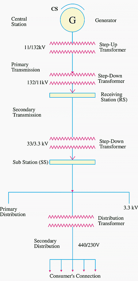
Electric power from the generating station is transmitted at high voltage to the substation located in or near the city. At this substation, voltage is stepped down to 11 kV with the help of step-down transformer.
Power is supplied to various substations for distribution or to big consumers at this voltage. This forms the high voltage distribution or primary distribution.

Go back to contents ↑
2.1.2 Secondary distribution system
It is that part of AC distribution system which includes the range of voltages at which the ultimate consumer utilizes the electrical energy delivered to him.
The secondary distribution employs 400/230 V, 3-phase, 4-wire system. The primary distribution circuit delivers power to various substations, called distribution substations.
The substations are situated near the consumers’ localities and contain step-down transformers. At each distribution substation, the voltage is stepped down to 400 V and power is delivered by 3-phase, 4-wire system.
The voltage between any two phases is 400 V and between any phase and neutral is 230 V (Figure 5).
The single phase domestic loads are connected between any one phase and the neutral, whereas 3-phase 400 V motor, power transformer loads are connected across 3-phase lines directly.

Go back to contents ↑
2.2 DC distribution
It is a common knowledge that electric power is almost exclusively generated, transmitted and distributed as AC However, for certain applications, DC supply is absolutely necessary.
For instance, DC supply is required for the operation of variable speed machinery (i.e., DC motors), for electro-chemical work and for congested areas where storage battery reserves are necessary.
For this purpose, AC power is converted into DC power at the substation by using converting machinery e.g., mercury arc rectifiers, rotary converters and motor-generator sets.
The DC supply hum the substation may be obtained in the form of:
- 2-wire or
- 3-wire for distribution
Go back to contents ↑
2.2.1 2-wire DC system
As the name implies, this system of distribution consists of two wires (+ and -). One is the outgoing or positive wire and the other is the return or negative wire. The loads such as lamps, motors etc. are connected in parallel between the two wires.
This system is never used for transmission purposes due to low efficiency but may be employed for distribution of DC power.
Go back to contents ↑
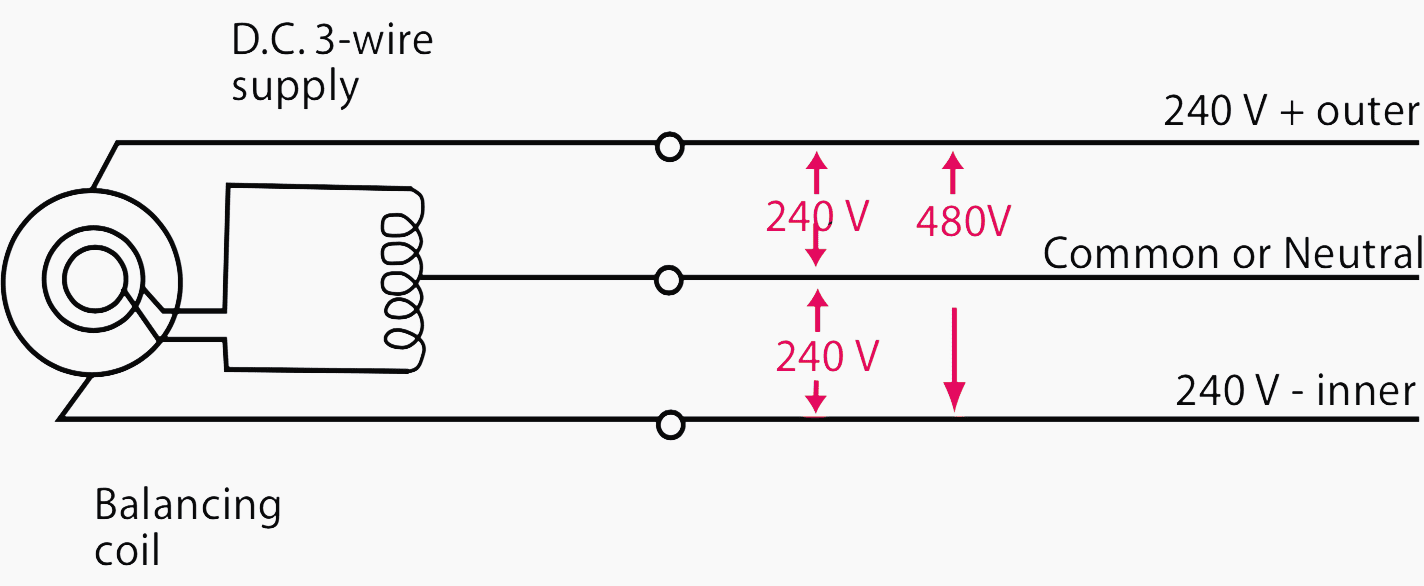
2.2.2 3-wire DC system
It consists of two outer and a middle or neutral wire which is earthed at the substation (see Figure 5). The voltage between the outers is twice the voltage between either outer and neutral wire.
The principal advantage of this system is that it makes available two voltages at the consumer terminals between any outer and the neutral and between the outers.
Loads requiring high voltage (e.g., motors) are connected across the outers, whereas lamps and heating circuits requiring less voltage are connected between either outer and the neutral.
Go back to contents ↑
2.3 Most common distribution arrangements
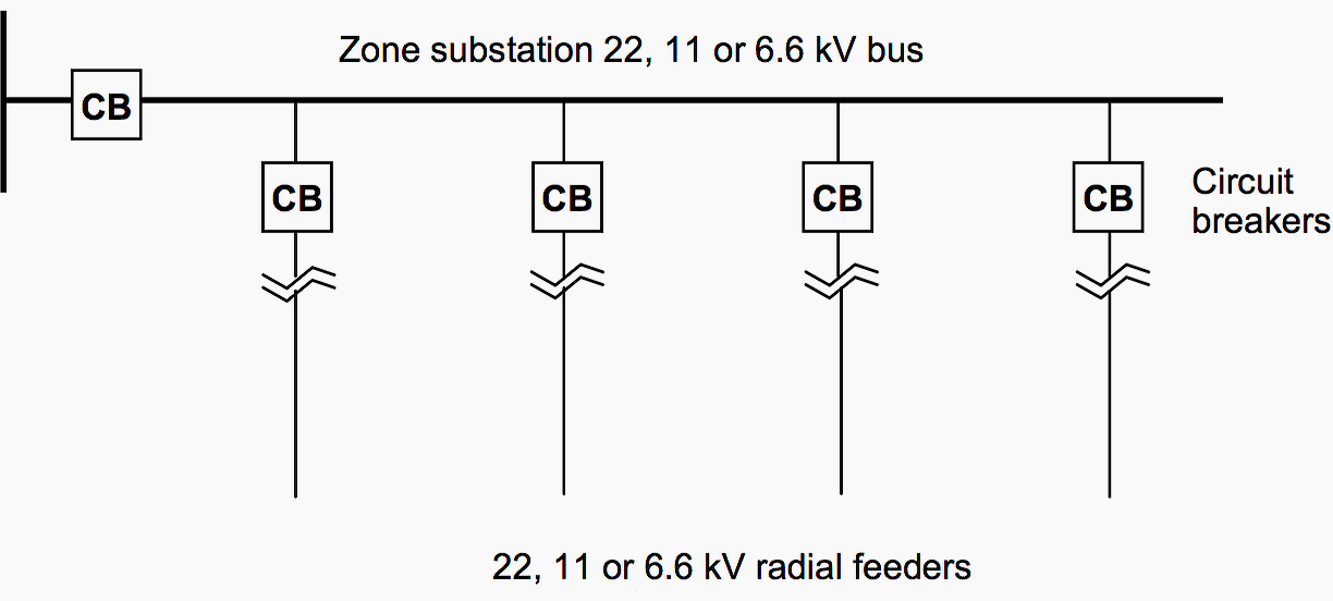
2.3.1 Radial System
In this system, separate feeders radiate from a single substation and feed the distributors at one end only. A single line diagram of a radial distribution system is shown in Figure 6. The radial system is employed at low voltage and the substation is located at the center of the load.
This is the simplest distribution circuit and has the lowest initial cost.

However, it suffers from the following drawbacks.
- The end of the distributor nearest to the feeding point will be heavily loaded.
- The consumers are dependent on a single feeder and single distributor.
Therefore, any fault on the feeder or distributor cuts off supply to the consumers who are on the side of the fault away from the substation.
- The consumers at the distant end of the distributor would be subjected to serious voltage fluctuations when the load on the distributor changes.
Due to these limitations, this system is used for short distances only. The radial system can be extended by introducing more laterals and sub-laterals.
Go back to contents ↑
2.3.2 Ring main system
In this system, the primaries of distribution transformers form a loop. The loop circuit starts from the substation bus-bars, makes a loop through the area to be served, and returns to the substation.
The single line diagram of ring main system is shown in Figure 7.
The ring main system has the following advantages:
- There are less voltage fluctuations at consumer’s terminals.
- The system is very reliable as each distributor is fed via two feeders. In the event of fault on any section of the feeder, the continuity of supply is maintained.
For example, suppose that fault occurs at any section of the feeder. Then the faulted section the feeder can be isolated for repairs and at the same time continuity of supply is maintained to all the consumers via the other feeder.
Go back to contents ↑
2.3.3 Interconnected power systems
When the feeder ring is energized by two or more than two source, it is called interconnected system. The single line diagram of interconnected system is shown in Figure 8 below.
The interconnected system has the following advantages:
- It increases the service reliability.
- Any area fed from one generating station during peak load hours can be fed from the other generating station. This reduces reserve power capacity and increases efficiency of the system.
Go back to contents ↑
3. Voltage drop calculation in DC system
The voltage drop in distribution system is calculated by following Ohm,s Law. Let us consider a simple do radial distribution system as shown in Figure 9.

The system have concentrated load Ia, Ib, Ic, Id and Ie at load point A,B,C,D and E respectively. The resistance of different section has been shown in the Figure 5 above.
The feeder is fed at point O. Let the voltages at different nodes are Va, Vb, Vc, Vd and Ve and the feeder is fed at the voltage Vo . Hence the voltage drop is given by:
VDTotal =VDOA + VDAB +VDBC + VDCD + VDDE
Current flowing in sections:
- The current flowing in the section ‘OA’ is: Ioa = Ia + Ib + Ic + Id + Ie
- The current flowing in the section ‘AB’ is: Iab = Ib + Ic + Id + Ie
- The current flowing in the section ‘BC’ is: Ibc = Ic + Id + Ie
- The current flowing in the section ‘CD’ is: Icd = Id + Ie
- The current flowing in the section ‘DE’ is: Ide = Ie
The total voltage drop therefore, is given by:
VDTotal = IoaRoa + IabRab + IbcRbc + IcdRcd + IdeRde
Similarly, we can determine the voltage drop for AC distribution system. In many cases the load in the system is not concentrated, it may be either uniform loading or a combination of uniform and concentrated loading.
If the load is uniform then the voltage drop is calculated for a very small length of the feeder such as dx and then integrate it over the whole length.
Go back to contents ↑
4. Requirements of a good distribution system
A considerable amount of effort is necessary to maintain an electric power supply within the requirements of various types of consumers. Some of the requirements of a good distribution system are:
- Proper voltage,
- Availability of power on demand and
- Reliability.
Proper voltage
One important requirement of a distribution system is that voltage variations at consumer’s terminals should be as low as possible. The changes in voltage are generally caused due to the variation of load on the system. Low voltage causes loss of revenue, inefficient lighting and possible burning out of motor.
High voltage causes lamps to burn out permanently and may cause failure of other appliances.
Therefore, a good distribution system should ensure that the voltage variations at consumer’s terminals are within permissible limits. The statutory limit of voltage variations is ± 5% of the rated value at the consumer’s terminals.
Thus, if the declared voltage is 230 V, then the highest voltage of the consumer should not exceed 242 V while the lowest voltage of the consumer should not be less than 218 V.
Availability of power on demand
Power must be available to the consumers in any amount that they may require from time to time. For example, motors may be started or shut down, lights may be turned on or off, without advance warning to the electric supply company. As electrical energy cannot be stored, therefore, the distribution system most be capable of supplying load demands of the consumers.
This necessitates that operating staff must continuously study load patterns to predict in advance those major load changes that follow the known schedules.
Reliability
Modern industry is almost dependent on electric power for its operation. Homes and office buildings are lighted, heated, cooled and ventilated by electric power. This calls for reliable service.
Unfortunately, electric power, like everything else that is man-made, can never be absolutely and 100% reliable.
However, the reliability can be improved to a considerable extent by:
- Interconnected system
- Reliable automatic control system
- Providing additional reserve facilities.
Go back to contents ↑
5. Design considerations
Good voltage regulation of a distribution network is probably the most important factor responsible for delivering good service to the consumers. For this purpose, design of feeders and distributors requires careful consideration.
Feeders
A feeder is designed from the point of view of its current carrying capacity while the voltage drop consideration is relatively unimportant. It is because voltage drop in a feeder can be compensated by means of voltage regulating equipment at the substation.
Distributors
A distributor is designed from the point of view of the voltage drop in it. It is because a distributor supplies power to the consumers and there is a statutory limit of voltage variations at the consumer’s terminals (±6% of rated value).
The size and length of the distributor should be such that voltage at the consumer’s terminals is within the permissible limits.
Go back to contents ↑
Reference // Class notes on electrical power transmission and distribution by Department of Electrical Engineering ; Veer Surendra Sai University of Technology; Burla


![Toni Kroos là ai? [ sự thật về tiểu sử đầy đủ Toni Kroos ]](https://evbn.org/wp-content/uploads/New-Project-6635-1671934592.jpg)


