Stick / SMAW Welding Tips & Techniques – Weld Guru
Affiliate Disclaimer: This post may contain links that will earn us a commission at no cost to you. This helps keep Weldguru a free resource for our readers.
Shielded Metal Arc Welding (SMAW) operation requires a setup and then weld.
In general, the operator factor, or the percentage of the operator’s time spent laying weld, is approximately 25%. The rest is spent in preparation and in removing slag.
The actual welding technique utilized depends on the electrode, the composition of the workpiece, and the position of the joint being welded.
The choice of electrode and welding position also determines the welding speed.
Flat welds require the least operator skill and can be done with electrodes that melt quickly but solidify slowly. This permits higher welding speeds.
Sloped, vertical or upside-down welding requires more operator skill and often necessitates the use of an electrode that solidifies quickly to prevent the molten metal from flowing out of the weld pool.
However, this generally means that the electrode melts less quickly, thus increasing the time required to lay the weld.
SMAW Operation Set-up
Before starting make sure that you are using a good helmet for SMAW welding as well as protective clothing.
- Clean the workpiece
- Clamp the work close to the weld
- Insert the electrode into the insulated holder holder. Set amperage at levels recommended by the electrode manufacturer.
- Determine the best arc length. As a guideline the arc for a 1/16″ to 3/32″ diameter electrode is 1/16″ (1.6mm). The arc lengh for a 1/8″ and 5/32″ electrode is 1/8″ (3mm).
- Have a chipping hammer available to remove any slag and before doing a 2nd pass with the weld.
Mục Lục
Stick Welding Examples
Operation
Starting the Arc
Scratch Start Technique:
To strike the electric arc when starting a SMAW operation, the electrode is brought into contact with the workpiece, dragged like lighting a match, and then pulled away slightly. If the arc lights and then goes out, that means the electrode was pulled too far away from the base metal. If the electrode sticks to the metal, give a twist and it should come free.
Tapping Technique:
Move the electrode straight down to the base metal. Then lift slightly. The arc should start. If the arc goes out, that means it was lifted too high off the workpiece.
Operating the Electrode Holder
This initiates the melting of the workpiece and the consumable electrode and causes droplets of the electrode to be passed from the electrode to the weld pool.
As the electrode melts, the flux covering disintegrates, giving off a vapor that protects the weld area from oxygen and other atmospheric gases.
In addition, the flux provides molten slag which covers the filler metal as it travels from the electrode to the weld pool.
Once part of the weld pool, the slag floats to the surface and protects the weld from contamination as it solidifies.
Groove (Butt) Joint Welding
Tack Welds
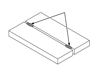
Tack weld the two pieces of metal to hold them in place. This will reduce joint distortion, which is caused by the expansion and contraction of metal as it is heated and cooled.
Related read: What is the purpose of a tack weld?
Double V-Groove, Single V-Groove & Square Groove Welds
When performing a groove weld, hold the electrode perpendicular to the weld. Lean the electrode in the direction of the weld.
A single string bead is all that is needed for a narrow groove weld joint. For wider groove weld, then a weave bead or many stringer beads is a better option.
Related Read: Types of Weld Beads: Stringer & Groove
Square Groove Weld


If the thickness of materials is 3/16″ (5MM) they can usually be welded with a square groove weld and no prep.
Single and Double V-Groove Welds
V-Groove
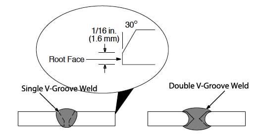
For SMAW operation welds that require thicker metals, it may require that edges are prepared (v-groove) of butt joints for good welds.
V-groove is recommended for metal thickness of 3/16″ to 3/4″ (5 to 19mm). It is also used for any thickness when welding can only be done from one side.
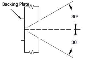
The bevel can be created (at 30 degrees) using a grinder, or plasma or oxyacetylene cutting equipment. After creating the bevel remove scale.
Related Stick Welding Read: Best machines for stick welding
T-Joint Welding
Fillet Weld

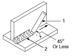
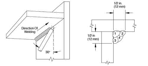
For a fillet weld, hold the electrode at a 45-degree angle or less to the weld. Lean the electrode 10 degrees to 30 degrees in the direction of the weld.
Use a short arc and move at a steady speed. For upright sections weld both sides.
When necessary for strength add a second layer (remove slag before adding another layer).
Move the electrode using a circular motion.
Single Layer Fillet Weld
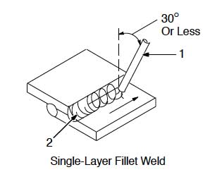
When welding a lap joint the electrode should be held at a 30-degree angle or less. Use one or two weld passes as needed. Before the second pass remove any slag.
Welding Positions
Each welding position is described below. Note that not every electrode is right for each position. Check the manufacturer’s directions before proceeding with any SMAW operation.
Horizontal
Single Pass Bead Weld
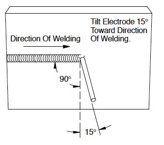
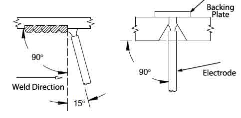
The issue with horizontal welding is the distorting effect gravity will have on the weld pool. If necessary or if it will help, tack weld a backing strip. Beveled edges can also be of help.
When welding during the SMAW operation keeps the electrode at 90 degrees to the weld. Lean into the weld direction by 15 degrees.
Materials Beveled For Horizontal Weld
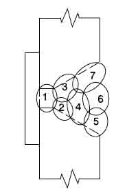
Multi-Pass Weld Locations

Vertical Welding Position
Multi-Pass Vertical Weld Diagram
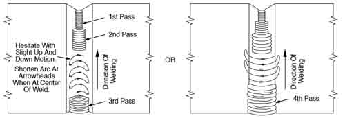
The weld direction can move from top to bottom or bottom to top. It is easier to weld in an upward direction.
Use a tack welded backing plate if needed and for thicker materials bevel the edges.
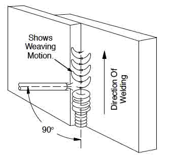
Hold the electrode at 90 degrees to the material being welding.
Vertical Tee Joint Welding Diagram
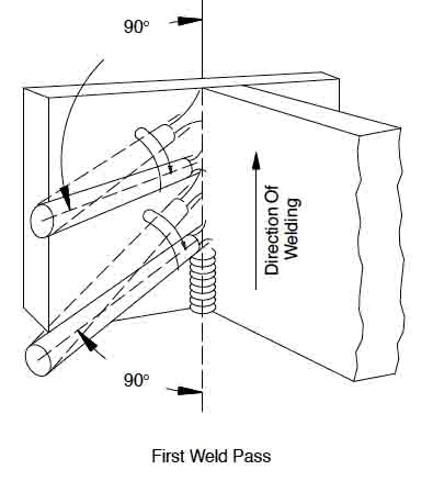
Lap Joint Weld Diagram
Overhead Welding Position
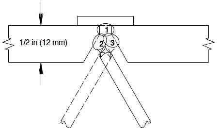
For an overhead weld the arc should be positioned slightly away an dout from the crater. Tack weld a backing plate and use beveled edges if necessary.
Overhead Groove Joint Diagram
Overhead Tee Joint
Testing the Weld
Weld Strength Test Diagram
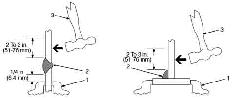
Use a hammer to strike the joint on the material welded to the base. The weld should bend slightly and not break.
Breakage could be due to too many holes (porous) in the weld, or if the weld contains slag.
Also note if any of the beveled area is visible.
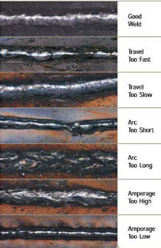
If it is, this could indicate that the filler material was not fully melted due to traveling too fast with the electrode or by not using enough heat.
Slag Removal
Once hardened, it must be chipped away to reveal the finished weld.
As welding progresses and the electrode melts, the welder must periodically stop welding to remove the remaining electrode stub and insert a new electrode into the electrode holder.
This activity, combined with chipping away the slag, reduce the amount of time that the welder can spend laying the weld, making SMAW one of the least efficient welding processes.


![Toni Kroos là ai? [ sự thật về tiểu sử đầy đủ Toni Kroos ]](https://evbn.org/wp-content/uploads/New-Project-6635-1671934592.jpg)


