Electric Generator Class 10 – Working, Principle, Diagram – Teachoo
Mục Lục
What is an electric generator?
An electric generator is a device which converts mechanical energy into electrical energy.
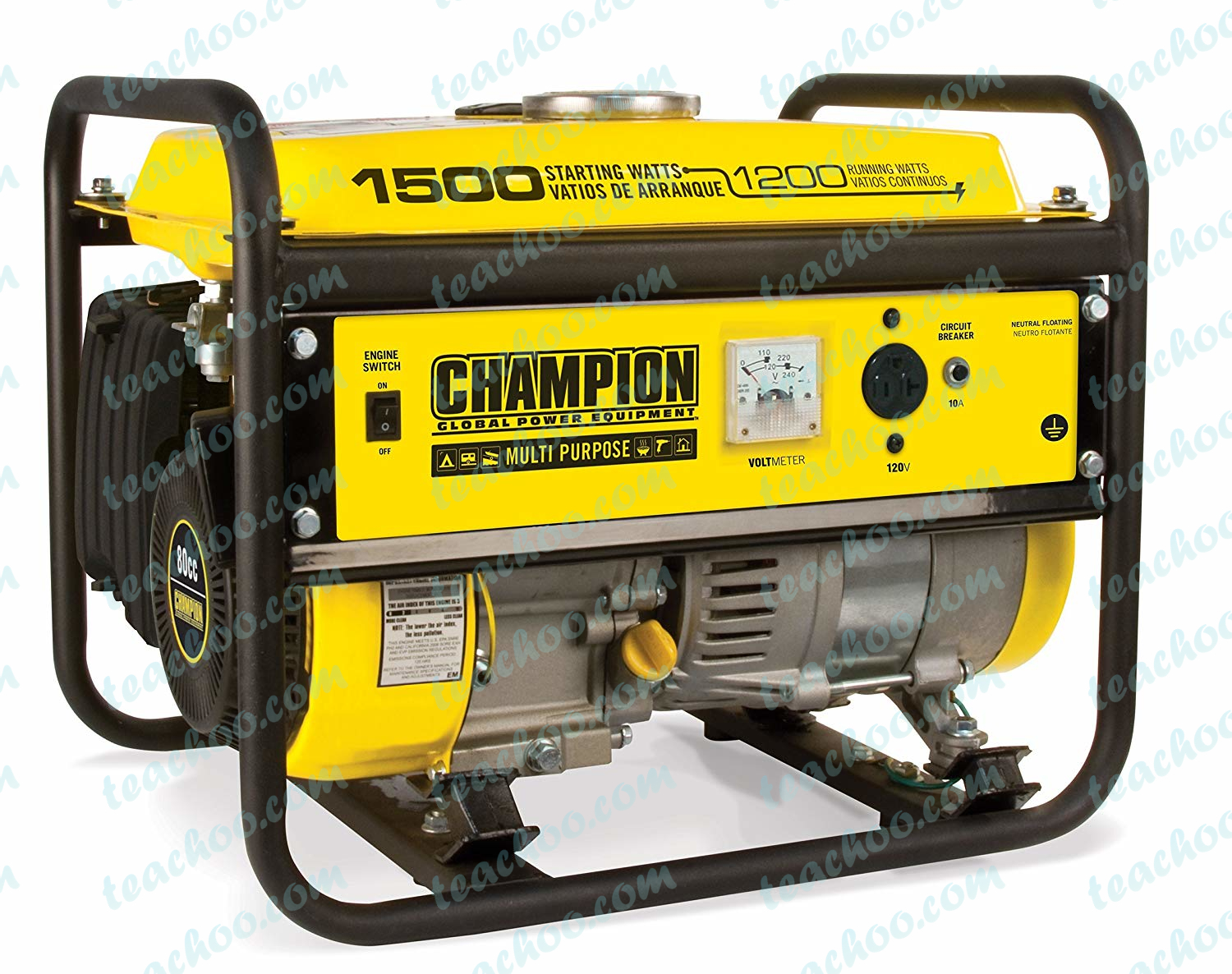
It looks like

Principle of Electrical generator
The electrical generator works on the principle that
when a straight conductor is moved in a magnetic field,
then current is induced in the conductor.
Types of Generators
Generator is used to generate electric current.
The electric current can be – AC current or DC current.
Thus, Electric Generators is of two types
-
AC Generator
– Generates Alternating Current (AC current) -
DC Generator
– Generates Direct Current (DC current)
Note
: Whenever Electric Generator is mentioned, we will assume it is a AC Generator
Construction of an AC Electric Generator

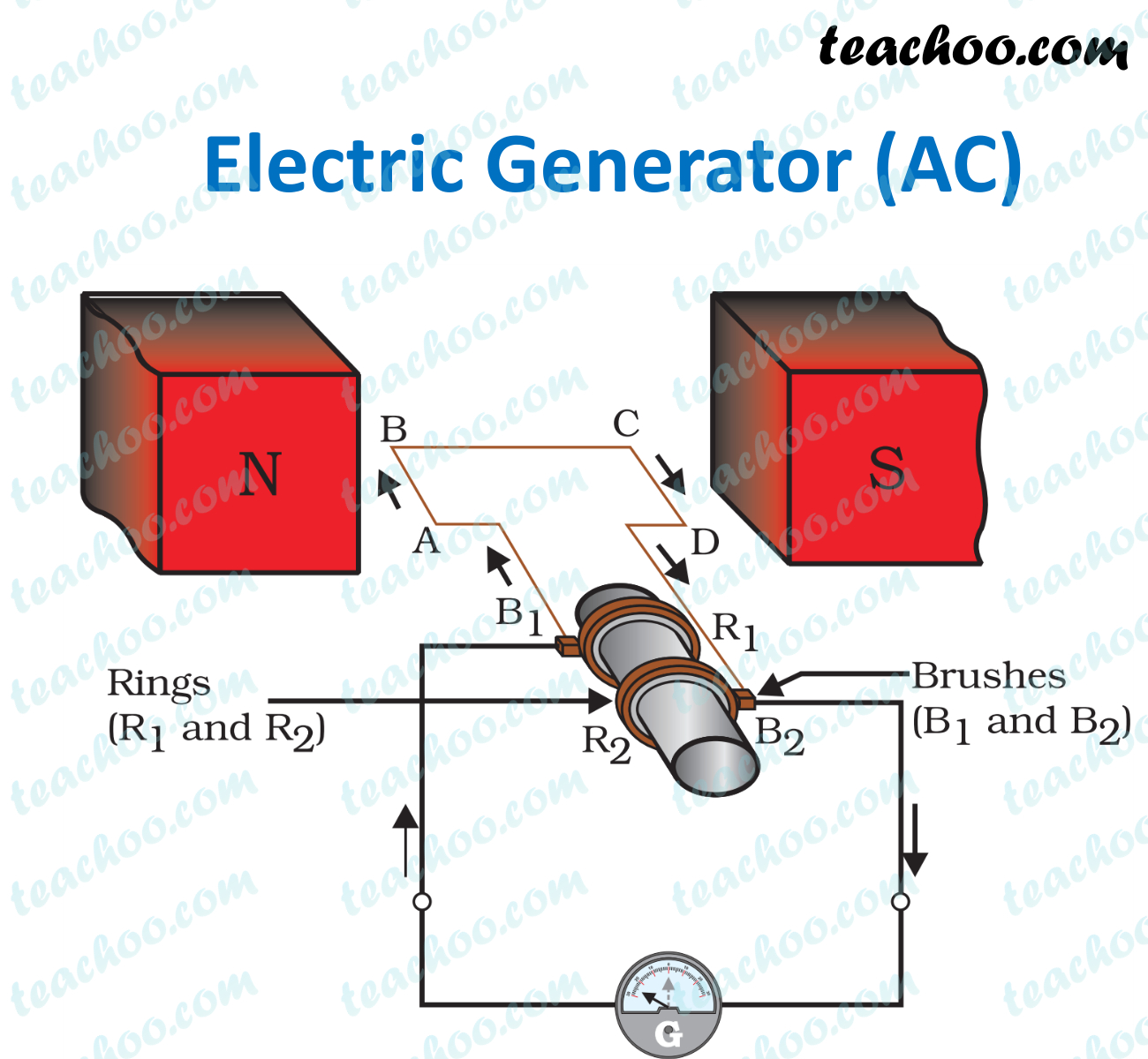
AC Electric Generator consists of
-
Rectangular Coil
of Wire ABCD -
A
strong horseshoe magnet
(or 2 different magnets ) – If we take 2 magnets, North Pole of first magnet faces South Pole of Other Magnet, as shown in figure… -
The
coil is placed perpendicular to the magnet
as shown in figure -
The ends of coil are connected to
two rings – R1
and R
2
-
The external conducting edges of rings R
1
and R
2
are connected to two
stationary brushes – B1
& B
2
respectively -
The inner side of the rings is
insulated and attached to the axle
The
axle is mechanically rotated
to rotate the coil -
These brushes are attached to a
galvanometer
to show the flow of current in the circuit
Working of an AC Electric Generator
Let’s look at the working of an AC Electric Generator
-
Suppose axle is rotated clockwise, so coil is also rotated clockwise,
Side AB of Coil moves up and side CD Moves down
Applying
Fleming’s Right Hand Rule
on side
AB,
force is upwards, magnetic field is left to right,
So,
current flows
into the paper i.e. from
A to B
-
And applying
Fleming’s Right Hand Rule
on side
CD,
force is downwards, magnetic field is left to right,
So,
current flows
out of the paper i.e. from
C to D
-
Hence, current flows into the Brush B
2
, moves along galvanometer and finally enters B
1
Hence, we say current flows from
B2
to B
1
in the external circuit.
-
After
half a rotation,
Side CD Comes on left side and AB Comes on Right Side -
Now, on left side CD comes down,
Applying
Fleming’s Right Hand Rule
on side
CD,
force is downwards, magnetic field is left to right,
So,
current flows
out of the paper i.e. from
D to C
-
And on right side, AB comes up,
Applying
Fleming’s Right Hand Rule
on side
AB,
force is upwards, magnetic field is left to right,
So,
current flows
into the paper i.e. from
A to B -
Hence, our circuit is now DCBA,
and current moves in the
opposite direction

-
Hence, we say current flows from
B1
to B
2
in the external circuit.
-
Thus, after every half rotation, direction of current changes.
Hence, Alternating Current is produced
Now, lets look at DC Generator – where current is in one direction
Note: To convert AC generator to DC Generator, we use a
commutator with split rings
(Split, not slip). Just like we do in an Electric Motor
Construction of DC Generator

DC Electric Generator consists of
-
Rectangular Coil
of Wire ABCD -
A
strong horseshoe magnet
(or 2 different magnets ) – If we take 2 magnets, North Pole of first magnet faces South Pole of Other Magnet, as shown in figure… -
The
coil is placed perpendicular to the magnet
as shown in figure -
The ends of coil are connected to a split ring commutator –
P and Q
-
The external conducting edges of rings P and Q are connected to two
stationary brushes – X & Y
respectively -
The inner side of the rings is
insulated and attached to the axle
The
axle is mechanically rotated
to rotate the coil -
These brushes are attached to a
galvanometer
to show the flow of current in the circuit
Working of a DC Electric Generator
Let’s look at the working of a DC Electric Generator
-
Suppose axle is rotated clockwise, so coil is also rotated clockwise,
Side AB of Coil moves up and side CD Moves down
Applying
Fleming’s Right Hand Rule
on side
AB,
force is upwards, magnetic field is left to right,
So,
current flows
into the paper i.e. from
A to B
-
And applying
Fleming’s Right Hand Rule
on side
CD,
force is downwards, magnetic field is left to right,
So,
current flows
out of the paper i.e. from
C to D
-
Hence, current flows into the Brush Y , moves along galvanometer and finally enters X
Hence, we say current flows from
Y to X in the external circuit.
-
After
half a rotation,
Side CD Comes on left side and AB Comes on Right Side -
And
Split ring P is connected to coil CD
and
split ring Q is connected to coil AB.
Which keeps the direction of current in the circuit same. -
Hence, current flows from Brush Y , moves along galvanometer and finally enters X
Hence, we say current flows from
Y to X in the external circuit. -
Thus, direction of current after every half rotation, direction of current changes.
Hence, Alternating Current is produced
How does Power Stations increase Current and Voltage produced?
They increase current and voltage produced by
- Using Electromagnet in place of permanent magnet
- Large number of turns of conducting wire(More the turns in wire more the magnetic field)
- Soft iron Core on which coil is wound
- Rotating the coil faster
Questions
NCERT Question 4 –
The essential difference between an AC generator and a DC generator is that
-
AC generator has an electromagnet while a DC generator has
permanent magnet.
-
DC generator will generate a higher voltage.
-
AC generator will generate a higher voltage.
-
AC generator has slip rings while the DC generator has a commutator.
View Answer
NCERT Question 6 (b)
–
State whether the following statements are true or false.
An electric generator works on the principle of electromagnetic induction.
View Answer
NCERT Question 16 –
The essential difference between an AC generator and a DC generator is that
View Answer
Question 1 Page 237 –
State the principle of an electric generator.
View Answer
Question 4 Page 237 –
A rectangular coil of copper wire is rotated in a magnetic field. The direction of the induced current changes once in each
(a) two revolutions (b) one revolution
(c) half revolution (d) one-fourth revolution
View Answer
Get live Maths 1-on-1 Classs – Class 6 to 12
Book 30 minute class for ₹ 499 ₹ 299


![Toni Kroos là ai? [ sự thật về tiểu sử đầy đủ Toni Kroos ]](https://evbn.org/wp-content/uploads/New-Project-6635-1671934592.jpg)


