
Electric Field Lines: Definition, Properties, and Drawings
Electric field lines or electric lines of force are imaginary lines drawn to represent the electric field visually. Since the electric field is a vector quantity, it has both magnitude and direction. Suppose one looks at the image below. The arrows indicate the electric field lines, and they point in the direction of the electric field. The significance of electric field lines is that they tell us how space is distorted by the presence of a charge or a distribution of charges.
English physicist Michael Faraday first developed the concept of electric field lines in the 1830s.
The electric field lines follow a specific pattern and configuration depending upon the distribution of electric charges. Since the electric field is a vector, it is represented by arrows drawn near the charges. The rules for drawing electric field lines follow the properties mentioned above.
For a Single Charge
For a single isolated charge, the lines are drawn differently for positive and negative charges, as shown in Figure 1. They are drawn such that they come out of a positive charge and terminate at infinity. On the other hand, the lines start from infinity and terminate at a negative charge. Such a direction is known as the radial direction. In other words, the lines are radially outward for a positive charge and radially inward for a negative charge.
The strength of charge also affects how the lines are drawn. A lower charge will have fewer lines surrounding it than a higher charge, as shown in Figure 2. Since the line density at any point indicates the strength of the electric field in that region, the closer the lines, the stronger is the field. The density is high near the charge and decreases as one moves further.
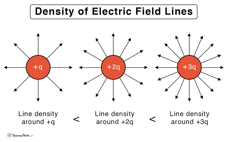 Figure 2 : Density of Electric Field Lines
For Two Isolated Point Charges
The presence of other charges will alter the path of electric field lines. In this case, the electric field will follow the principle of superposition. The magnitude and direction of the electric field at each location is simply the vector sum of the electric field vectors for each charge.
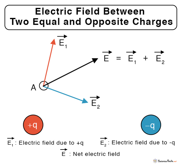
Let us take the simple case of two opposite charges of the same magnitude placed next to each other, as shown in Figure 3. The electric fields at point A due to charges +q and -q are E1 and E2, respectively. Therefore, the net electric field at A due to the charges is E = E1 + E2. Similarly, suppose other points in the region are chosen (not shown in the image for simplicity). The electric field at those points can be determined by this vectorial addition method.
 Electric Field Due to Two Point Charges
Once we know the electric field at different points, we can proceed to draw the field lines. Keep in mind that the electric field’s direction is tangential to the electric field line at that point (refer to property #6). The following image shows the field lines between (a) two equal and opposite charges and (b) two equal and like charges. It is evident from Figure 4 that opposite charges attract and like charges repel.
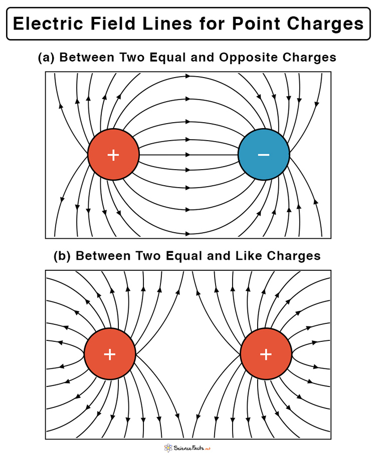 Figure 4 : How to Draw Electric Field Lines
For a Conductor
In the case of a conductor, the charges lie on the surface. The electric field vector can be resolved into perpendicular and parallel components. The parallel components cancel each other; otherwise, there will be a surface current on the conductor. The perpendicular components will add and contribute to the total electric field. Therefore, the electric field lines are drawn perpendicular to the conductor’s surface.
For a symmetrical surface like a sphere or cylinder, the perpendicular components are radial. The lines are drawn such that they radially come out (outward) of a positively charged conductor, as shown in Figure 5. If a conductor has a negative charge on its surface, then the lines will be radially inward as mentioned in the properties (#1).
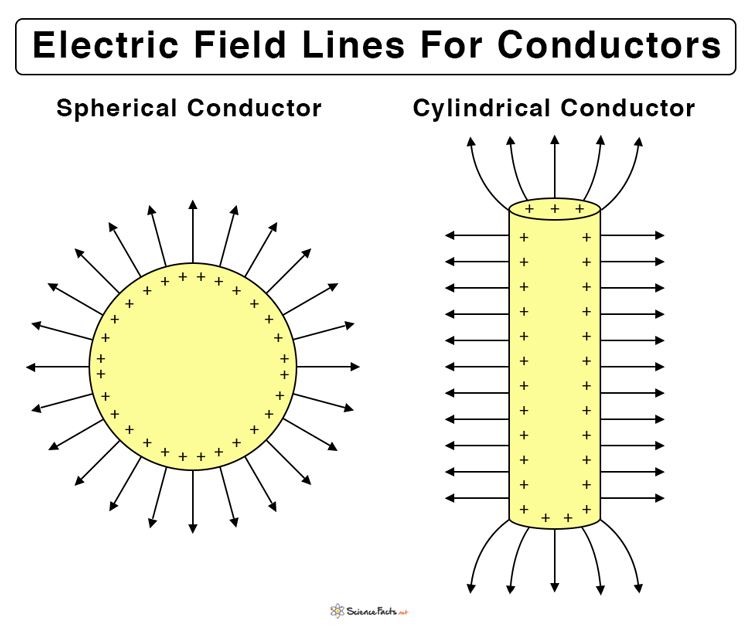 Figure 5 : Electric Field Lines Spherical Cylindrical Conductor


![Toni Kroos là ai? [ sự thật về tiểu sử đầy đủ Toni Kroos ]](https://evbn.org/wp-content/uploads/New-Project-6635-1671934592.jpg)


