
All About Electrical Sensors – Current and Voltage Sensors
Guides
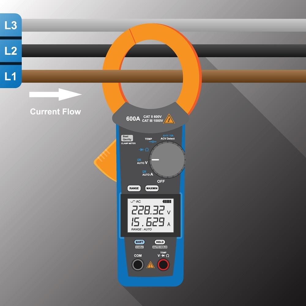
Image credit: rumruay/Shutterstock.com
Electrical Sensors/Detectors/Transducers are electronic devices that sense current, voltage, etc. and provide signals to the inputs of control devices or visual displays. Electrical sensors often rely on Hall effect detection but other methods are used as well. Key specifications include sensor type, sensor function, minimum and maximum measurement ranges, and operating temperature range. Electrical sensors are used wherever information on the state of an electrical system is needed and are employed in everything from railway systems to fan, pump, and heater monitoring. For information on other sensors please refer to our Types of Sensors article.
Mục Lục
Current Sensors
Current sensors are important control components of power electronic systems such as frequency converters, traction converters, UPS systems, and welding systems. Except in the case of resistive shunt sensing, current sensors do not have a direct electrical connection to the current being monitored and are considered non-contacting devices. They are also called current transducers. In recent years, current sensors have been engaged to monitor equipment status of pumps, compressors, heaters, conveyors, etc., replacing more conventional monitoring forms such as optical sensors and pressure and zero-speed switches. The reasoning behind this trend is the ease with which current sensors are installed and their reputation for reliability compared with electromechanical devices. They are also capable of delivering more information on the status of the device being monitored.
Hall effect current sensors measure the AC and DC amperage in conductors. The Hall effect is the basis for many kinds of sensors, including proximity and speed sensors. It is described as the voltage produced across a conductor when the conductor is in the presence of a magnetic field. In the case of a conductor, the magnetic field it produces is trapped by a ferrite ring that encircles the conductor. The ring serves to nullify any stray magnetic fields emanating from anything but the conductor itself, allowing the sensor, which is placed in a gap in the ring, to respond only to the magnetic field created by current flowing in the conductor.
Both open- and closed-loop designs are available. Open-loop designs tend to be less expensive than closed-loop designs but sacrifice something in terms of accuracy and temperature stability. This is because the open-loop sensor uses the Hall effect directly to generate an output signal. The closed-loop sensor relies on its own coil to produce a magnetic field that opposes the magnetic field generated by the current being measured. For this reason, open-loop sensors are sometimes called direct-imaging current sensors and closed-loop sensors are referred to as compensating-current sensors. In the closed-loop design, the current in the primary loop is opposed by a secondary coil wound on the same core. A feedback loop is used to balance out the flux generated by the primary loop current to eliminate the effects of temperature drift and saturation.
The range of these feedthrough sensors can be extended to sense lower currents by making multiple turns of the current-carrying conductor through the sensor aperture. Likewise, higher currents may be sensed by employing a current divider, which splits the single conductor into two smaller conductors, one of which passes through the sensor aperture.
Alternating current can also be measured inductively. The reversing magnetic field of the current-carrying conductor induces a current in the inductive sensor as the magnetic field builds and collapses. A signal conditioner then converts this to an appropriate output signal. This has become a popular method for measuring AC as it has lower power requirements than a closed-loop hall effect sensor.
Another sensor, called a Rogowski coil, provides an inexpensive method for measuring alternating current. Because they use special coreless, non-magnetic helical coils, they can measure high currents as they do not saturate. Their low inductance suits them to measuring high-speed current pulses. They are used mainly for research and development in power semiconductors, in very high voltage monitoring such as for arc furnaces, for monitoring bearing and shaft currents in large motors, in high-end welding systems, and for short-circuit testing. They are able to withstand large overloads (as in lightning strikes) and because they are immune to direct current can be used to find small AC currents in the presence of large DC currents. Rogowski coils are available in a range of sizes/lengths and are designed for installation around conductors without needing to break the conductor.
Transformer current sensors, sometimes called current clamp meters, are typically used in test equipment applications to both detect and measure high alternating currents. These devices use split iron rings that are closed around conductors. They are mainly employed for temporary current measurement. They are not used for measuring low current levels.
Sometimes, inductive current sensors are combined with self-powered switches that can provide an input to verify a given output from an automation controller. The sensor will detect the current flowing in one leg of a three-pole motor and signal the controller that a pump or fan motor has started or stopped. Such devices can be adjusted to detect current under load vs. unloaded current and thereby be used to flag broken pump couplings or failed fan belts.
Voltage sensors
Voltage sensors are used mainly by utilities to monitor the voltage in transmission lines. They are also used by utility customers to monitor voltage conditions in single- and three-phase motors to detect brownout conditions, phase loss, etc. or to protect the electronic circuits in soft starters and similar equipment from possibly damaging low voltages. Voltage sensors are also used for power factor evaluations.
Summary
This article presented a brief discussion of electrical sensors used for monitoring current and voltage. For more information on other products, consult our other guides or visit the Thomas Supplier Discovery Platform to locate potential sources of supply or view details on specific products.


![Toni Kroos là ai? [ sự thật về tiểu sử đầy đủ Toni Kroos ]](https://evbn.org/wp-content/uploads/New-Project-6635-1671934592.jpg)


