
What is the controller area network (CAN) bus?
The controller area network (CAN) bus was developed to support the networking of large numbers of electronic control units (ECUs) in automobiles. CAN is implemented using unshielded twisted pair (UTP) cabling, designed for reliability in electromagnetically noisy environments.
CAN has evolved significantly since it was first introduced in 1986, along with early ECUs. Today, there are several variations optimized for specific application scenarios. This FAQ reviews existing CAN implementations, including:
- Low-speed CAN (LS-CAN)
- High-speed CAN (HS-CAN)
- Flexible data-rate CAN (CAN FD)
- Third generation, referred to as extra-long CAN (CAN XL).
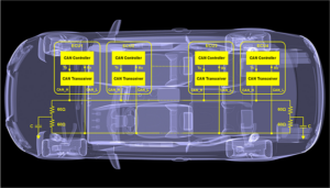
CAN is a bi-directional, multi-master, serial bus and is the most popular of the several in-vehicle network protocols currently used in automobiles. It transmits data over a UTP with a characteristic impedance of 120 Ω. One of the wires is CAN_Low (CAN_L), and the other is CAN_High (CAN_H). The ECU includes a CAN controller that interfaces with the CAN bus through a CAN transceiver, which converts logic signals into the differential voltage signals sent over the CAN bus (Figure 1).
CAN is a message-based protocol used on multiplex wiring in automobiles to save wiring harness weight and support high data rates. Each message or data frame is transmitted sequentially.
If more than one node transmits simultaneously, the data transmissions are structured to ensure that the node with the highest priority is given access to the bus. The other nodes stop all transmissions. Messages are received by all nodes, including the one that initiates the transmission. CAN is available in several variants with varying data rates and different fault-tolerance capabilities.
Low-speed fault-tolerant CAN
LS-CAN (up to 125 kbit/s) is fault-tolerant and standardized in ISO 11898-3 and ISO-11992-1. It can be implemented using a linear bus, star bus, or multiple star buses connected by a linear bus. The overall termination resistance is specified at not less than 100 Ω. LS-CAN has the termination resistor on the transceiver rather than on the cable.
The LS-CAN implementation can withstand opens, shorts, and incorrect loads on one of the data lines since it is fault-tolerant. Should a fault condition occur, the network continues to function using a single data line. Termination resistors at each node (not just at the end-point nodes) enable the preservation of network functionality. The data rate is limited to 125 kbit/s by those same fault-tolerance features.
High-speed CAN
HS-CAN is the most common CAN implementation, supporting baud rates from 40 kbit/s to 1 Mbit/s. In automotive systems, the most common rate is 500 kbit/s. Several standards govern and require the use of HS-CAN, including:
-
ISO-11898-1, -2, -5
-
ISO-11783-2
-
SAE J1939
-
SAE J2284-1, -2, -3
CANopen
-
DeviceNet
-
MilCAN
The cable length is related to the baud rate, ranging from about 40 m at 1 Mbit/s up to about 1 km at 40 kbit/s. In addition, the distance from the central CAN network that nodes can be placed (the stub length) also relates to the baud rate. CAN network stubs in automotive networks should usually be less than 1 m.
CAN FD
CAN FD is an extension of the CAN bus protocol specified in ISO 11898-1. CAN FD enables ECUs to dynamically switch to different data rates with larger or smaller message sizes.
Generally, a slower data rate can transmit more data within the same CAN frame and transport it over the CAN bus at an optimized rate. By using CAN FD, the sensor and control data can be optimized individually. It can also be sent and received by the ECU more quickly. Commands issued by the executing ECU also reach the output controller faster.
Other CAN FD features include:
-
Fewer undetected errors because of increased CRC-algorithm performance.
-
Compatibility with existing CAN 2.0 networks means that the CAN FD can be run on the same network as the classic CAN.
-
The bit rate can be up to 8MBit/s with the right CAN signal improvement capability (SIC) transceiver — moving up to eight times more data than classic CAN.
CAN data structure
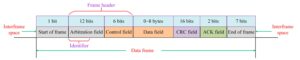
A CAN data frame consists of seven different bit fields: the beginning of the frame, an arbitration field, control field, data field, cyclic redundancy check (CRC) field, acknowledgment character (ACK) field, and the end of the frame (Figure 2).
-
The start of the frame consists of one “dominant” bit.
-
The arbitration field includes an identifier and radio-teletype receiver (RTR) bits.
-
The control field consists of six bits, including two reserved bits and four bits of data length with allowable data length values from zero to eight bytes.
-
The data field sends a buffer according to the length code, indicating the length. The same is true of the received data. Like the control field, it can be zero to eight bytes, and each byte contains eight bits.
-
The CRC code field consists of a CRC field (15 bits) and a CRC boundary character (an implicit bit). Polynomials used in CRC computation include the initial domain, arbitration domain, control domain, data domain, and the de-filling bit stream.
-
The ACK field comprises a reply gap and a reply definition recessive bits from the sender. All the nodes that receive the correct CRC sequence change the recessive bit sent into dominant bits in the reply gap of the sending node.
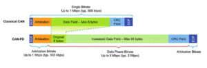
CAN FD provides a significant speed increase compared to HS-CAN. The faster speed, combined with a maximum payload size increase from (eight bytes to 64 bytes), is designed to substantially improve the net throughput of CAN FD networks (Figure 3).
CAN XL
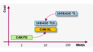
CAN XL delivers data rates up to 10Mbit/s and fills the gap between CAN FD and 100BASE-T1 (Ethernet) (Figure 4). As the third generation of the CAN data link layer, it supports all three protocol types (basic CAN, CAN FD, and CAN XL).
Similar to CAN FD, there are two bit-timing settings specified. CAN XL also provides new protocol-embedded configuration features for higher layers with optional configuration features. One example is enabling the pulse-width modulation (PWM) coding as an alternative to the normal non-return-to-zero (NRZ) coding, and switching off the error signaling. The addition of the PWM coding supports bit-rates of 10 Mbit/s or more, depending on the physical network design.
Like other CAN implementations, CAN XL is intended for backbone and sub-backbone network applications. CAN XL is also designed for easy integration into TCP/IP network systems.
Designers interested in deploying CAN XL should be aware of the activities of the special interest group (SIG) at CAN in Automation (CiA), the international users’ and manufacturers’ group for CAN.
The CiA SIG has developed several documents that include CAN XL-related specifications and recommendations:
-
CiA 610: CAN XL specification and test plans
-
CiA 611: CAN XL higher-layer services
-
CiA 612: CAN XL guidelines and application notes
-
CiA 613: CAN XL add-on services
Summary
CAN is currently the most widely-used in-vehicle networking protocol. It’s a bi-directional, multi-master, serial bus that uses UTP cabling to ensure reliability in electromagnetically noisy environments.
CAN is available in several performance versions, including LS-CAN, HS-CAN, and CAN-XL. It suits the needs of various applications, including those that rely on a highly robust operation and extended data sets. The latest generation, CAN XL, targets applications that currently use the 10BASE-T1 Ethernet and deliver data rates up to 10Mbit/s, filling the gap between CAN FD and 100BASE-T1 Ethernet.
References


![Toni Kroos là ai? [ sự thật về tiểu sử đầy đủ Toni Kroos ]](https://evbn.org/wp-content/uploads/New-Project-6635-1671934592.jpg)


