STP Topology Change Notification (TCN)
How does spanning-tree deal with topology changes? This is a topic that isn’t (heavily) tested on the CCNP SWITCH exam but it’s very important to understand if you deal with a network with a lot of switches.
Let me show you an example so I can explain a couple of things:
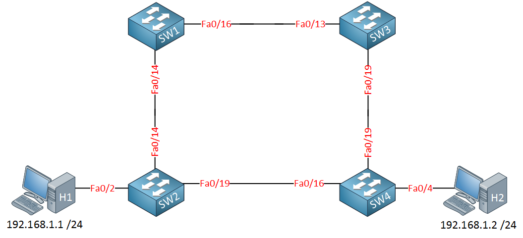
Let’s take a look at the picture above. We have two computers because I need something to fill the MAC address tables of these switches. All switches have the default configuration.
SW3(config)#spanning-tree vlan 1 priority 4096SW2(config)#interface fa0/19
SW2(config-if)#spanning-tree cost 50I want SW3 to be the root bridge and the fa0/19 interface of SW2 should be blocked. I’ll show you why in a minute. Let’s see what the state is of all these interfaces:
SW1#show spanning-tree | begin Interface
Interface           Role Sts Cost      Prio.Nbr Type
------------------- ---- --- --------- -------- --------------------------------
Fa0/14              Desg FWD 19        128.16   P2p
Fa0/16 Root FWD 19 128.18 P2pSW2#show spanning-tree | begin Interface
Interface Role Sts Cost Prio.Nbr Type
------------------- ---- --- --------- -------- --------------------------------
Fa0/2 Desg FWD 19 128.4 P2p
Fa0/14 Root FWD 19 128.16 P2p
Fa0/19 Altn BLK 50 128.21 P2pSW3#show spanning-tree | begin Interface
Interface Role Sts Cost Prio.Nbr Type
---------------- ---- --- --------- -------- --------------------------------
Fa0/13 Desg FWD 19 128.13 P2p
Fa0/19 Desg FWD 19 128.19 P2pSW4#show spanning-tree | begin Interface
Interface Role Sts Cost Prio.Nbr Type
------------------- ---- --- --------- -------- --------------------------------
Fa0/4 Desg FWD 19 128.4 P2p
Fa0/16 Desg FWD 19 128.16 P2p
Fa0/19 Root FWD 19 128.19 P2pSo here we have all the different interfaces, time to draw a nice picture!
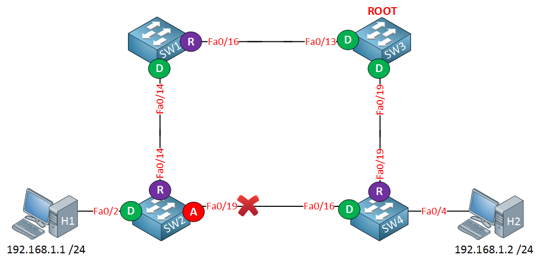
Traffic between H1 and H2 will flow from SW2 to SW1, SW3 and then towards SW4. Interface fa0/19 on SW2 has been blocked.
Let’s generate some traffic so the switches learn the MAC addresses of the computers:
C:Documents and SettingsH1>ping 192.168.1.2

Pinging 192.168.1.2 with 32 bytes of data:

Reply from 192.168.1.2: bytes=32 time<1ms TTL=128
Reply from 192.168.1.2: bytes=32 time<1ms TTL=128
Reply from 192.168.1.2: bytes=32 time<1ms TTL=128
Reply from 192.168.1.2: bytes=32 time<1ms TTL=128

Ping statistics for 192.168.1.2:
    Packets: Sent = 4, Received = 4, Lost = 0 (0% loss),
Approximate round trip times in milli-seconds:
    Minimum = 0ms, Maximum = 0ms, Average = 0ms
A simple ping will generate some frames and the switches will learn the MAC addresses.
In my case these are the MAC addresses for the computers:
- H1: 000c.2928.5c6c
- H2: 000c.29e2.03ba
SW1#show mac address-table dynamic
          Mac Address Table
-------------------------------------------

Vlan    Mac Address       Type        Ports
----    -----------       --------    -----
   1    000c.2928.5c6c    DYNAMIC     Fa0/14
1 000c.29e2.03ba DYNAMIC Fa0/16SW2#show mac address-table dynamic
Mac Address Table
-------------------------------------------
Vlan Mac Address Type Ports
---- ----------- -------- -----
1 000c.2928.5c6c DYNAMIC Fa0/2
1 000c.29e2.03ba DYNAMIC Fa0/14SW3#show mac address-table dynamic
Mac Address Table
-------------------------------------------
Vlan Mac Address Type Ports
---- ----------- -------- -----
1 000c.2928.5c6c DYNAMIC Fa0/13
1 000c.29e2.03ba DYNAMIC Fa0/19SW4#show mac address-table dynamic
Mac Address Table
-------------------------------------------
Vlan Mac Address Type Ports
---- ----------- -------- -----
1 000c.2928.5c6c DYNAMIC Fa0/19
1 000c.29e2.03ba DYNAMIC Fa0/4
We can confirm the traffic path by looking at the MAC address table. I like to use the show mac address-table dynamic command so we don’t have to browse through a list of static MAC addresses.
Do you have any idea how long a switch will store a MAC address?
SW1#show mac address-table aging-time
Global Aging Time:  300
If we look at one of the switches we can check the default aging time of the MAC address table. As you can see this is 300 seconds (5 minutes by default). If a host has been silent for 5 minutes its MAC address will be removed from the table.
Why do we care about aging time? I’ll show you why!
C:Documents and SettingsH1>ping 192.168.1.2 -tFirst I’m going to get some traffic going from H1 to H2. By using ping –t it will run forever.
The next step will be to unplug one of the cables:
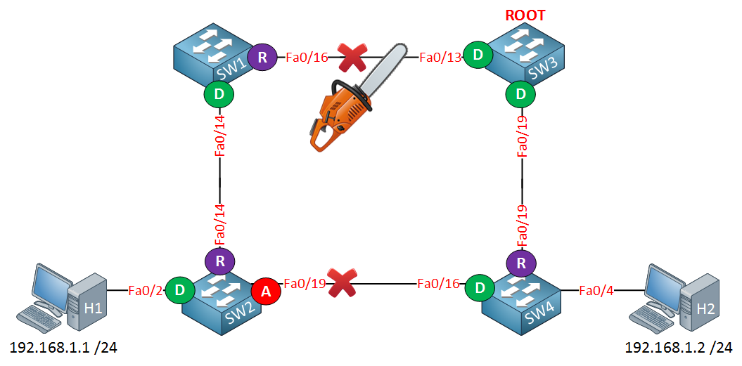
Assume the link between SW1 and SW3 fails. H1 and H2 will be unable to communicate with each other until the fa0/19 interface of SW2 goes into forwarding.
It will take a maximum of 50 seconds for SW2 to move the fa0/19 interface from blocking to listening, learning and finally the forwarding state.
Meanwhile SW2 still has the MAC address of H2 in its MAC address table and will keep forwarding it to SW1 where it will be dropped. It will be impossible for our computers to communicate with each other for 300 seconds until the MAC address tables age out.
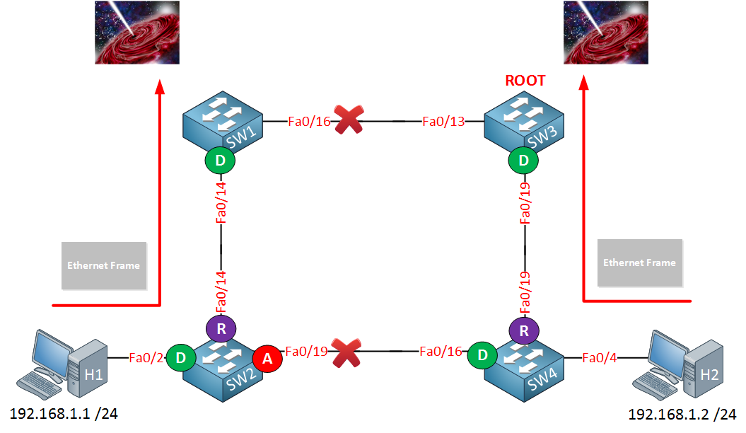
“Sending Ethernet frames to a place where no frame has gone before doesn’t sound like a good idea if you want to keep your users happy…”
The idea of MAC address tables that age out after 300 seconds works perfectly fine in a stable network but not when the topology changes. Of course there’s a solution to every problem and that’s why spanning-tree has a topology change mechanism.
When a switch detects a change in the network (interface going down or into forwarding state) it will advertise this event to the whole switched network.
When the switches receive this message they will reduce the aging time of the MAC address table from 300 seconds to 15 seconds (this is the forward delay timer). This message is called the TCN (Topology Change Notification).
To take a closer look at the TCN we’ll have to do some debugging…
SW1#debug spanning-tree events
Spanning Tree event debugging is onSW2#debug spanning-tree events
Spanning Tree event debugging is onSW3#debug spanning-tree events
Spanning Tree event debugging is onSW4#debug spanning-tree events
Spanning Tree event debugging is onI’m going to enable debug spanning-tree events on all switches so you can see this process in action.
Now we will shut the Interface fa0/16 on SW1 to simulate a link failure:
SW1(config)#interface fa0/16
SW1(config-if)#shutdown
Here’s what you’ll see:
SW1#STP: VLAN0001 sent Topology Change Notice on Fa0/14
You will see quite some debug information but somewhere along the lines you’ll see that SW1 is generating a topology change notification and sends it on its fa0/14 interface to SW2. Here’s what you see on SW2:
SW2#STP: VLAN0001 Topology Change rcvd on Fa0/14
SW2 will throw quite some debug stuff in your face but this is what I was looking for. You can see that it received the topology change notification from SW1. Upon arrival of this topology change notification SW2 will age out its MAC address table in 15 seconds.
What will SW2 do with this information? Look below:
SW2#STP: VLAN0001 new root port Fa0/19, cost 69
SW2#STP: VLAN0001 Fa0/19 -> listening
SW2#STP: VLAN0001 Topology Change rcvd on Fa0/14
SW2#STP: VLAN0001 sent Topology Change Notice on Fa0/19
SW2#STP: VLAN0001 Fa0/19 -> learning
SW2#STP: VLAN0001 sent Topology Change Notice on Fa0/19
SW2#STP: VLAN0001 Fa0/19 -> forwarding
SW2 decides that fa0/19 is now the new root port and you can see the transition from listening to learning and forwarding mode. It’s also sending a topology change notification towards SW4.
SW3#STP: VLAN0001 Topology Change rcvd on Fa0/19
SW3 receives a topology change notification on its fa0/19 interface and will reduce its age out timer of the MAC address table to 15 seconds.
SW4#STP: VLAN0001 Topology Change rcvd on Fa0/16
SW4#STP: VLAN0001 sent Topology Change Notice on Fa0/19
Here we see that SW4 receives the topology change notification from SW2 and as a result it will reduce its age out timer of the MAC address table to 15 seconds. It’s also sending a topology change notification to SW3.
All switches received the topology change notification and set their age out timer to 15 seconds. SW2 doesn’t receive any Ethernet Frames with the MAC address of H2 as the source on its fa0/14 interface and will remove this entry from the MAC address table.
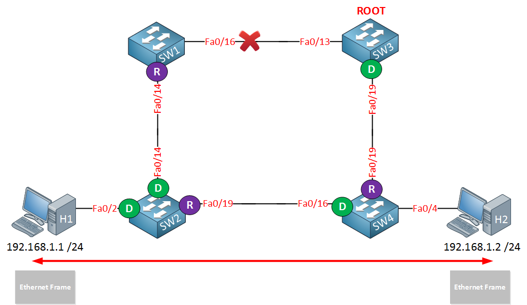
Meanwhile the fa0/19 interface on SW2 changed from blocking to listening, learning and forwarding state (50 seconds total). SW2 will now learn the MAC address of H2 on its fa0/19 interface and life is good!
Of course the same thing will happen for the MAC address of H1 on SW4.
Are you following me so far? To keep a long story short…we need the topology change notification to reduce the MAC address table aging timer from 300 seconds to 15 seconds to prevent blackholing traffic in a situation like I just explained to you.
So which switches will send and forward the topology change notifications? In our previous debug you saw a couple of messages but where do we send them and why? Is it flooded to all switches? Let’s check it out!
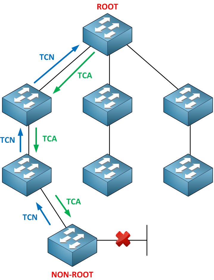
In a normal situation a non-root switch will receive BPDUs on its root port but will never send any BPDUs to the root bridge. When a non-root switch detects a topology change it will generate a topology change notification and send it on its root port towards the root bridge.
When a switch receives the topology change notification it will send a (TCA) topology change acknowledgement on its designated port towards the downstream switch. It will create a topology change notification itself and send it on its root port as well…we will work our way up the tree until we reach the root bridge.
What kind of message is used for the TCN? Take a look at this BPDU:


You can see it has a field called BPDU type. This value will change to indicate it’s a topology change notification.
Once the topology change notification reaches the root bridge it will set the TC (topology change) bit in the BPDUs it will send.
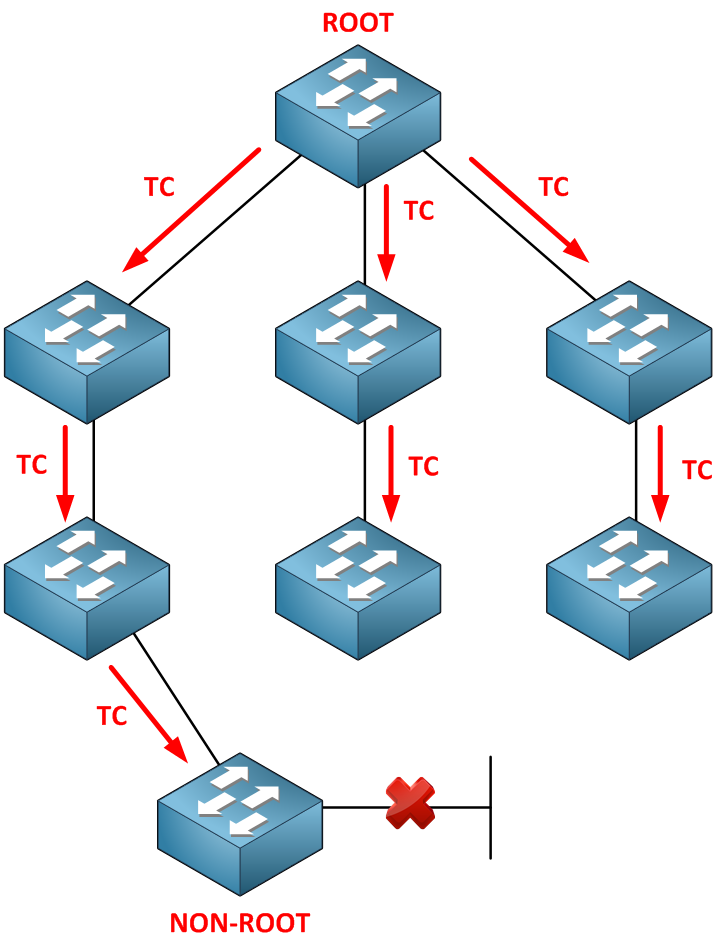
These BPDUs will be forwarded to all the other switches in our network so they can reduce their aging time of the MAC address table. Switches will receives these messages on both forwarding and blocked ports.
The root bridge will send BPDUs and it will set the flag field to represent the topology change.


![Toni Kroos là ai? [ sự thật về tiểu sử đầy đủ Toni Kroos ]](https://evbn.org/wp-content/uploads/New-Project-6635-1671934592.jpg)


