Making A Low-Cost Stereo Camera Using OpenCV | LearnOpenCV #
In this post, we will learn how to create a custom low-cost stereo camera (using a pair of webcams ) and capture 3D videos with it using OpenCV. We provide code in Python and C++.
Example of a 3D video. (Source link)
We all have enjoyed 3D movies and videos like the one shown above. You need Red-Cyan color 3D glasses, like the one in figure 1, to experience the 3D effect. How does it work? How can we experience the 3D effect when the screen is just flat plane? These are captured using a stereo camera setup.
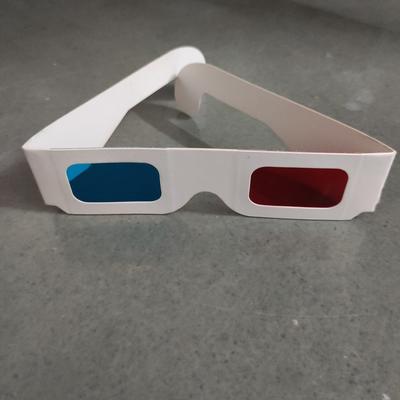 Figure 1 – red-cyan 3D glasses
In the previous post we learnt about stereo cameras and how they are used to help a computer perceive depth. In this post we learn to create our own stereo camera and understand how it can be used to create 3D videos. Specifically, you will learn the following:
Mục Lục
Steps To Create The Stereo Camera Setup
A stereo camera setup usually contains two identical cameras placed a fixed distance apart. Industry grade standard stereo camera setups use an identical pair of cameras.
To create one at home, we need the following:
- Two USB webcams (Preferably the same model).
- Rigid base to fix the cameras (wood, cardboard, PVC foam board).
- Clamps or Duct tape.
One can be creative in using different components to create the stereo camera, but the essential requirement is to keep the cameras rigidly fixed and parallel.
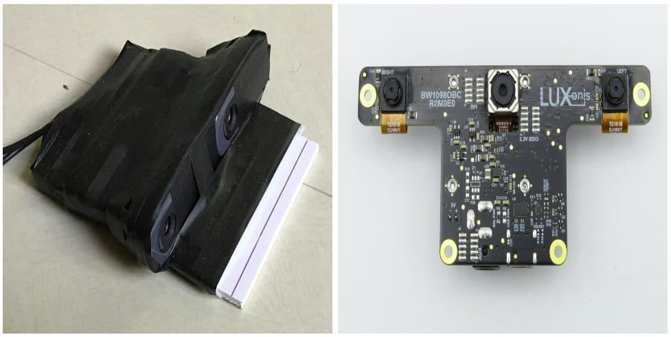 Figure 2 – Image of my DIY stereo camera (Left) and the OpenCV AI Kit With Depth (OAK-D) (Right). The two cameras on the sides of OAKD form the stereo camera setup. Source for image of OAK-D.
Many people have created and shared their DIY stereo camera setups like mine shown in the left image of figure 2 or the one shared in this post.
Once we fix the cameras and ensure that they are correctly aligned, are we done? Are we ready to generate disparity maps and 3D videos?
Master Generative AI for CV
Get expert guidance, insider tips & tricks. Create stunning images, learn to fine tune diffusion models, advanced Image editing techniques like In-Painting, Instruct Pix2Pix and many more
Importance of Stereo Calibration and Rectification
To understand the importance of stereo calibration and stereo rectification, we try to generate a disparity map using the images captured from our stereo setup without any calibration or stereo rectification.
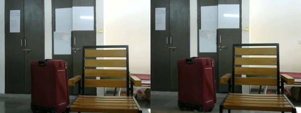 Figure 3 – Left and Right images captured from the stereo camera setup
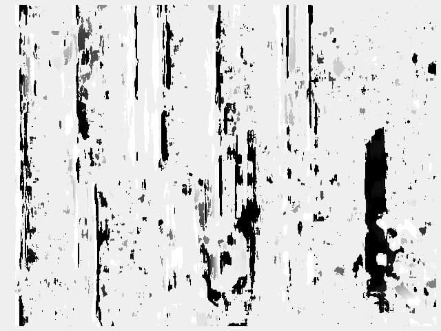 Figure 4 – Disparity map generated using the right and left images without stereo calibration
We observe that the disparity map generated with an Uncalibrated stereo camera setup is very noisy and inaccurate. Why does this happen?
Based on the previous post , the corresponding key points should have equal Y coordinates to simplify the point correspondence search. In Figure 5, when we plot the matching lines between a few corresponding points, we observe that the lines are not completely horizontal.
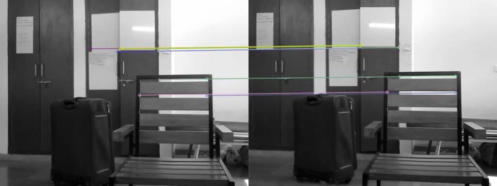 Figure 5 – Plotting matches between corresponding points.
It is also observed that the Y coordinates of corresponding points are not equal. Figure 6 shows a pair of stereo images with point correspondence, and the disparity map generated using these images. We observe that now the disparity map is less noisy compared to the previous one. In this case, the corresponding key points have equal Y coordinates. Such a case is only possible when the cameras are parallel. This is a special case of two-view geometry where the images are parallel and related by just a horizontal translation. This is essential because the method used to generate the disparity map searches only horizontally for point correspondence.
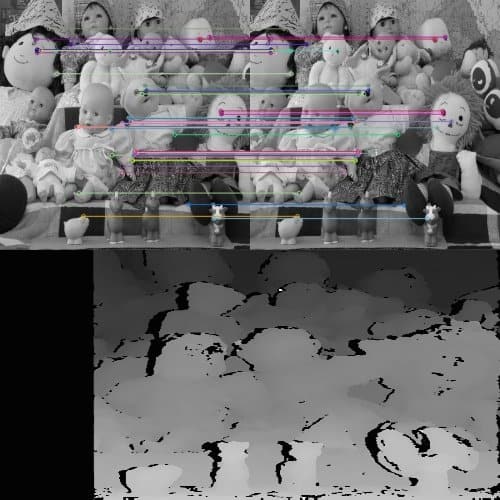 Figure 6 – Feature matches for a stereo image pair and generated disparity map.
Awesome! All we need to do is align our cameras and make them completely parallel. So do we adjust the cameras manually based on trial and error? Well, as a fun activity, you can give it a try! Spoiler alert!! It will take a long time to adjust the cameras manually to get a clear disparity map. Moreover, every time the setup is disturbed and the cameras are displaced, we have to repeat this process. This is time-consuming and not an ideal solution.
Instead of physically adjusting the cameras, we do this on the software side. We use a method called Stereo Image Rectification.[1] Figure 7 explains the process of stereo rectification. The idea is to re-project the two images on a common plane parallel to the line passing through the optical centers. This ensures that the corresponding points have the same Y coordinate and are related simply by a horizontal translation.
Figure 7 – Process of stereo rectification. (source link)
Steps For Stereo Calibration and Rectification
Based on our previous post on lens distortion, we know that images captured by a camera suffer from lens distortion. Hence Apart from stereo rectification, it is also essential to undistort the images. So the overall process is as follows:
- Calibrate individual cameras using the standard OpenCV calibration method explained in the camera calibration post.
- Determine the transformation between the two cameras used in the stereo camera setup.
- Using the parameters obtained in the previous steps and the stereoCalibrate method, we determine the transformations applied to both the images for stereo rectification.
- Finally, a mapping required to find the undistorted and rectified stereo image pair is obtained using the initUndistortRectifyMap method.
- This mapping is applied to the original images to get a rectified undistorted stereo image pair.
To perform these steps, we capture images of a calibration pattern. The following video shows different images captured to calibrate the DIY stereo camera.
Let us understand the code for calibration and rectification.
Step 1: Individual calibration of the right and left cameras of the stereo setup
Video showing the process of capturing images for stereo calibration
We perform individual calibration of both the cameras before performing stereo calibration. But, why do we need to calibrate the cameras individually if the stereoCalibrate() method can also perform calibration of each of the two cameras?
As there are many parameters to calculate (large parameter space) and there is accumulation of errors in steps like corner detection and approximating points to integers. This increases the chances of the iterative method to diverge from the correct solution. Hence we calculate the camera parameters individually and use the stereoCalibrate() method only to find the transformation between the stereo camera pair, the Essential matrix and the Fundamental matrix.
But how will the algorithm know that the calibration of individual cameras is to be skipped? For this we set the flag CALIB_FIX_INTRINSIC and pass it to the method.
Download Code
To easily follow along this tutorial, please download code by clicking on the button below. It’s FREE!
To easily follow along this tutorial, please download code by clicking on the button below. It’s FREE!
C++
// Defining the dimensions of checkerboard
int CHECKERBOARD[2]{6,9};

// Creating vector to store vectors of 3D points for each checkerboard image
std::vector<std::vector<cv::Point3f> > objpoints;

// Creating vector to store vectors of 2D points for each checkerboard image
std::vector<std::vector<cv::Point2f> > imgpointsL, imgpointsR;

// Defining the world coordinates for 3D points
std::vector<cv::Point3f> objp;
for(int i{0}; i<CHECKERBOARD[1]; i++)
{
  for(int j{0}; j<CHECKERBOARD[0]; j++)
    objp.push_back(cv::Point3f(j,i,0));
}

// Extracting path of individual image stored in a given directory
std::vector<cv::String> imagesL, imagesR;
// Path of the folder containing checkerboard images
std::string pathL = "./data/stereoL/*.png";
std::string pathR = "./data/stereoR/*.png";

cv::glob(pathL, imagesL);
cv::glob(pathR, imagesR);

cv::Mat frameL, frameR, grayL, grayR;
// vector to store the pixel coordinates of detected checker board corners
std::vector<cv::Point2f> corner_ptsL, corner_ptsR;
bool successL, successR;

// Looping over all the images in the directory
for(int i{0}; i<imagesL.size(); i++)
{
  frameL = cv::imread(imagesL[i]);
  cv::cvtColor(frameL,grayL,cv::COLOR_BGR2GRAY);

  frameR = cv::imread(imagesR[i]);
  cv::cvtColor(frameR,grayR,cv::COLOR_BGR2GRAY);

  // Finding checker board corners
  // If desired number of corners are found in the image then success = true
  successL = cv::findChessboardCorners(
    grayL,
    cv::Size(CHECKERBOARD[0],CHECKERBOARD[1]),
    corner_ptsL);
    // cv::CALIB_CB_ADAPTIVE_THRESH | cv::CALIB_CB_FAST_CHECK | cv::CALIB_CB_NORMALIZE_IMAGE);

  successR = cv::findChessboardCorners(
    grayR,
    cv::Size(CHECKERBOARD[0],CHECKERBOARD[1]),
    corner_ptsR);
    // cv::CALIB_CB_ADAPTIVE_THRESH | cv::CALIB_CB_FAST_CHECK | cv::CALIB_CB_NORMALIZE_IMAGE);
  /*
    * If desired number of corner are detected,
    * we refine the pixel coordinates and display
    * them on the images of checker board
  */
  if((successL) && (successR))
  {
    cv::TermCriteria criteria(cv::TermCriteria::EPS | cv::TermCriteria::MAX_ITER, 30, 0.001);

    // refining pixel coordinates for given 2d points.
    cv::cornerSubPix(grayL,corner_ptsL,cv::Size(11,11), cv::Size(-1,-1),criteria);
    cv::cornerSubPix(grayR,corner_ptsR,cv::Size(11,11), cv::Size(-1,-1),criteria);

    // Displaying the detected corner points on the checker board
    cv::drawChessboardCorners(frameL, cv::Size(CHECKERBOARD[0],CHECKERBOARD[1]), corner_ptsL,successL);
    cv::drawChessboardCorners(frameR, cv::Size(CHECKERBOARD[0],CHECKERBOARD[1]), corner_ptsR,successR);

    objpoints.push_back(objp);
    imgpointsL.push_back(corner_ptsL);
    imgpointsR.push_back(corner_ptsR);
  }

  cv::imshow("ImageL",frameL);
  cv::imshow("ImageR",frameR);
  cv::waitKey(0);
}

cv::destroyAllWindows();

cv::Mat mtxL,distL,R_L,T_L;
cv::Mat mtxR,distR,R_R,T_R;
cv::Mat Rot, Trns, Emat, Fmat;
cv::Mat new_mtxL, new_mtxR;

// Calibrating left camera
cv::calibrateCamera(objpoints,
                    imgpointsL,
                    grayL.size(),
                    mtxL,
                    distL,
                    R_L,
                    T_L);

new_mtxL = cv::getOptimalNewCameraMatrix(mtxL,
                              distL,
                              grayL.size(),
                              1,
                              grayL.size(),
                              0);

// Calibrating right camera
cv::calibrateCamera(objpoints,
                    imgpointsR,
                    grayR.size(),
                    mtxR,
                    distR,
                    R_R,
                    T_R);

new_mtxR = cv::getOptimalNewCameraMatrix(mtxR,
                              distR,
                              grayR.size(),
                              1,
                              grayR.size(),
                              0);
Python
# Set the path to the images captured by the left and right cameras
pathL = "./data/stereoL/"
pathR = "./data/stereoR/"

# Termination criteria for refining the detected corners
criteria = (cv2.TERM_CRITERIA_EPS + cv2.TERM_CRITERIA_MAX_ITER, 30, 0.001)


objp = np.zeros((9*6,3), np.float32)
objp[:,:2] = np.mgrid[0:9,0:6].T.reshape(-1,2)

img_ptsL = []
img_ptsR = []
obj_pts = []

for i in tqdm(range(1,12)):
	imgL = cv2.imread(pathL+"img%d.png"%i)
	imgR = cv2.imread(pathR+"img%d.png"%i)
	imgL_gray = cv2.imread(pathL+"img%d.png"%i,0)
	imgR_gray = cv2.imread(pathR+"img%d.png"%i,0)

	outputL = imgL.copy()
	outputR = imgR.copy()

	retR, cornersR =  cv2.findChessboardCorners(outputR,(9,6),None)
	retL, cornersL = cv2.findChessboardCorners(outputL,(9,6),None)

	if retR and retL:
		obj_pts.append(objp)
		cv2.cornerSubPix(imgR_gray,cornersR,(11,11),(-1,-1),criteria)
		cv2.cornerSubPix(imgL_gray,cornersL,(11,11),(-1,-1),criteria)
		cv2.drawChessboardCorners(outputR,(9,6),cornersR,retR)
		cv2.drawChessboardCorners(outputL,(9,6),cornersL,retL)
		cv2.imshow('cornersR',outputR)
		cv2.imshow('cornersL',outputL)
		cv2.waitKey(0)

		img_ptsL.append(cornersL)
		img_ptsR.append(cornersR)


# Calibrating left camera
retL, mtxL, distL, rvecsL, tvecsL = cv2.calibrateCamera(obj_pts,img_ptsL,imgL_gray.shape[::-1],None,None)
hL,wL= imgL_gray.shape[:2]
new_mtxL, roiL= cv2.getOptimalNewCameraMatrix(mtxL,distL,(wL,hL),1,(wL,hL))

# Calibrating right camera
retR, mtxR, distR, rvecsR, tvecsR = cv2.calibrateCamera(obj_pts,img_ptsR,imgR_gray.shape[::-1],None,None)
hR,wR= imgR_gray.shape[:2]
new_mtxR, roiR= cv2.getOptimalNewCameraMatrix(mtxR,distR,(wR,hR),1,(wR,hR))
Step 2: Performing stereo calibration with fixed intrinsic parameters
As the cameras are calibrated, we pass them to the stereoCalibrate() method and set the CALIB_FIX_INTRINSIC flag. We also pass the 3D points and corresponding 2D pixel coordinates captured in both images.
The method computes the rotation and translation between the two cameras and the Essential and Fundamental matrix.
C++
cv::Mat Rot, Trns, Emat, Fmat;
int flag = 0;
flag |= cv::CALIB_FIX_INTRINSIC;

// This step is performed to transformation between the two cameras and calculate Essential and
// Fundamenatl matrix
cv::stereoCalibrate(objpoints,
                    imgpointsL,
                    imgpointsR,
                    new_mtxL,
                    distL,
                    new_mtxR,
                    distR,
                    grayR.size(),
                    Rot,
                    Trns,
                    Emat,
                    Fmat,
                    flag,
                    cv::TermCriteria(cv::TermCriteria::MAX_ITER + cv::TermCriteria::EPS, 30, 1e-6));
Python
flags = 0
flags |= cv2.CALIB_FIX_INTRINSIC
# Here we fix the intrinsic camara matrixes so that only Rot, Trns, Emat and Fmat are calculated.
# Hence intrinsic parameters are the same

criteria_stereo= (cv2.TERM_CRITERIA_EPS + cv2.TERM_CRITERIA_MAX_ITER, 30, 0.001)


# This step is performed to transformation between the two cameras and calculate Essential and Fundamenatl matrix
retS, new_mtxL, distL, new_mtxR, distR, Rot, Trns, Emat, Fmat = cv2.stereoCalibrate(obj_pts, img_ptsL, img_ptsR, new_mtxL, distL, new_mtxR, distR, imgL_gray.shape[::-1], criteria_stereo, flags)
Step 3: Stereo Rectification
Using the camera intrinsics and the rotation and translation between the cameras, we can now apply stereo rectification. Stereo rectification applies rotations to make both camera image planes be in the same plane. Along with the rotation matrices, the stereoRectify method also returns the projection matrices in the new coordinate space.
C++
cv::Mat rect_l, rect_r, proj_mat_l, proj_mat_r, Q;

// Once we know the transformation between the two cameras we can perform
// stereo rectification
cv::stereoRectify(new_mtxL,
                  distL,
                  new_mtxR,
                  distR,
                  grayR.size(),
                  Rot,
                  Trns,
                  rect_l,
                  rect_r,
                  proj_mat_l,
                  proj_mat_r,
                  Q,
                  1);
Python
rectify_scale= 1
rect_l, rect_r, proj_mat_l, proj_mat_r, Q, roiL, roiR= cv2.stereoRectify(new_mtxL, distL, new_mtxR, distR, imgL_gray.shape[::-1], Rot, Trns, rectify_scale,(0,0))
Step 4: Compute the mapping required to obtain the undistorted rectified stereo image pair
As we assume that the cameras are rigidly fixed, the transformations need not be calculated again. Hence we calculate the mappings that transform a stereo image pair to an undistorted rectified stereo image pair and store them for further use.
C++
cv::Mat Left_Stereo_Map1, Left_Stereo_Map2;
cv::Mat Right_Stereo_Map1, Right_Stereo_Map2;

cv::initUndistortRectifyMap(new_mtxL,
                            distL,
                            rect_l,
                            proj_mat_l,
                            grayR.size(),
                            CV_16SC2,
                            Left_Stereo_Map1,
                            Left_Stereo_Map2);

cv::initUndistortRectifyMap(new_mtxR,
                            distR,
                            rect_r,
                            proj_mat_r,
                            grayR.size(),
                            CV_16SC2,
                            Right_Stereo_Map1,
                            Right_Stereo_Map2);

cv::FileStorage cv_file = cv::FileStorage("improved_params2_cpp.xml", cv::FileStorage::WRITE);
cv_file.write("Left_Stereo_Map_x",Left_Stereo_Map1);
cv_file.write("Left_Stereo_Map_y",Left_Stereo_Map2);
cv_file.write("Right_Stereo_Map_x",Right_Stereo_Map1);
cv_file.write("Right_Stereo_Map_y",Right_Stereo_Map2);
Python
Left_Stereo_Map= cv2.initUndistortRectifyMap(new_mtxL, distL, rect_l, proj_mat_l,
                                             imgL_gray.shape[::-1], cv2.CV_16SC2)
Right_Stereo_Map= cv2.initUndistortRectifyMap(new_mtxR, distR, rect_r, proj_mat_r,
                                              imgR_gray.shape[::-1], cv2.CV_16SC2)

print("Saving paraeters ......")
cv_file = cv2.FileStorage("improved_params2.xml", cv2.FILE_STORAGE_WRITE)
cv_file.write("Left_Stereo_Map_x",Left_Stereo_Map[0])
cv_file.write("Left_Stereo_Map_y",Left_Stereo_Map[1])
cv_file.write("Right_Stereo_Map_x",Right_Stereo_Map[0])
cv_file.write("Right_Stereo_Map_y",Right_Stereo_Map[1])
cv_file.release()
How Do 3D Glasses Work?
Once our DIY stereo camera is calibrated, we are ready to create 3D videos. But before we understand how to make 3D videos, it is essential to understand how the 3D glasses work.
We perceive the world using a binocular vision system. Our eyes are in laterally varying positions. Hence they capture somewhat different information.
What is the difference between the information captured by our left and right eye?
Let’s do a simple experiment! Stretch your arm in front and hold any object in your hand. Now, look at the object with one eye closed. After a second, repeat this with the other eye and keep alternating. Do you observe any difference in what both your eyes can see?
The differences are mainly in the relative horizontal position of objects. These positional differences are referred to as horizontal disparities. In the previous post, we had calculated a disparity map using a pair of stereo images.
Now, bring the object closer to you and repeat the same experiment. What changes did you observe now? The horizontal disparities corresponding to the object increase. Hence, the higher the disparities for an object, the closer it is. This is how we use stereopsis to perceive depth using our binocular vision system.
We can simulate such disparities by artificially presenting two different images separately to each eye using a method called stereoscopy. Initially, for 3D movies, people achieved by encoding each eye’s image using filters of red and cyan colors. They used the red-cyan 3D glasses to ensure that each of the two images reached the intended eye. This created the illusion of depth. The stereoscopic effect generated with this method is called anaglyph 3D. Hence, the images are called anaglyph images, and the glasses are called anaglyph 3D glasses.
Master Generative AI for CV
Get expert guidance, insider tips & tricks. Create stunning images, learn to fine tune diffusion models, advanced Image editing techniques like In-Painting, Instruct Pix2Pix and many more
Creating a custom 3D video
We understood how a stereo image pair is converted to its anaglyph image to create an illusion of depth when viewed using the anaglyph glasses. But how do we capture these stereo images? Yup! this is where we use our DIY stereo camera. We capture the stereo images using our DIY stereo camera setup and create an anaglyph image for each stereo image pair. We then save all the consecutive anaglyph images as a video. That is how we make a 3D video!
Let’s dive into the code and create our 3D video.
C++
cv::imshow("Left image before rectification",frameL);
cv::imshow("Right image before rectification",frameR);

cv::Mat Left_nice, Right_nice;

// Apply the calculated maps for rectification and undistortion
cv::remap(frameL,
          Left_nice,
          Left_Stereo_Map1,
          Left_Stereo_Map2,
          cv::INTER_LANCZOS4,
          cv::BORDER_CONSTANT,
          0);

cv::remap(frameR,
          Right_nice,
          Right_Stereo_Map1,
          Right_Stereo_Map2,
          cv::INTER_LANCZOS4,
          cv::BORDER_CONSTANT,
          0);


cv::imshow("Left image after rectification",Left_nice);
cv::imshow("Right image after rectification",Right_nice);

cv::waitKey(0);

cv::Mat Left_nice_split[3], Right_nice_split[3];

std::vector<cv::Mat> Anaglyph_channels;

cv::split(Left_nice, Left_nice_split);
cv::split(Right_nice, Right_nice_split);

Anaglyph_channels.push_back(Right_nice_split[0]);
Anaglyph_channels.push_back(Right_nice_split[1]);
Anaglyph_channels.push_back(Left_nice_split[2]);

cv::Mat Anaglyph_img;

cv::merge(Anaglyph_channels, Anaglyph_img);

cv::imshow("Anaglyph image", Anaglyph_img);
cv::waitKey(0);
Python
cv2.imshow("Left image before rectification", imgL)
cv2.imshow("Right image before rectification", imgR)

Left_nice= cv2.remap(imgL,Left_Stereo_Map[0],Left_Stereo_Map[1], cv2.INTER_LANCZOS4, cv2.BORDER_CONSTANT, 0)
Right_nice= cv2.remap(imgR,Right_Stereo_Map[0],Right_Stereo_Map[1], cv2.INTER_LANCZOS4, cv2.BORDER_CONSTANT, 0)

cv2.imshow("Left image after rectification", Left_nice)
cv2.imshow("Right image after rectification", Right_nice)
cv2.waitKey(0)

out = Right_nice.copy()
out[:,:,0] = Right_nice[:,:,0]
out[:,:,1] = Right_nice[:,:,1]
out[:,:,2] = Left_nice[:,:,2]

cv2.imshow("Output image", out)
cv2.waitKey(0)
3D video created using the custom built stereo camera setup and the code explained above
The first post of the Introduction to Spatial AI discussed all the fundamental concepts related to two-view geometry and stereo vision. This post was about creating a low-cost stereo camera setup, calibrating it, and using it to create custom 3D movies.
The next post of this series will discuss another exciting application and explain some more fundamental concepts about stereo vision.
References
[1] C. Loop and Z. Zhang. Computing Rectifying Homographies for Stereo Vision. IEEE Conf. Computer Vision and Pattern Recognition, 1999.


![Toni Kroos là ai? [ sự thật về tiểu sử đầy đủ Toni Kroos ]](https://evbn.org/wp-content/uploads/New-Project-6635-1671934592.jpg)


