Electric Transformers: Types, Applications, Benefits, and Components
Mục Lục
Electric Transformers
Contact Companies
Please fill out the following form to submit a Request for Quote to any of the following companies listed on
Get Your Company Listed on this Power Page
Introduction
This article will take an in-depth look at electric transformers.
The article will bring more detail on topics such as:
- Principle of Electric Transformers
- Types of Electric Transformers
- Applications and Benefits of Electric Transformers
- And Much More…

Chapter 1: Principle of Electric Transformers
This chapter will discuss what electric transformers are, how they are made, and how they function.
What are Electric Transformers?
Electric transformers are static electrical machines that transform electric power from one circuit to the other without changing the frequency. An electrical transformer can increase or decrease the voltage with a corresponding increase or decrease in electric current. The working principle of an electric transformer is based on the basic principles of electromagnetic induction as well as mutual induction.
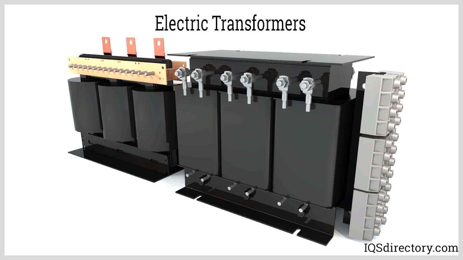
How Do Electric Transformers Work?
The concept of the function of the electric transformers is based on Faraday laws. The most central concept for the function of the transformers was introduced from the idea that magnetism can be produced by electricity.Therefore the opposite is true, which is that electricity can also be produced by magnetism.
Every electric mechanism contains magnetism. The electric transformers take use of the properties of the electricity to change the voltage of this same electricity either to make it high or to change it to a lower degree. The change in magnetism of the electric transformer either by any type of alteration of its strength produces a corresponding change which produces a type of electric force or power. During this process, when a conducting wire or any electric wire such as a copper wire is present and gets in contact with this process, electrons can be spread into this wire, resulting in the flow of electricity in the wire.
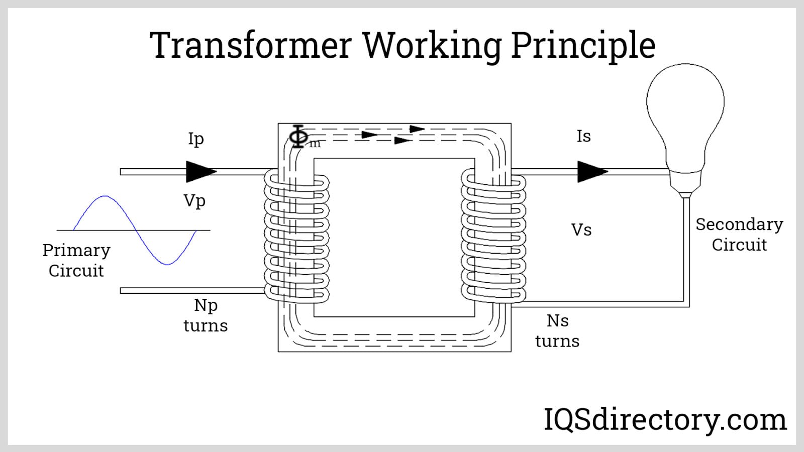
Electric transformers can be used to step up or to step down voltages depending on the coils that are wounded up around its core. The alternating current in the transformer results in the magnetism being alternating also. The electric transformer core contains an output wire which is placed around its coils and due to the fluctuation of the magnetism, a resulting current is induced into the wire.
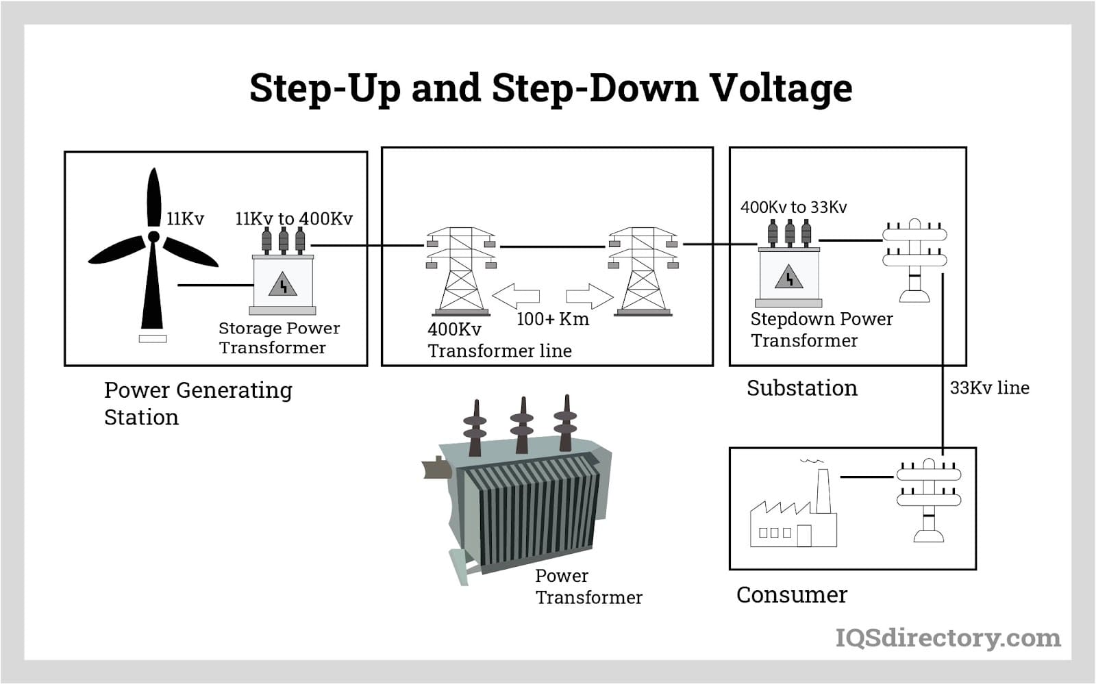
For electricity to be transferred along longer distances or from one power plant to another it has to be transported at higher voltages so as to cope with the long distance. The receiving location has to receive the electricity in lower voltages so as to avoid machine damages and other catastrophic electrical disasters which may tend to occur. To achieve this power plants have some smaller substations that help break down the high voltage into smaller increments and later step it down. In local areas, including residential homes, a transformer that steps down the high voltages to lower voltages is contained. This stepping down of voltage fits the voltage use of some of the household appliances including stoves, air conditioners, laptops, heaters, and televisions. In industrial areas there are machines and other appliances which use high voltage rates and to achieve this requirement, transformers that step up voltage are mostly contained in these areas.
To step down the voltage, the electric transformer must contain more wires on the primary wind and fewer wires on the secondary winding. And to step up the voltage the electric transformer must contain fewer wires on the primary wind and more wires on the secondary wind. There are very slim chances of an equal number of wires on both windings. There is no change in voltage as the same voltage is transferred from one area to another.
In every electric transformer despite its design, there is always loss of energy and this can be lost in the form of heat. Because the electric transformers are static they become hard to control and cool down. If this heat increases it results in the degrading or the damage of the insulation on the wiring of the electric transformers. Cooling of the electric transformers can be achieved in two ways: the use of air and oil. By cooling with air, air blasts are used to force the cooling air on the coils so as to bring the temperature down.
Circulating ambient air can also be used to carry the hot air particles away as it would be circulating inside the coils. When using oil, immersing the electric transformer in water or oil will cool down the hot temperatures. The two sets of coils or windings in an electric transformer are linked up by a magnetic core which is made up of iron or a ferrite compound wound laminated with copper or enamel coils.
Components of Electric Transformers
For an efficient process, the electric transformer consists of certain components, which include the ones named and described below.
Transformer Core
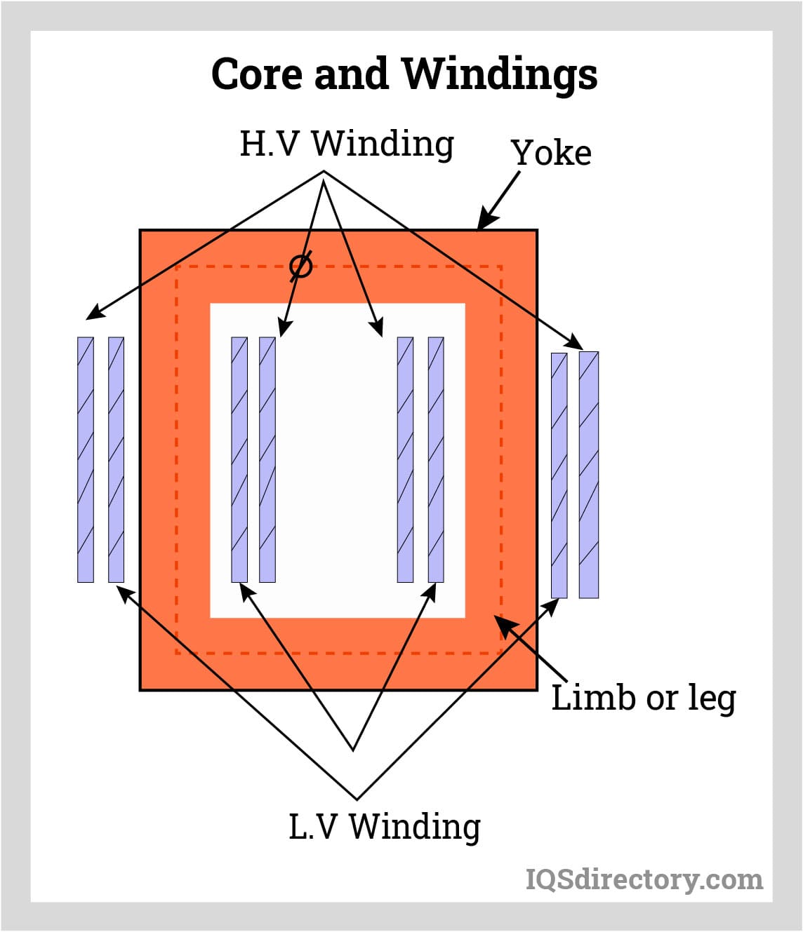
This component supports the primary and secondary windings as it also supports the electromagnetic flux by producing a low reluctance pathway. The core is made up of stacked thin sheets, which are assembled from high grade oriented steel and a thin insulating material separates them. The carbon content of the core steel is kept below a degree of 0.1% in order to minimize the hysteresis and the eddy currents in the system. Eddy currents can be reduced by alloying them with silicon. In the core of a three-phase transformer, each limb carries each phase’s primary and secondary winding. The yokes magnetically couple these limbs of the core. The core is constructed in two ways, including core and shell types. The core surrounds the windings in the shell type construction.
Transformer Winding
In each phase of a transformer, two sets of windings are found: the primary winding and the secondary winding. These windings are composed of many turns of copper or aluminum conductors which are insulated from each other and the transformer core. The way the windings are arranged and the winding type used all depends on the current rating, short circuit strength, the rise in temperature, the impedance, and the surges in voltage.
Of the secondary and primary windings, the one which is rated for a higher voltage is called an HV winding which means a higher voltage winding, whereas the one rated for a lower voltage is called an LV which means a lower voltage winding.
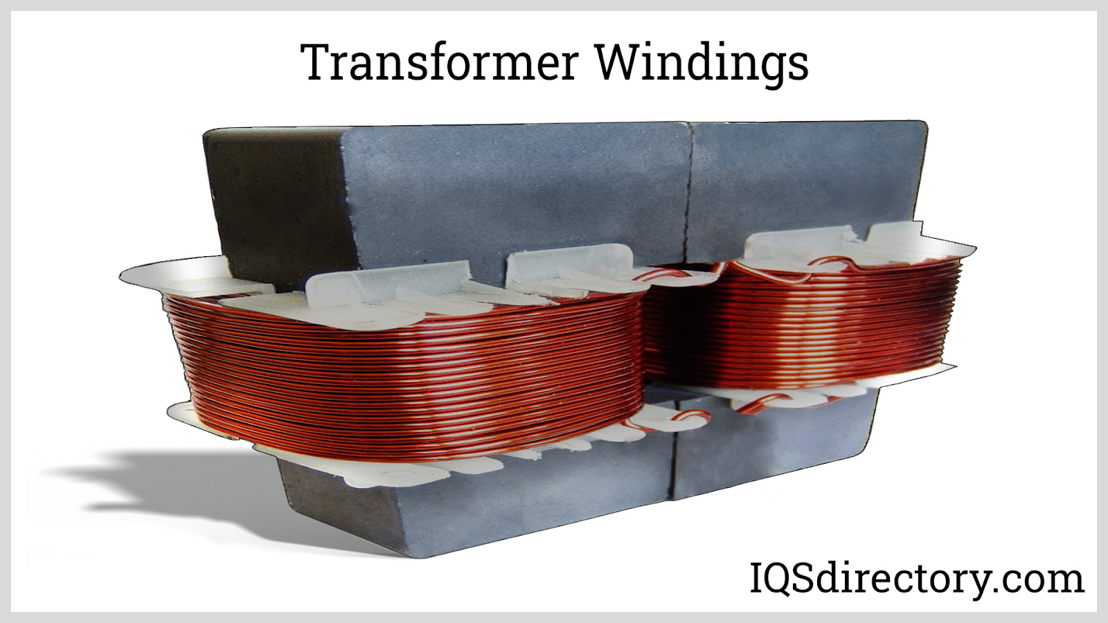
Depending on this property, the high voltage winding conductors contain materials that are thinner than the low voltage conductors as they surround the low voltage winding from outside. These low voltage windings are set in a closer way to the core. The high voltage windings are sandwiched between the low voltage coils in shell type transformers where the winding is split into several coils. In core type transformers, the windings are classified into four types and the choice of the winding type all depends on the current carrying capacity and the number of turns contained.
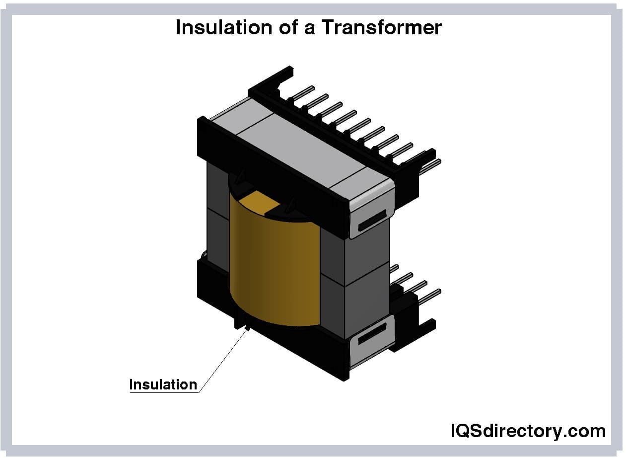
Insulation of a Transformer
Insulation is the most important requirement for transformers and in case they experience a failure, severe damages to the transformers can occur. These should have high dielectric strength and the ability to withstand high temperatures together with having high mechanical properties. Materials such as cotton, synthetic materials, and papers are used as insulators in transformers. These insulators should be placed between the windings and the core, between parts that carry current and between the windings.
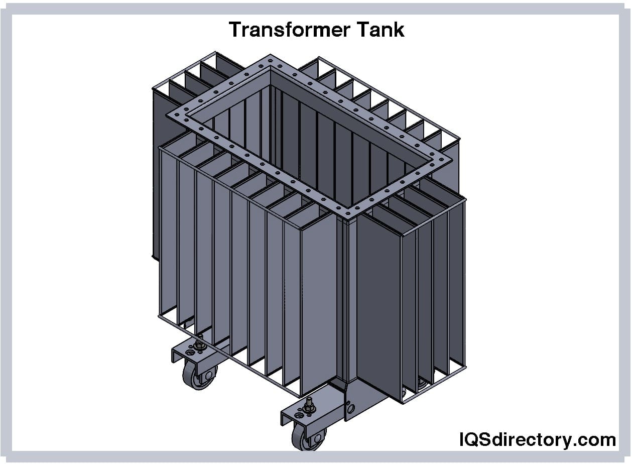
Transformer Tank
The tank serves two purposes: to protect the core and the windings from the outside environment. The other purpose is to contain oil and later also provide support for other transformer accessories.
These tanks are made by rolling steel plates to containers. In cases where weight has to be reduced aluminum sheets are used in place of the steel sheets. However this increases cost expenses as aluminum sheets are more expensive than steel sheets.
Transformer Oil
In oil immersed transformers, oil provides an added advantage as it provides added insulation between the conducting parts to cool down the transformer and detect faulty areas.
Terminal and Bushings
Terminals are present inside transformers and these are used for connecting incoming and outgoing cables. They are connected to bushes and the bushes are also connected to the ending of the windings. Bushings act as insulators, forming a barrier between the terminals and the tank. They also work as providers of safe passage for the conductor, which connects the terminals to the windings. Most of these are made up of materials, including epoxy resins and porcelain.
Oil Conservators
The oil conservator is located above the tank and the bushings. In some oil conservators, a rubber bladder is usually inserted. Its use is to provide enough space for oil expansion after the oil in the transformer had expanded and contracted due to an increase and decrease in temperature. The oil level inside the oil conservator is indicated by a level indicator fitted to the conservator for such use. Using a pipe the oil conservator is linked with the main tank.
Electric Transformer Breather
Breathers keep oil free from moisture and are found in oil immersed transformers. As the change in temperature causes the oil to expand and contract, air flows in and out of the conservator tank. This air should be free from moisture and this is made sure of by the breather. The breather is placed to the end of the pipe, which carries the air so that the air will be able to enter and exit the conservator through it as it clears the moisture contained. This moisture is removed from the air using the silica gel, which is present in the breathers thus resulting in moisture free air for the conservator.
Radiators and Fans
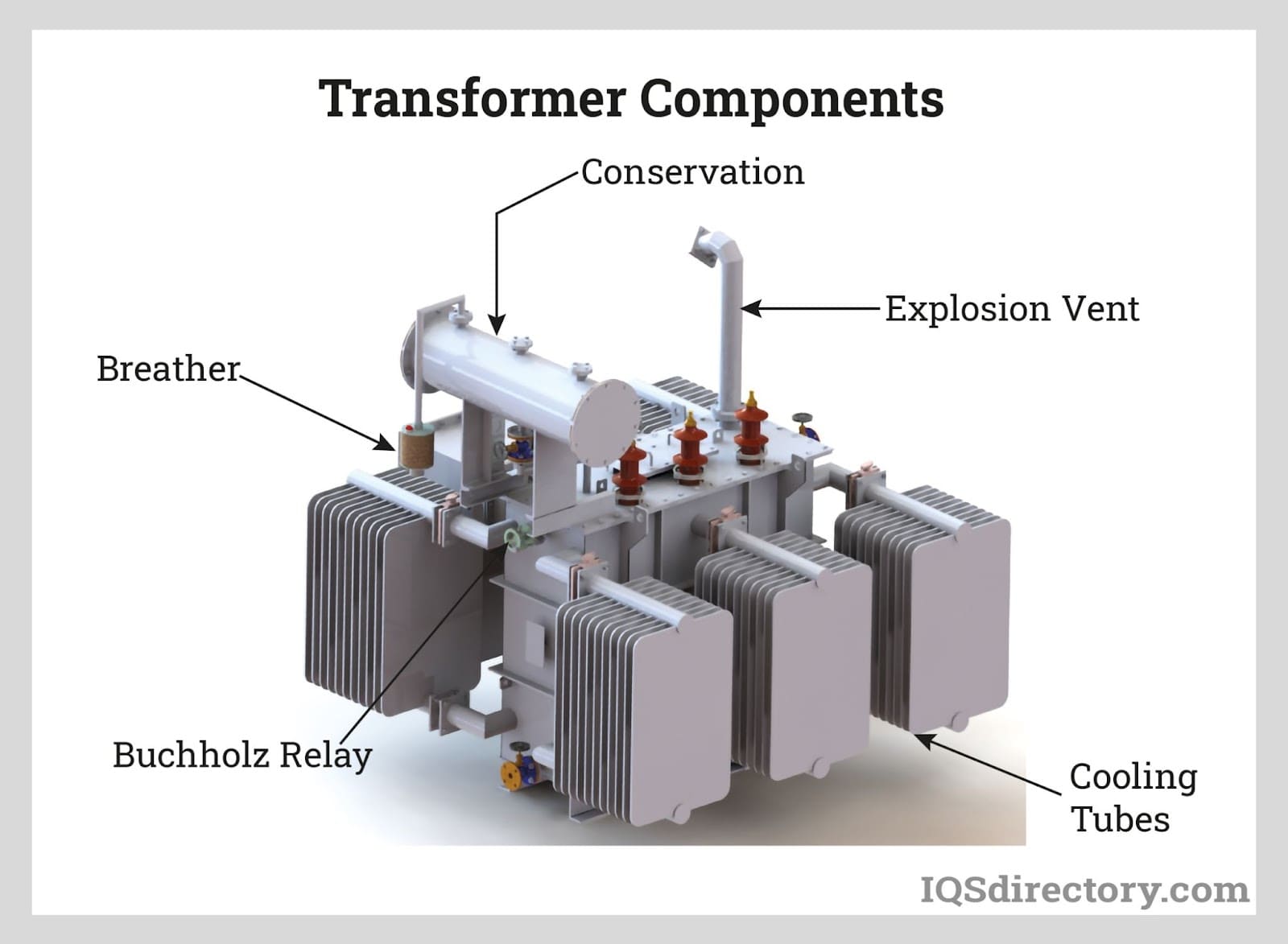
The heat found in the transformer is a result of the power dissipated during the power conversion process. The dry transformers are cooled by natural air. But there are oil immersed transformers that contain and follow a wide range of cooling methods. Cooling fans and radiators are placed on the transformer tank all depending on the power rating, how power is lost, and the requirements of the level of cooling for a certain transformer. The process follows the sequence that the heat generated or produced in the core and the windings are transferred to the surrounding transformer oil and then canceled out at the radiator. In bigger transformers, the process of forced cooling is implemented with the help of cooling radiators which are inserted in line with the radiators.
Explosion Vent
The explosion vent serves the purpose of being an emergency exit for oil and air gasses that are held inside a transformer. It is a pipe made up of metal, contained above the conservator tank, and has a diaphragm at one of its ends. The faults which occur due to the oil cause result in the pressure inside the tank rising to dangerous levels. In such situations the diaphragm gets destroyed at low pressure so as to release the forces from within the transformer to the outside atmosphere.
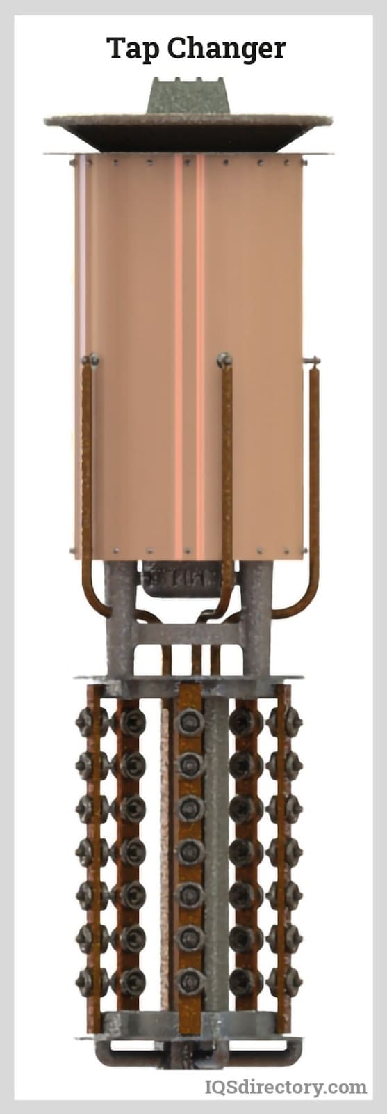
Tap Changers
In the adjustment of the secondary voltage of the electric transformers tap changers are used. These are made in a manner whereby they change the turns ratio of the transformer to the one required. Two types of tap changers are found and these include on load tap changers and off load tap changers. When the electric transformer does not supply any loads then the off load tap changers are used. The on load tap changers do not interrupt the current flow that heads towards the load.
Buchholz Relay
The Buchholz relay is used in oil immersed transformers and this kind can be rated over 500kVA. It is a relay made up of oil and gas and is used to sense faults when the parts of the electric transformer are immersed in oil. The Buchholz relay senses the gasses released when short circuits under the transformer oil generate enough heat that decomposes the oil into gas. As the gasses are sensed, the Buchholz relay activates an alarm circuit which then opens the circuit breaker supplying the current to the primary winding and interrupts the proper flow of the current.
Apart from these components explained above, other sensing instruments include pressure sensors and temperature sensors. Indicators, heat exchangers needed for efficient cooling and protection relays are also contained in some transformers, mainly huge transformers.
Chapter 2: Types of Electric Transformers
All transformers function under the concepts which come with faraday laws. But despite that they may be grouped or designed in different ways and types all depending on the applications of the certain selected electric transformer.
Iron Core Transformers
These types of electric transformers are classified as one of the most efficient because they contain a set of multiple iron plates which contain excellent magnetic properties.
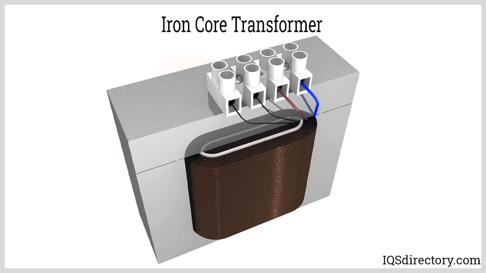
The sequence or process of magnetizing and demagnetizing happens very quickly in this type of electric transformer thus making a very much choice of a transformer. The sheets of the iron plates are usually made up of silicon steel with insulating paint on their surface so as to minimize the effect of heat produced during the working of the electric transformer.
Isolation Transformers
Because all electric transformers use the process of induction to convert electricity as compared to the use of a conductor, they can technically be all classified as isolation transformers. Transferring electrical power from one power source to another electrical device is the role of an isolation transformer. However despite the similarities with the other types of electrical transformers these can be distinguished from others because they are mainly used to isolate electricity or isolate the electrical device from the power source. Some of the applications of the isolation transformer include the use in uninterrupted power supplies, in robotics, in test and measurement systems, motor controls and industrial control panels and in data communication systems.
Ferrite Core Transformers
These types of electric transformers are able to control the loss of energy due to the use of transformers in high frequency applications. The permeable magnetic qualities of ferrite core transformers allow for this process. They contain an E type configuration and they can be fitted and shaped to any function.
Step Up Transformers
Due to their ability to convert lower voltages to higher voltages at the same time reducing amperage and the effects of resistance they are then perfect and adequate for application in areas such as power transforming and modification. The conversion of electrical energy allows it to travel through two phases of coils, with the second coil phase having a larger amount of windings. And this is defined as a complete coil assembly. Some of the uses of the step up transformer require a single coil of windings, whereas some uses require a tertiary set of windings.
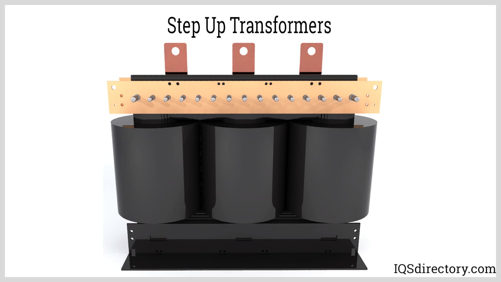
Above all electric transformers need two sets of coils to finish the conversion process. These two sets of coil windings have a core made from a ferrite compound or a laminated core wound containing enamel coils or uncovered copper. Step up transformers have their coil windings being constructed from aluminum, nickel, copper, chromium, and steel alloys thus making it as energy efficient as possible.
High Voltage Transformers
The voltage of a power transmission line refers to the measure of power transmission capacity in a transmission line. And these high voltage transformers are used to change the voltage of power lines in high voltage contexts. These types of transformers are used to handle high amounts of voltages in the range of 600 to 5000 volts where a volt refers to the measure of electromotive force. High voltage electric transformers have applications that include use for metering and providing protection in high voltage circuits. Some of the use areas are in electrostatic industrial and scientific areas.
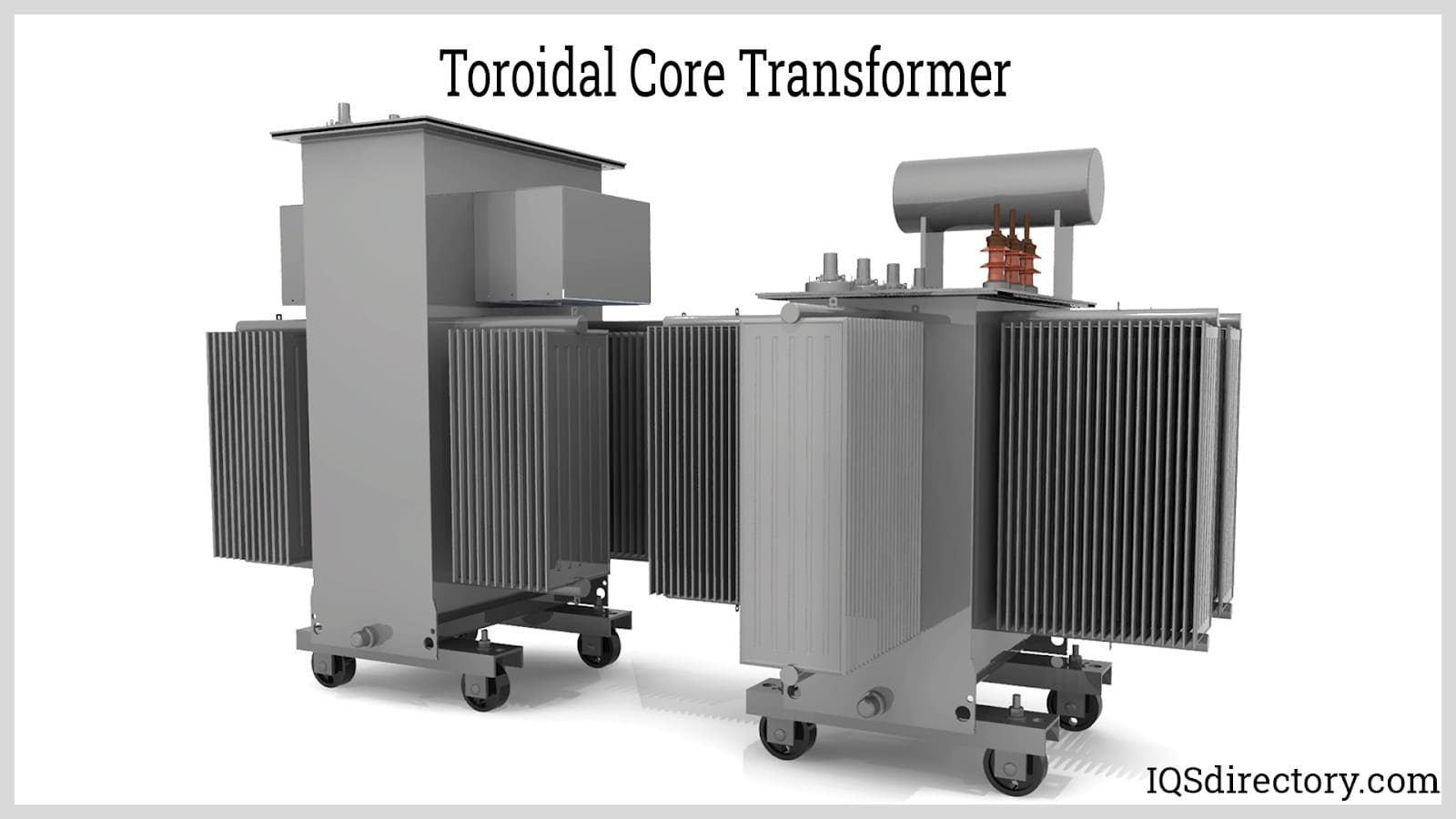
Toroidal Core Transformers
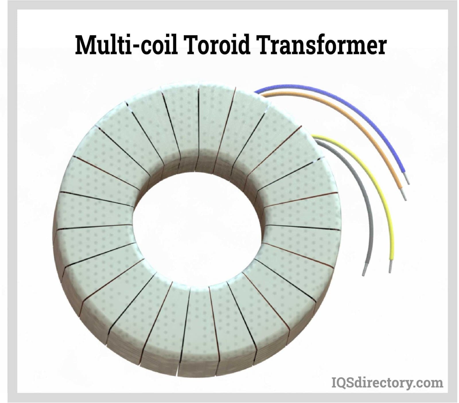
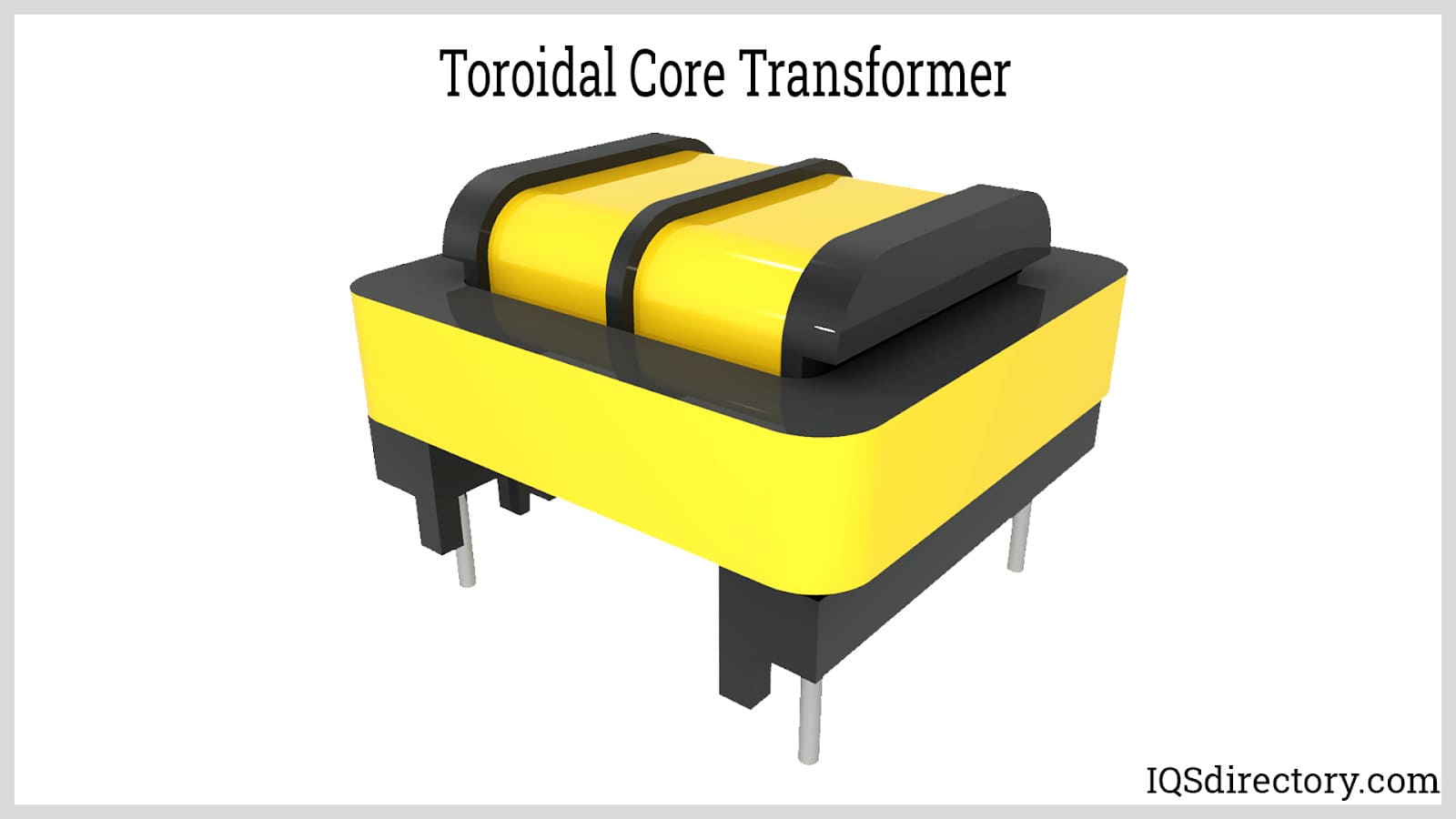
These types of transformers have a donut shape which helps to prevent induction leakage by creating high inductance in the system. It contains windings which are short and its weight is less as compared to other transformers which have the same rating. Because of their slow winding process, they are therefore expensive.
Air Coil Transformers
These do not contain a magnetic coil as a core and some areas of their application include radios and in small electronic devices. Its flux linkage is between two magnetically linked coils or windings which consist of the primary and the secondary windings. These transformers create flux with their windings and air passing through them. Low magnetic surfaces such as plastic tubing and cardboards are used to wound the coils.
Laminated Core Transformers
Sheets of iron and nickel that are laminated are used to make the core of laminated core transformers. This type which has nickel reduces energy losses when the winding is energized. The reduction of eddy currents is one of the main features of the laminated core transformer, which results in the increment of sufficient transfer of energy from the primary coil to the secondary coil.
Pulse Transformers
These types of electric transformers operate in a direct current mode because the flux density is conjunct but does not cross zero. The coupling of load resistance to a source of pulse power is one of the most common uses of pulse transformers. An example of this use would be in radar systems that may include radar transmitters systems of submarines or any other such. These radar transmitters employ an output power tube like a magnetron that needs high voltages and high impedance. Small types and designs of pulse transformers can create an electrical surge, making them suitable for use in telecommunications and detailed logic operations such as camera flashes and radar equipment. Medium sized transformers are used in applications that need electric circuits.
Current Transformers
Current transformers are best used in electrical transmission lines to measure the current or flow of electricity. Power transformers are used to control voltage whereas the current transformers can measure and control the movement for measuring purposes. Understanding these current transformers requires a little know-how on the nature of current as these electric transformers can also be used to control the flow of electricity to electronic devices.
Low Voltage Transformers
These are power transformers and they are used to change the voltage capacity which is contained in a low voltage electrical transmission line. Compared to high voltage transformers these low voltage transformers are small enough that they can be held between two fingers as they also have a low weight. In most cases, these low voltage transformers transfer or convert 120 volts into 12 volts or 24 volts.
Automatic Transformers
These types of electric transformers contain one winding, thus making them very cost effective as much as possible. The automatic or autotransformers contain one winding which acts both as a primary and secondary coil. It also contains three taps which are best used for electrical connections. These types of transformers have some advantages: they are smaller, less expensive and lighter. Automatic transformers can be used where electrical systems have different voltages.
Polyphase Transformers
Polyphase transformers contain three or more conductors, which can go as high as 15 phases. They contain multiple windings on the primary and secondary cores. Many of the polyphase transformers use a zig zag configuration, especially when they are grounded.
Zig Zag Transformers
This is a type of electric transformer that can be used to derive a reference point for use in underground systems. The zig zag transformer is used in a number of industries due to its ability to provide a neutral point for grounding purposes. Some of the areas of use include petrochemicals, power distribution, and automotives. Zig zag transformers contain a primary coil but do not have a secondary coil although they all in all consist of six coils on three separate cores. The windings of a zig zag transformer are in two halves because the way the two halves of the windings interconnect results in the difference in winding patterns while connecting the coils and the core.
Three Phase Transformers
This type of transformer can be classified among the polyphase transformers. It is more economical to have such a transformer even though it is possible to connect three single phase transformers together to make a single three phase transformer. A three phase transformer contains three sets of primary and secondary windings that can contain configurations of delta or star arranged in a format of delta to delta or star to star.
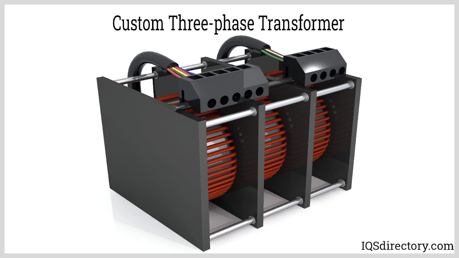
Three phase transformers are necessary for the directing and control of electrical current away from power lines into homes and places of business. A current transformer adjusts the amount of current that will flow from the electrical line into areas or equipment that will make use of it. Power transformers are usually most safe in operating electrical systems and single appliances.
Power Transformers
This type of transformer acts as a connection between the grid and generators and it is used to send energy to substations as it is huge in size. Since they are huge in size they require cooling, which is done using oil and cooling agents.
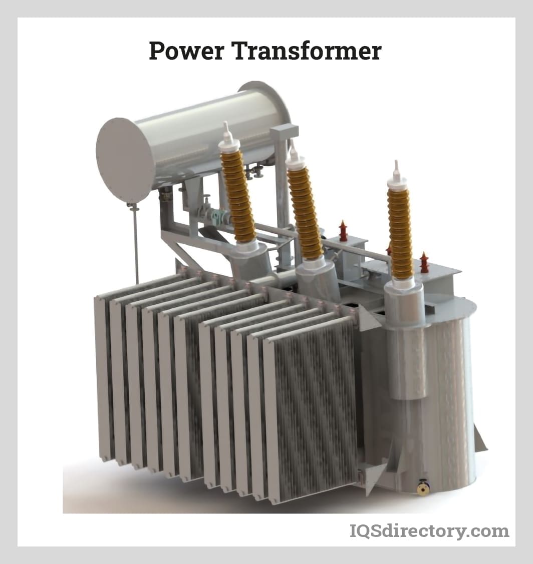
The system they use is costly as they use a three phase system, but despite the cost the system is more efficient than single phased systems. They are classified into three classes, all depending on their ratings in voltage.
Distribution Transformers
These can be used as step down transformers and they are used to turn high voltages to low voltages to transfer electrical energy through two coil stages whilst the second coil stage has fewer windings. The power produced varies whilst depending on geographical location.
Measurement Transformers
These are used to separate main power and voltage and later convert it to a smaller ratio.
Leading Manufacturers and Suppliers
GET YOUR COMPANY LISTED ABOVE
Chapter 3: Applications and Benefits of Electric Transformers
This chapter will discuss the applications and benefits of electric transformers.
Applications of Electric Transformers
Electric transformers play an important role in our daily lives as they either decrease or increase the electrical current to meet our daily needs in our use of electrical appliances. Some of the uses of electric transformers include controlling the flow of voltages during charging as unregulated voltage flow may result in electrical surges. And this may result in damage to the appliances which are being charged.
Steel production is another useful area for electric transformers. This is due to the fact that high voltages are required in the melting and welding and when it is now time for cooling low currents are needed after being produced by the electric transformer from the high voltages. In chemical processing the process of electrolysis is powered by transformers. To regulate the electrical current that powers the chemical reaction, transformers are needed. Some of the electroplated metals include aluminum, copper, and zinc. The current in this reaction is managed by the electric transformers.
Benefits of Electric Transformers
Electric transformers are cost efficient as the traditional transformer provides a cheap and very reliable method for voltage transmission and isolation. The sense that these transformers come in various types enables them to be used in various different areas, for example current transformers are used to step down currents for the measurement instruments. Transformers can be connected in a reverse manner in the sense that the same transformer can be wired to be a step up transformer or a step down transformer depending on how it is installed. To accommodate multiple input voltages, some electric transformers are fitted with multiple taps on the primary winding.
Drawbacks of Electric Transformers
Electric transformers require cooling due to the high temperatures which rise from the energy losses. These high temperatures result in the shortened lifespan of the insulating materials which are used in the windings. An electric transformer is not used to pass direct current. Electric transformers are hard when it comes to the issue of maintenance as most of them are damaged due to various reasons, including oil leakages, overloading and harmonics.
Conclusion
Electric transformers are basically machines that transfer electricity from one circuit to another by changing the levels in voltage but not in frequency. They are designed to use alternating current and thus the change in supply voltage is influenced by the change in supply current. They either step up or step down voltage levels, thus ensuring a safe and efficient power system in industrial and residential areas.
Leading Manufacturers and Suppliers
GET YOUR COMPANY LISTED ABOVE


![Toni Kroos là ai? [ sự thật về tiểu sử đầy đủ Toni Kroos ]](https://evbn.org/wp-content/uploads/New-Project-6635-1671934592.jpg)


