
Cheap Arduino mesh using RF24 radio modules
Communication between devices is key when you want to combine one or more devices. In my previous blog, I used I2C, Bluetooth and RF24 modules. The latter ones, the RF24 have a few advantages: they are cheap and do not need pairing. In my previous blog, I used them for a peer-to-peer (or better: Master-Slave) communication. This time, we will look at a mesh network using these devices.
This is part 9 of a series of blogs about device communication between Arduino, RaspberryPi etc:
Why using a Mesh Network?
In my current project, I have four or more potential slave modules. They all collect sensor data and one or two can execute commands. In a peer-to-peer solution, I would have to add four or more masters. That’s bad!
Lucky I came across this RF24Mesh library. It relies heavily on the RF24 libraries used in the previous blog:
“This class intends to provide a simple and seamless ‘mesh’ layer for sensor networks, allowing the automatic and dynamic configuration that can be customized to suit many scenarios.”
So in my project, I use one master and four slaves.
But how does it work?
Messages
The master device has some kind of DHCP like features. Slaves can ask for a unique number or renew it. In my example (based on the master and slave sketches provided inside the library) I concentrated on the messages. The messages are pretty simple:
// Payload from MASTER
struct payload_from_master {
  unsigned long counter;
  bool showLed;
};

// Payload to SLAVES
struct payload_from_slave {
  uint8_t nodeId;
  unsigned long timer;
  bool ledShown;
};
The message from the master contains a simple counter which increases with every call. And it contains the command, a boolean which tells each slave to toggle a led (on slave digital pin 5).
The message from each slave contains the unique id of the slave, a value of the timer running on the slave and a boolean which tells the master if the slave has toggled the led.
I keep it simple regarding the message. All slaves get the same message. This saves me a lot of administration (who needs to get what). So the master acts more like a broker.
Master logic
So in the end, the logic on the master in the loop is pretty simple:
- The default mesh logic is executed.
- The network is checked for an incoming message (from a slave)
- Any available message is printed
- Then every 5 seconds…
- The DHCP table is printed (this is optional)
- And we send a message to each slave
Slave logic
The slave logic in the loop is even more simple:
- The default mesh logic is executed.
- Then every two seconds…
- A message for the master is constructed and send
- If the transmission fails, a renewal of the DHCP address is requested.
- Meanwhile, we check for messages from the master.
- If a message is available, we react to it.
The only thing to keep in mind with the slave is that the sketch has to be made unique for each slave, we have to provide a unique node id.
The code
This is what’s needed for the master:
/*
* This example sketch shows how to manually configure
* a node via RF24Mesh as a master node, which
* will receive all data from sensor nodes and transmit
* the same message to all slaves.
*/
#include "RF24Network.h"
#include "RF24.h"
#include "RF24Mesh.h"
#include <SPI.h>
//Include eeprom.h for AVR (Uno, Nano) etc. except ATTiny
#include <EEPROM.h>
/***** Configure the chosen CE,CS pins *****/
RF24 radio(7,8);
RF24Network network(radio);
RF24Mesh mesh(radio,network);
// Payload from MASTER
struct payload_from_master {
unsigned long counter;
bool showLed;
};
// Payload to SLAVES
struct payload_from_slave {
uint8_t nodeId;
unsigned long timer;
bool ledShown;
};
uint32_t displayTimer = 0;
uint32_t counter = 0;
bool showLed;
void setup() {
Serial.begin(115200);
// Set the nodeID to 0 for the master node
mesh.setNodeID(0);
Serial.println(mesh.getNodeID());
// Connect to the mesh
mesh.begin();
}
void loop() {
// Call mesh.update to keep the network updated
mesh.update();
// In addition, keep the 'DHCP service' running
//on the master node so addresses will
// be assigned to the sensor nodes
mesh.DHCP();
// Check for incoming data from the sensors
if(network.available()){
RF24NetworkHeader header;
network.peek(header);
payload_from_slave payload;
switch(header.type){
// Display the incoming millis() values from sensor nodes
case 'M': network.read(header, &payload, sizeof(payload));
Serial.print(" On slave:");
Serial.print(payload.nodeId);
Serial.print(" millis:");
Serial.print(payload.timer);
Serial.print(" Led shown:");
Serial.println(payload.ledShown);
break;
default: network.read(header,0,0);
Serial.println(header.type);
break;
}
}
// Meanwhile, every 5 seconds...
if(millis() - displayTimer > 5000){
//// SHOW DHCP TABLE - BEGIN
displayTimer = millis();
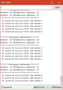
Serial.println(" ");
Serial.println(F("********Assigned Addresses********"));
for(int i=0; i<mesh.addrListTop; i++){
Serial.print("NodeID: ");
Serial.print(mesh.addrList[i].nodeID);
Serial.print(" RF24Network Address: 0");
Serial.println(mesh.addrList[i].address,OCT);
}
Serial.println(F("**********************************"));
//// SHOW DHCP TABLE - BEGIN
//// Send same master message to all slaves - BEGIN
showLed = !showLed;
for(int i=0; i<mesh.addrListTop; i++){
counter++;
payload_from_master payload = {counter, showLed};
RF24NetworkHeader header(mesh.addrList[i].address, OCT);
int x = network.write(header, &payload, sizeof(payload));
}
//// Send same master message to all slaves - end
}
}
And this is the code for a slave:
/*
 * This example sketch shows how to manually
 * configure a client node via RF24Mesh,
 * and send data to the master node and
 * receive data from master node.
 */

#include "RF24.h"
#include "RF24Network.h"
#include "RF24Mesh.h"
#include <SPI.h>
#include <EEPROM.h>

/**** Configure the nrf24l01 CE and CS pins ****/
RF24 radio(7, 8);
RF24Network network(radio);
RF24Mesh mesh(radio, network);

/** User Configuration per node: nodeID **/
#define nodeID 42

// Payload to MASTER
struct payload_from_master {
  unsigned long counter;
  bool showLed;
};

// Payload from SLAVE
struct payload_from_slave {
  uint8_t nodeId;
  uint32_t timer;
  bool ledShown;
};

bool showLed;
uint32_t sleepTimer;

void setup() {
  pinMode(5, OUTPUT);
  Serial.begin(115200);
  // Set the nodeID manually
  mesh.setNodeID(nodeID);
  // Connect to the mesh
  Serial.println(F("Connecting to the mesh..."));
  mesh.begin();
}

void loop() {
  mesh.update();

  //// Send to the master node every two seconds - BEGIN
  if (millis() - sleepTimer >= 2000) {
    sleepTimer = millis();
    payload_from_slave payload = {nodeID, sleepTimer, showLed};

    // Send an 'M' type message containing the current millis()
    if (!mesh.write(&payload, 'M', sizeof(payload))) {
    // If a write fails, check connectivity to the mesh network
      if ( ! mesh.checkConnection() ) {
      //refresh the network address
      Serial.println("Renewing Address");
      mesh.renewAddress();
    } else {
      Serial.println("Send fail, Test OK");
    }
  } else {
    Serial.print("Send OK: ");
    Serial.println(payload.timer);
  }
}
//// Send to the master node every two seconds - END

  //// Receive a message from master if available - START
  while (network.available()) {
    RF24NetworkHeader header;
    payload_from_master payload;
    network.read(header, &payload, sizeof(payload));
    Serial.print("Received packet #");
    Serial.print(payload.counter);
    Serial.print(" Show led=");
    Serial.println(payload.showLed);

    showLed = payload.showLed;

    if (payload.showLed) {
      digitalWrite(5, HIGH);
    }
    else {
      digitalWrite(5, LOW);
    }
  }
  //// Receive a message from master if available - START
}
So add some LED on port 5 of each slave module and see all nodes flash on and off every five seconds. Then you know your Mesh is running.
Reliable?
The communication is very reliable, once it is running. Once in a while, it looks like the communication is not starting up that well. I have no idea why but after putting new sketches on the modules, everything is working again. But sometimes just waiting is good enough.
An impression of the working solution is seen on (sorry for the flickering led):
What is your experience? Please put it in the comments.
Share this:
Vind ik leuk:
Vind-ik-leuk
Laden…


![Toni Kroos là ai? [ sự thật về tiểu sử đầy đủ Toni Kroos ]](https://evbn.org/wp-content/uploads/New-Project-6635-1671934592.jpg)


