
Azure Hub And Spoke 2.0
I have recently had a couple of recent conversations that have made me reconsider the way we traditionally implement the hub and spoke Virtual Network design in Azure, which has some limitations. The idea is to introduce a relatively simple but powerful modification to the design that achieves these objectives:
- Granular control of prefixes advertised via ExpressRoute or BGP site-to-site IPsec connections. Today all the spoke VNet prefixes are advertised to on-premises and to other regions, but instead the goal is advertising only a summary route per region
- Have a more flexible architecture where spokes can be peered to multiple hubs for redundancy
- Simplify the design configuration, by removing the need as much as possible to overwrite routes in Azure subnets
TL,DR: The main modification introduced to the traditional design is the absence of gateway transit in the VNet peerings (UseRemoteGateways / AllowGatewayTransit settings) between the hub and the spoke VNets, as well as having specific prefixes advertised to ExpressRoute and BGP S2S VPNs via Azure Route Servers in each region.
Mục Lục
When to use this design?
Before getting into the weeds, let’s first clarify to which network design this pattern is applicable. Using the Azure Network architecture framework that I first published in this post, you initially start from the most flexible design which is Virtual WAN with indirect spokes (design number 1 in the diagram below), and to simplify the architecture you can optionally collapse your tiers to either design 2 (Virtual WAN, typically when you don’t need sophisticated functionality in the hub) or design 3 (Hub and Spoke, for example when you need maximum flexibility to bring network services to the hub):
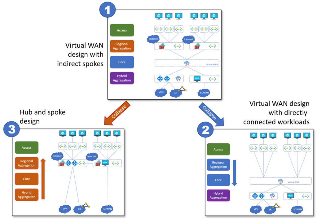
A deep discussion of when to use each design is out of the scope here. In this post, we will be focusing on design number 3, often called “traditional hub and spoke”.
The topology
I have used the Megaport Cloud Router to provision my ExpressRoute connections, and Google Cloud to simulate my on-prem environment. The initial test bed looks like this (you can see the exact Azure CLI commands I used to deploy the topology in https://github.com/erjosito/azcli/blob/master/routeserver_2hubs.azcli):

Traditional behavior
In the traditional hub and spoke behavior, the VNet peerings will be configured with gateway transit enabled (as explained in https://learn.microsoft.com/azure/virtual-network/virtual-network-peering-overview#gateways-and-on-premises-connectivity). Spoke VNets will have route tables associated to their subnets pointing to the hub NVA (no NVA redundancy in the lab for simplicity, otherwise you would probably have them pointing to an internal Load Balancer). Here you can see the effective routes for NIC in a spoke in region 1, not showing the routes learnt by the VPN on ExpressRoute gateways (since the route table should have the option to disable gateway route propagation):
❯ az network nic show-effective-route-table --ids $spoke11_vm_nic_id -o table
Source    State    Address Prefix    Next Hop Type      Next Hop IP
--------  -------  ----------------  -----------------  -------------
Default   Active   10.1.16.0/24      VnetLocal
Default   Active   10.1.0.0/20       VNetPeering
Default   Invalid  0.0.0.0/0         Internet
User      Active   0.0.0.0/0         VirtualAppliance   10.1.1.4
The NVAs in the hub get to know where to reach everything: they need to have gateway propagation enabled to receive the routes from VPN/ExpressRoute gateways and from the Route Server (all these routes will be marked as being sourced by a VirtualNetworkGateway). Below you can see the effective routes of the NVA in region 1:
❯ az network nic show-effective-route-table --ids $hub1_nva1_nic0_id -o table
Source                 State    Address Prefix    Next Hop Type          Next Hop IP
---------------------  -------  ----------------  ---------------------  -------------
Default                Active   10.1.0.0/20       VnetLocal
Default                Active   10.1.16.0/24      VNetPeering
Default                Active   10.1.17.0/24      VNetPeering
VirtualNetworkGateway  Active   10.251.0.0/16     VirtualNetworkGateway  10.1.3.4
VirtualNetworkGateway  Active   10.251.0.0/16     VirtualNetworkGateway  10.1.3.5
VirtualNetworkGateway  Active   10.2.0.0/16       VirtualNetworkGateway  10.1.1.4
VirtualNetworkGateway  Active   10.1.0.0/16       VirtualNetworkGateway  10.1.1.4
VirtualNetworkGateway  Active   10.2.16.0/24      VirtualNetworkGateway  10.2.146.34
VirtualNetworkGateway  Active   10.2.17.0/24      VirtualNetworkGateway  10.2.146.34
VirtualNetworkGateway  Active   10.4.2.0/24       VirtualNetworkGateway  10.2.146.34
Default                Active   0.0.0.0/0         Internet
Default                Active   10.0.0.0/8        None
Default                Active   100.64.0.0/10     None
Default                Active   172.16.0.0/12     None
Default                Active   25.48.0.0/12      None
Default                Active   25.4.0.0/14       None
Default                Active   198.18.0.0/15     None
Default                Active   157.59.0.0/16     None
Default                Active   192.168.0.0/16    None
Default                Active   25.33.0.0/16      None
Default                Active   40.109.0.0/16     None
Default                Active   104.147.0.0/16    None
Default                Active   104.146.0.0/17    None
Default                Active   40.108.0.0/17     None
Default                Active   23.103.0.0/18     None
Default                Active   25.41.0.0/20      None
Default                Active   20.35.252.0/22    None
Default                Active   10.2.0.0/20       VNetGlobalPeering
Remarks:
- The routes from the spoke VNets in the remote region (
10.2.16.0/24and10.2.17.0/24) are reflected by the ExpressRoute edge router (MSEE or Microsoft Enterprise Edge) and learned in hub 1. - You can see that there are some regional summaries advertised by the local NVA:
10.1.0.0/16and10.2.0.0/16. The local prefixes (10.1.0.0/16in this example) are not a problem because they are overridden by the more specific routes from the VNet peering, but the summaries for the remote regions (10.2.0.0/16) will have to be overridden by UDRs (or use some encapsulation between the NVAs in different regions, see this post for more details). We will see this overriding later in this post.
We can check that the ExpressRoute gateway in region 1 sees the spoke routes from region 2 with the AS path 12076 12076 (12076 is the ASN associated to ExpressRoute MSEEs):
❯ az network vnet-gateway list-learned-routes -n $hub1_ergw_name -g $rg --query 'value[].{LocalAddress:localAddress, Peer:sourcePeer, Network:network, NextHop:nextHop, ASPath: asPath, Origin:origin, Weight:weight}' -o table             LocalAddress    Peer       Network            ASPath              Origin    Weight    NextHop
--------------  ---------  -----------------  ------------------  --------  --------  ---------
10.1.3.12       10.1.3.12  10.1.0.0/20                            Network   32768
10.1.3.12       10.1.3.12  10.1.16.0/24                           Network   32768
10.1.3.12       10.1.3.12  10.1.17.0/24                           Network   32768
10.1.3.12       10.1.0.4   10.251.0.0/16      65100               IBgp      32768     10.1.3.4
10.1.3.12       10.1.0.5   10.251.0.0/16      65100               IBgp      32768     10.1.3.4
10.1.3.12       10.1.0.4   10.1.0.0/16        65001               IBgp      32768     10.1.1.4
10.1.3.12       10.1.0.5   10.1.0.0/16        65001               IBgp      32768     10.1.1.4                                                                                                                                              10.1.3.12       10.1.0.4   10.2.0.0/16        65001-65002         IBgp      32768     10.1.1.4
10.1.3.12       10.1.0.5   10.2.0.0/16        65001-65002         IBgp      32768     10.1.1.4
10.1.3.12       10.1.3.6   169.254.168.16/30  12076-133937        EBgp      32779     10.1.3.6
10.1.3.12       10.1.3.7   169.254.168.16/30  12076-133937        EBgp      32779     10.1.3.7
10.1.3.12       10.1.3.6   169.254.168.20/30  12076-133937        EBgp      32779     10.1.3.6
10.1.3.12       10.1.3.7   169.254.168.20/30  12076-133937        EBgp      32779     10.1.3.7
10.1.3.12       10.1.3.6   10.2.0.0/20        12076-12076         EBgp      32779     10.1.3.6
10.1.3.12       10.1.3.7   10.2.0.0/20        12076-12076         EBgp      32779     10.1.3.7
10.1.3.12       10.1.3.6   10.2.16.0/24       12076-12076         EBgp      32779     10.1.3.6
10.1.3.12       10.1.3.7   10.2.16.0/24       12076-12076         EBgp      32779     10.1.3.7
10.1.3.12       10.1.3.6   10.2.17.0/24       12076-12076         EBgp      32779     10.1.3.6
10.1.3.12       10.1.3.7   10.2.17.0/24       12076-12076         EBgp      32779     10.1.3.7
10.1.3.12       10.1.3.6   169.254.68.112/29  12076-133937        EBgp      32779     10.1.3.6
10.1.3.12       10.1.3.7   169.254.68.112/29  12076-133937        EBgp      32779     10.1.3.7
10.1.3.12       10.1.3.6   10.4.2.0/24        12076-133937-16550  EBgp      32779     10.1.3.6
10.1.3.12       10.1.3.7   10.4.2.0/24        12076-133937-16550  EBgp      32779     10.1.3.7
As described earlier, I am deploying the ExpressRoute connections using Megaport’s Cloud Router (MCR). We can verify that the MCR sees both the /16 summary routes and the more specific /24 routes for the spokes. I am using this script to provision, troubleshoot and delete MCRs using Megaport’s REST API:
❯ $megaport_script_path -q -s=jomore-${hub1_er_pop} -a=bgp_routes | jq -r '.[] | {prefix,best,source,asPath} | join("\t")'
10.1.0.0/20     false   169.254.168.22  12076
10.1.0.0/20     true    169.254.168.18  12076
10.1.0.0/16     true    169.254.168.18  12076
10.1.16.0/24    false   169.254.168.22  12076
10.1.16.0/24    true    169.254.168.18  12076
10.1.17.0/24    false   169.254.168.22  12076
10.1.17.0/24    true    169.254.168.18  12076
10.2.0.0/20     false   169.254.168.22  12076
10.2.0.0/20     true    169.254.168.18  12076
10.2.0.0/16     true    169.254.168.18  12076
10.2.16.0/24    false   169.254.168.22  12076
10.2.16.0/24    true    169.254.168.18  12076
10.2.17.0/24    false   169.254.168.22  12076
10.2.17.0/24    true    169.254.168.18  12076
10.251.0.0/16   true    169.254.168.18  12076
169.254.68.112/29       true    0.0.0.0
169.254.168.16/30       true    0.0.0.0
169.254.168.20/30       true    0.0.0.0
Notice that all the /24 prefixes from the spoke VNets are there too, as expected. Finally, these are the routes that arrive to the on-premises network (simulated with a VPC in Google Cloud):
❯ gcloud compute routers get-status $router1_name --region=$region1 --format=json | jq -r '.result.bestRoutesForRouter[]|{destRange,routeType,nextHopIp} | join("\t")'
10.1.0.0/16             BGP     169.254.68.114
10.1.0.0/20             BGP     169.254.68.114
10.1.16.0/24            BGP     169.254.68.114
10.1.17.0/24            BGP     169.254.68.114
10.2.0.0/16             BGP     169.254.68.114
10.2.0.0/20             BGP     169.254.68.114
10.2.16.0/24            BGP     169.254.68.114
10.2.17.0/24            BGP     169.254.68.114
10.251.0.0/16           BGP     169.254.68.114
169.254.68.112/29       BGP     169.254.68.114
169.254.168.16/30       BGP     169.254.68.114
169.254.168.20/30       BGP     169.254.68.114
Again, the on-premises router would see all the individual spoke prefixes, which might not be a good idea if there are many spoke VNets in Azure. For example, in this specific case Google Cloud has a limit of 100 for the number of routes received to (https://cloud.google.com/network-connectivity/docs/router/quotas#limits). Consequently, we would have a problem if we had 100 spoke VNets or more in Azure.
Disabling Gateway Transit
After changing the peerings between the spoke and hub VNets to not use gateway transit (disabling the settings UseRemoteGateways and AllowGatewayTransit), this is what the effective routes in the NVA in hub 1 now look like:
❯ az network nic show-effective-route-table --ids $hub1_nva1_nic0_id -o table
Source                 State    Address Prefix    Next Hop Type          Next Hop IP
---------------------  -------  ----------------  ---------------------  -------------
Default                Active   10.1.0.0/20       VnetLocal
Default                Active   10.1.16.0/24      VNetPeering
Default                Active   10.1.17.0/24      VNetPeering
VirtualNetworkGateway  Active   10.251.0.0/16     VirtualNetworkGateway  10.1.3.4
VirtualNetworkGateway  Active   10.251.0.0/16     VirtualNetworkGateway  10.1.3.5
VirtualNetworkGateway  Active   10.1.0.0/16       VirtualNetworkGateway  10.1.1.4
VirtualNetworkGateway  Active   10.4.2.0/24       VirtualNetworkGateway  10.2.146.34
VirtualNetworkGateway  Invalid  10.2.0.0/16       VirtualNetworkGateway  10.1.1.4
Default                Active   0.0.0.0/0         Internet
Default                Active   10.0.0.0/8        None
Default                Active   100.64.0.0/10     None
Default                Active   172.16.0.0/12     None
Default                Active   25.48.0.0/12      None
Default                Active   25.4.0.0/14       None
Default                Active   198.18.0.0/15     None
Default                Active   157.59.0.0/16     None
Default                Active   192.168.0.0/16    None
Default                Active   25.33.0.0/16      None
Default                Active   40.109.0.0/16     None
Default                Active   104.147.0.0/16    None
Default                Active   104.146.0.0/17    None
Default                Active   40.108.0.0/17     None
Default                Active   23.103.0.0/18     None
Default                Active   25.41.0.0/20      None
Default                Active   20.35.252.0/22    None
User                   Active   10.2.0.0/16       VirtualAppliance       10.2.1.4
Default                Active   10.2.0.0/20       VNetGlobalPeering
Note that a static route has been added as well to override the summary prefix for the spoke VNets in region 2 (10.2.0.0/16), that is why you can see that the previous route for 10.2.0.0/16 shows as Invalid. This summary route now will work now, because the more specific /24 prefixes are not there anymore (before we would have had to override every. single. spoke.).
Now we can have a look at the onprem routes:
❯ gcloud compute routers get-status $router1_name --region=$region1 --format=json | jq -r '.result.bestRoutesForRouter[]|{destRange,routeType,nextHopIp} | join("\t")'
10.1.0.0/16     BGP     169.254.68.114
10.1.0.0/20     BGP     169.254.68.114
10.2.0.0/16     BGP     169.254.68.114
10.2.0.0/20     BGP     169.254.68.114
10.251.0.0/16   BGP     169.254.68.114
169.254.68.112/29       BGP     169.254.68.114
169.254.168.16/30       BGP     169.254.68.114
169.254.168.20/30       BGP     169.254.68.114
Here again the spoke prefixes are gone, so we can be confident that adding new spoke VNets in Azure will not compromise the scale of our onprem routers (Google virtual routers in the example).
Avoiding the need for UDRs in the spokes
As described at the beginning of the article, the basic design requires a route table associated to every spoke VNet to send traffic to the NVA appliance(s) in the same region containing a single 0.0.0.0/0 route and disabling gateway propagation.
An additional route server could be introduced in every region if no UDRs are desired, following the pattern in Different Route Servers to advertise routes to VNGs and VNets (Azure docs). This second route server would inject the 0.0.0.0/0 to every spoke VNet.
Dual-homing spokes to multiple hubs
Since the VNet peerings between hubs and spokes do not require the gateway transit setting, they can be connected to more than one hub VNet. This design would result in higher resiliency, since a given spoke can be accessed via more than one region, but would reduce the scalability of any given hub.
Scalability
The main scalability limit of this design is going to be the route table in the gateway subnet where VPN and ExpressRoute gateways are deployed. In every hub you will need a route table associated to its corresponding GatewaySubnet with one route for each directly peered spoke. You cannot use summary routes because the VNet peerings will introduce more specific routes corresponding to the prefixes defined in every spoke VNet.
Since the limit of route tables is 400 routes at the time of this writing (see Azure Networking Limits), the maximum number of spokes that you can attach to any given hub doesn’t change with this pattern and stays 400.
Downsides
So far, we have spoken about benefits, particularly the more granular control of what gets advertised from Azure to other network locations (on-premises networks and other Azure regions). As with every design, this one comes with its own set of caveats:
- The main drawback is the complexity associated to the need to maintain an NVA that feeds the Azure Route Server with BGP routes. If your design already incorporates a Network Virtual Appliance able to speak BGP, and you are familiar with this protocol, this additional complexity might be negligible. If on the contrary you have an NVA that doesn’t support BGP (like Azure Firewall) or you are not willing to swim through the BGP waters, this design might be overly complex for you.
- A limitation of this design is the fact that Azure Route Server doesn’t support IPv6 today (https://learn.microsoft.com/azure/route-server/route-server-faq#does-azure-route-server-support-ipv6), so if you need IPv6 in your VNet, this is not the design you are looking for (read with a Jedi hand move).
Adding up
Azure Route Server gives you a finer control on what you want to advertise over BGP with Azure, making the use of the gateway transit settings in VNet peerings unnecessary, or even undesirable in certain situations. Consider this option the next time you are confronted with a hub and spoke topology in Azure.
Please let me know in the comments below if you see other benefits or disadvantages of this design that I haven’t described.
Thanks for reading!
Share this:
Like this:
Like
Loading…


![Toni Kroos là ai? [ sự thật về tiểu sử đầy đủ Toni Kroos ]](https://evbn.org/wp-content/uploads/New-Project-6635-1671934592.jpg)


