10 Business Process Modelling Techniques | GetSmarter Blog
Mục Lục
10 Business Process Modelling Techniques Explained, With Examples
Business process modelling isn’t a new concept. However, when implemented effectively it can help optimise business process and identify any challenges in your established systems. Business process modelling gives you the opportunity to map out all of the steps in your business process, giving you a visual reference so that you can better understand, analyse and improve workflows.
In his white paper ‘10 Perilous misconceptions of censuring current state mapping & analysis’, James Proctor debunks a number of misconceptions about business process modelling, such as “[w]e already know what we do, let’s just skip to what we need to be doing going forward – so no need to map and analyze existing processes.” He explains that business process modelling should begin by answering five questions that will provide a framework to start thinking about how you do business.
These questions are:
- What are you currently doing?
- What are you currently doing that is not needed?
- What are you currently doing that can be improved?
- What are you not doing that you know you should be doing?
- What are you not doing that you don’t know you should be doing?
When it comes to describing what your business does, you could probably sum it up in a matter of sentences. However, the reality is that it can only achieve its purpose by your team working together to complete a series of tasks in succession, in order to produce a final result. Business process modelling allows you to map out all of these steps into a visual representation, so that you can better understand, analyse, and improve the workflow or process.
Fundamentally, business process modelling involves identifying, defining, and representing a process in its entirety, in order to aid communication of that process. It also has the following benefits:
- Allows you to identify tasks that are redundant and remove them
- You can spot bottlenecks in the process and improve process efficiency by eliminating them
- Efficient processes can be identically repeated, even when a new staff member must perform that part of the process
There are several techniques in business process modelling:
1. Business process modelling notation (BPMN)
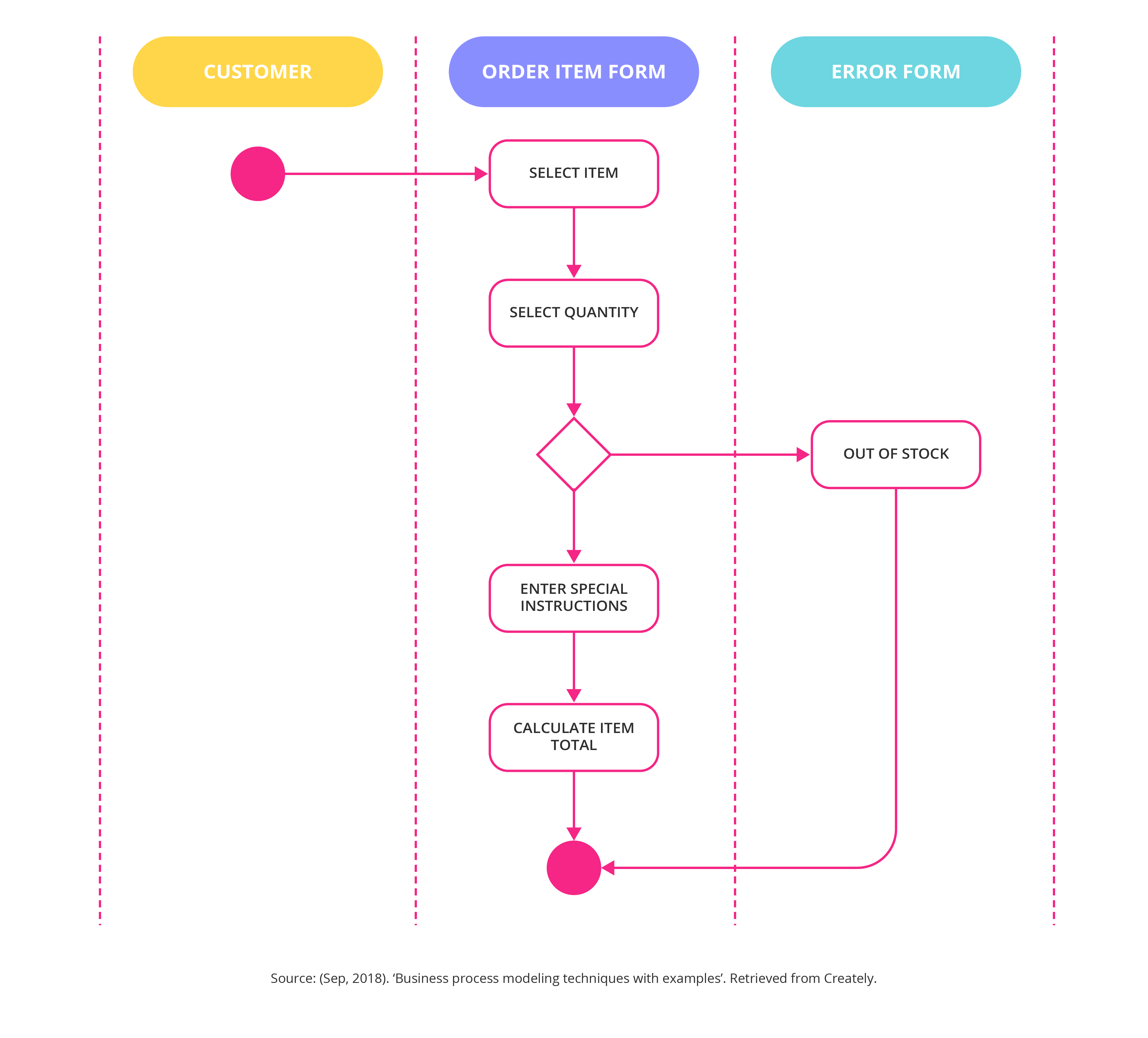
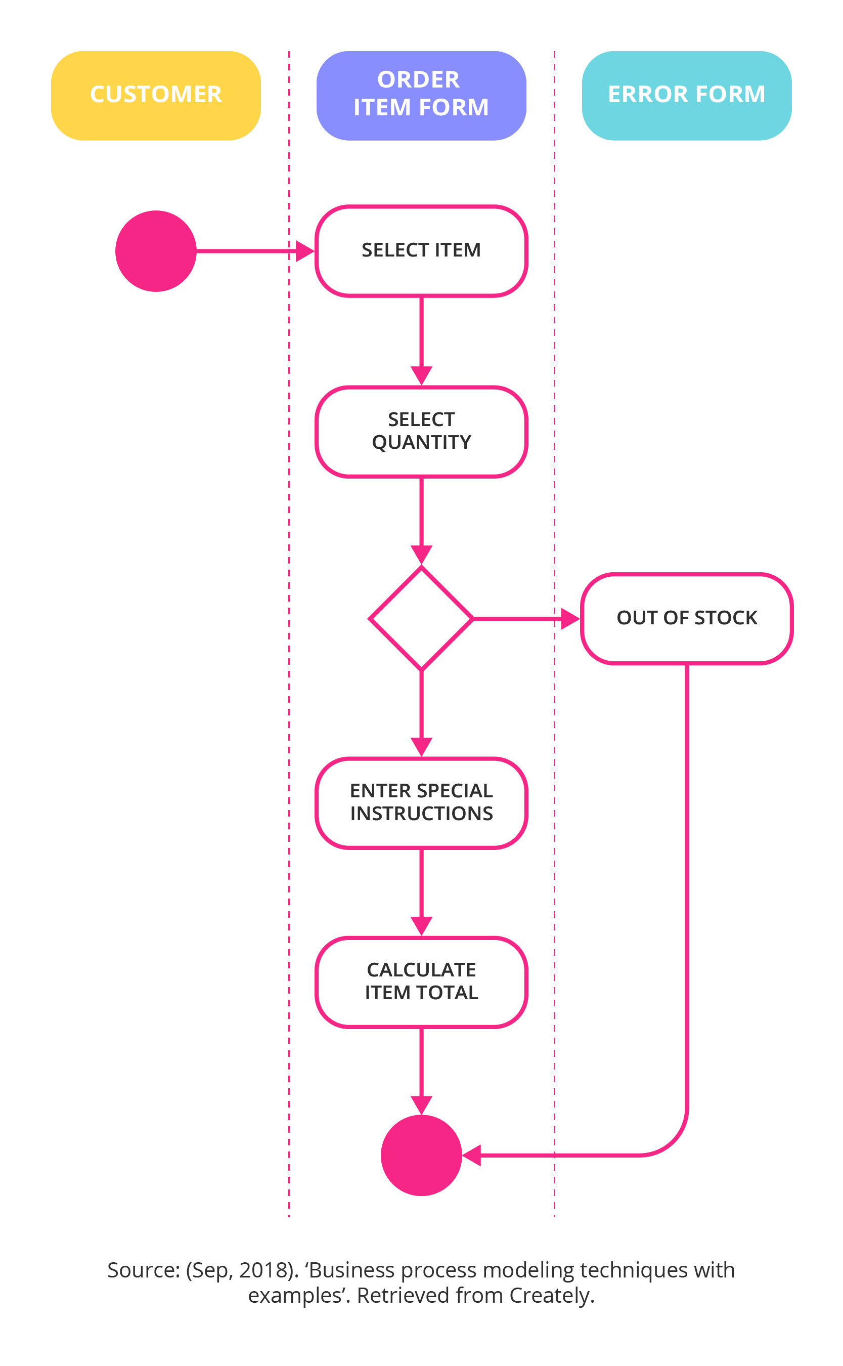
Business process modelling notation (BPMN) is comprised of symbols that are used as a representation of tasks and workflows. Any symbols can be used in your business process, but using standardised ones allows you to collaborate with outside analysts more easily, and it spares you from having to invent your own visual language.
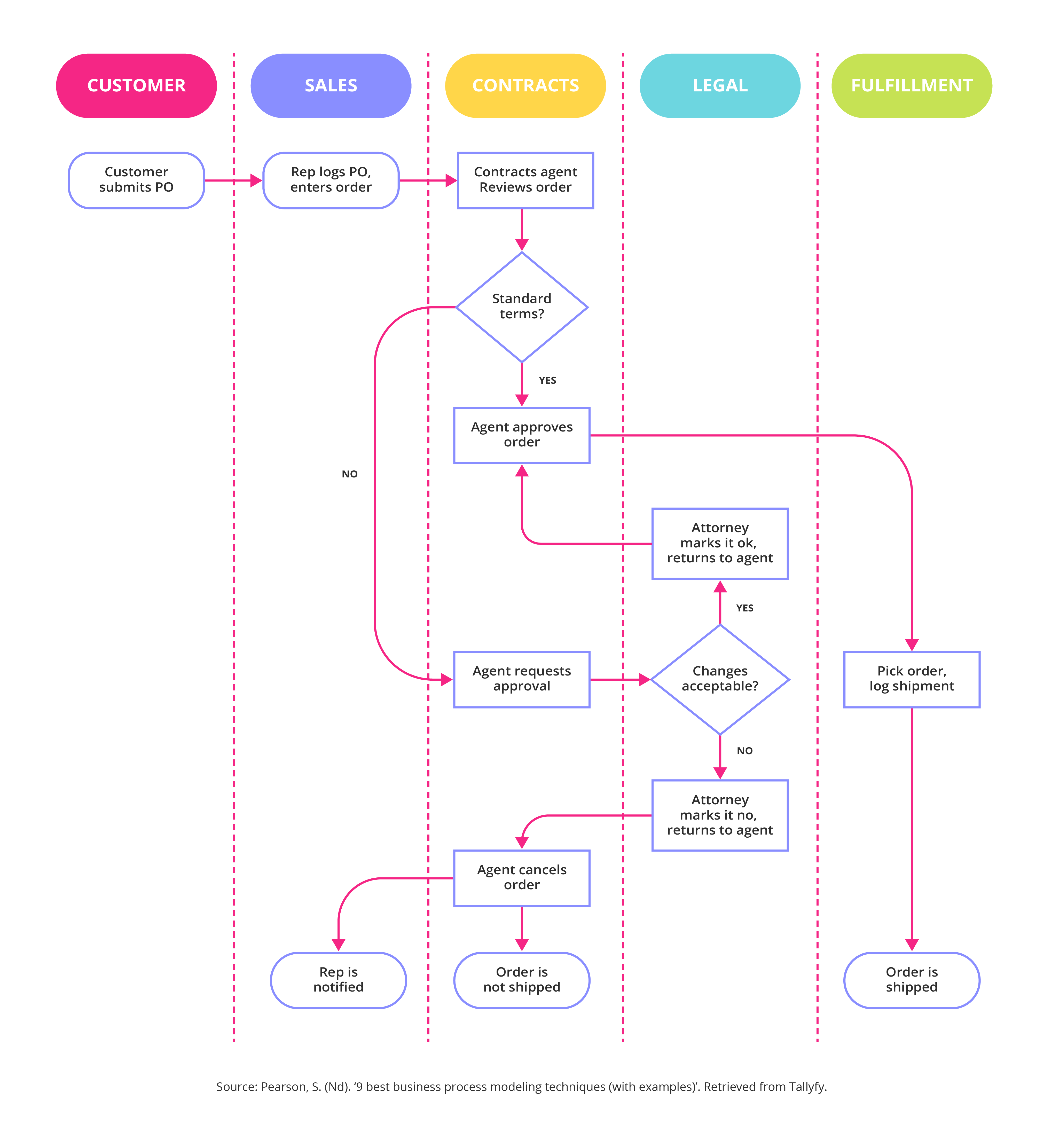
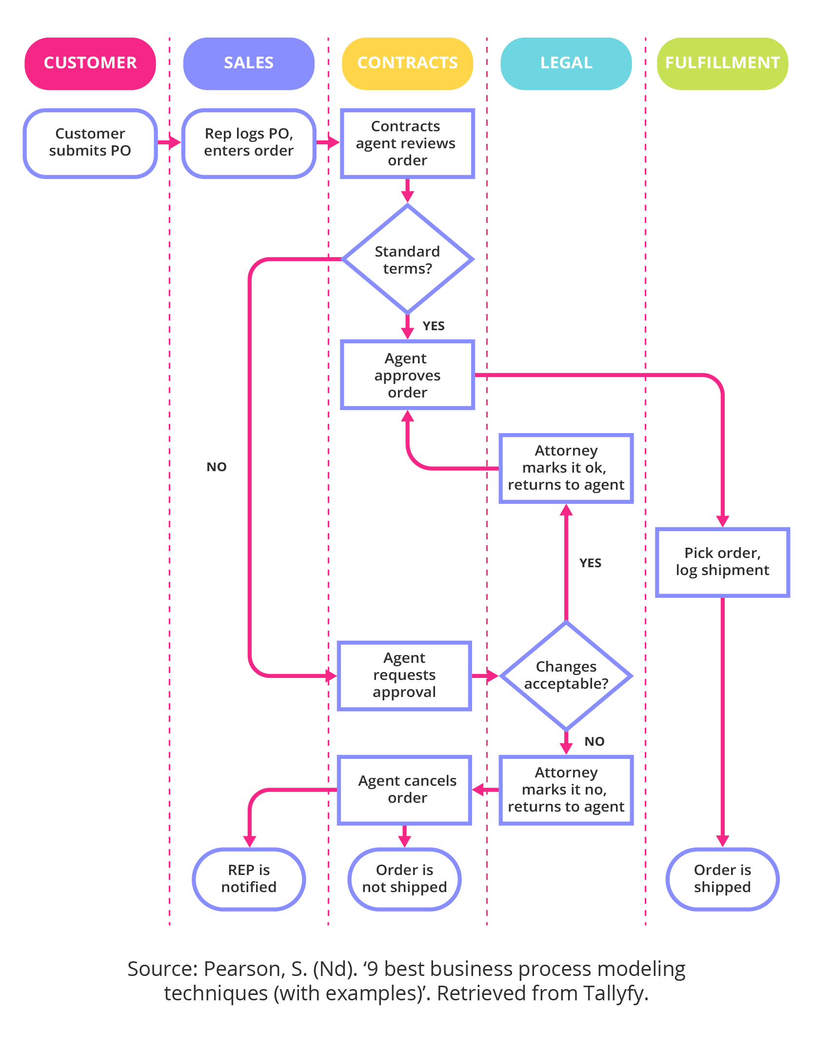
BPMN symbols fall into the following categories:
- Flow objects. Shows the flow of the process and are represented as follows:
- Circles. Events are displayed inside of circular shapes
- Rectangles. Activities fit into rectangular boxes
- Diamonds. Control points or gateways are represented as diamond shapes
- Connecting objects. Used to show how tasks are connected, and in what sequence they occur
- Solid lines. Shows task transfers
- Dashed lines. Shows messages
- Swim lanes. These make provision for subprocesses that share responsibilities and how they interact. The swimlanes are the people or departments that the subprocess impacts on
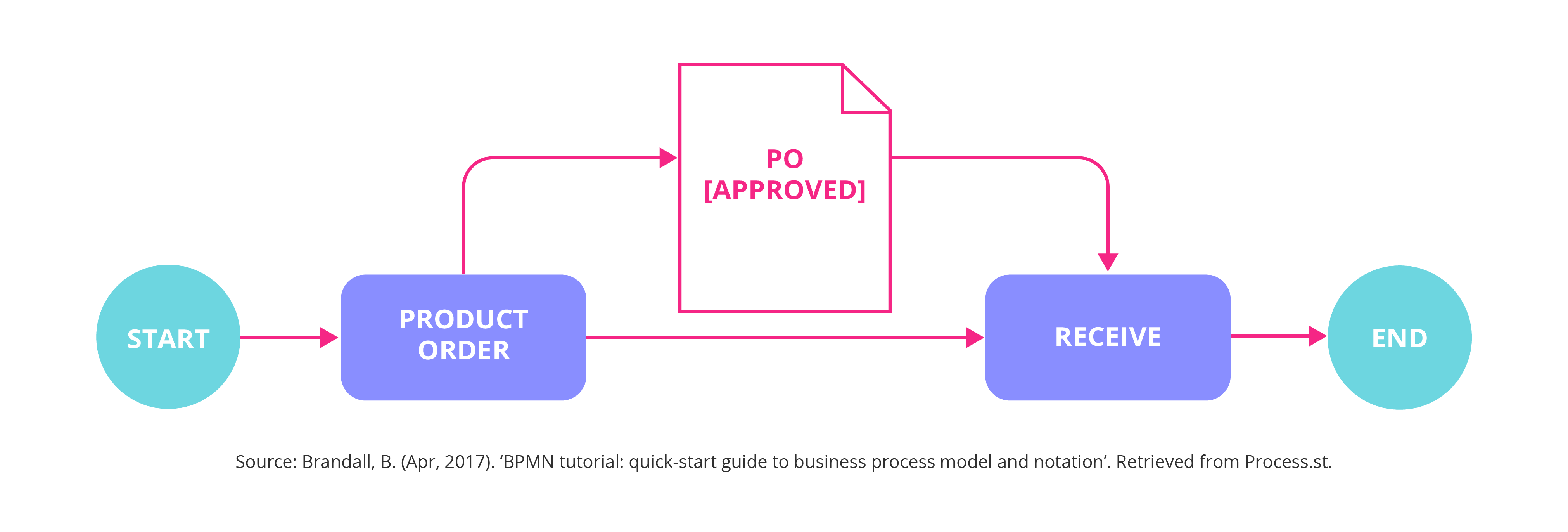
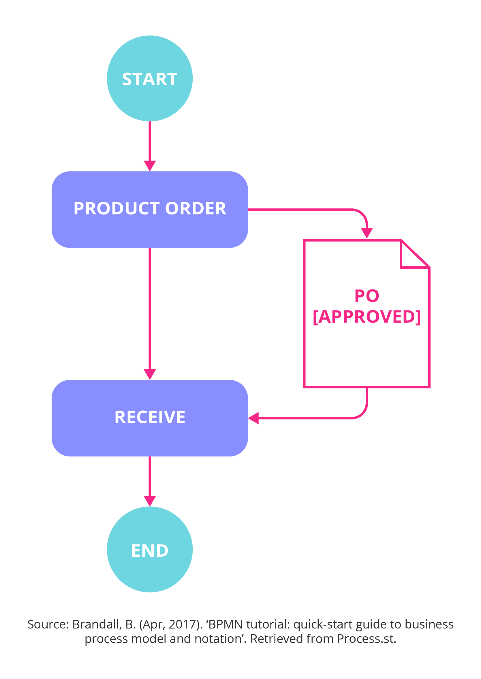
- Artifacts. Used if you have additional information that isn’t a sequence flow or message flow, but that will further explain the process
- Dotted lines. These point to the flow object that the extra information expands on
- Squares outlined with dots and dashes. These group related elements in the diagram
- Square bracket. Text annotations are added here
2. Unified modelling language diagrams
Unified modelling language (UML) is a more modern approach to modelling and documenting processes. UML was initially developed by software developers, but has been successfully used in business process modelling, with a more object-oriented approach to its 14 UML diagram types.
3. Flow chart technique
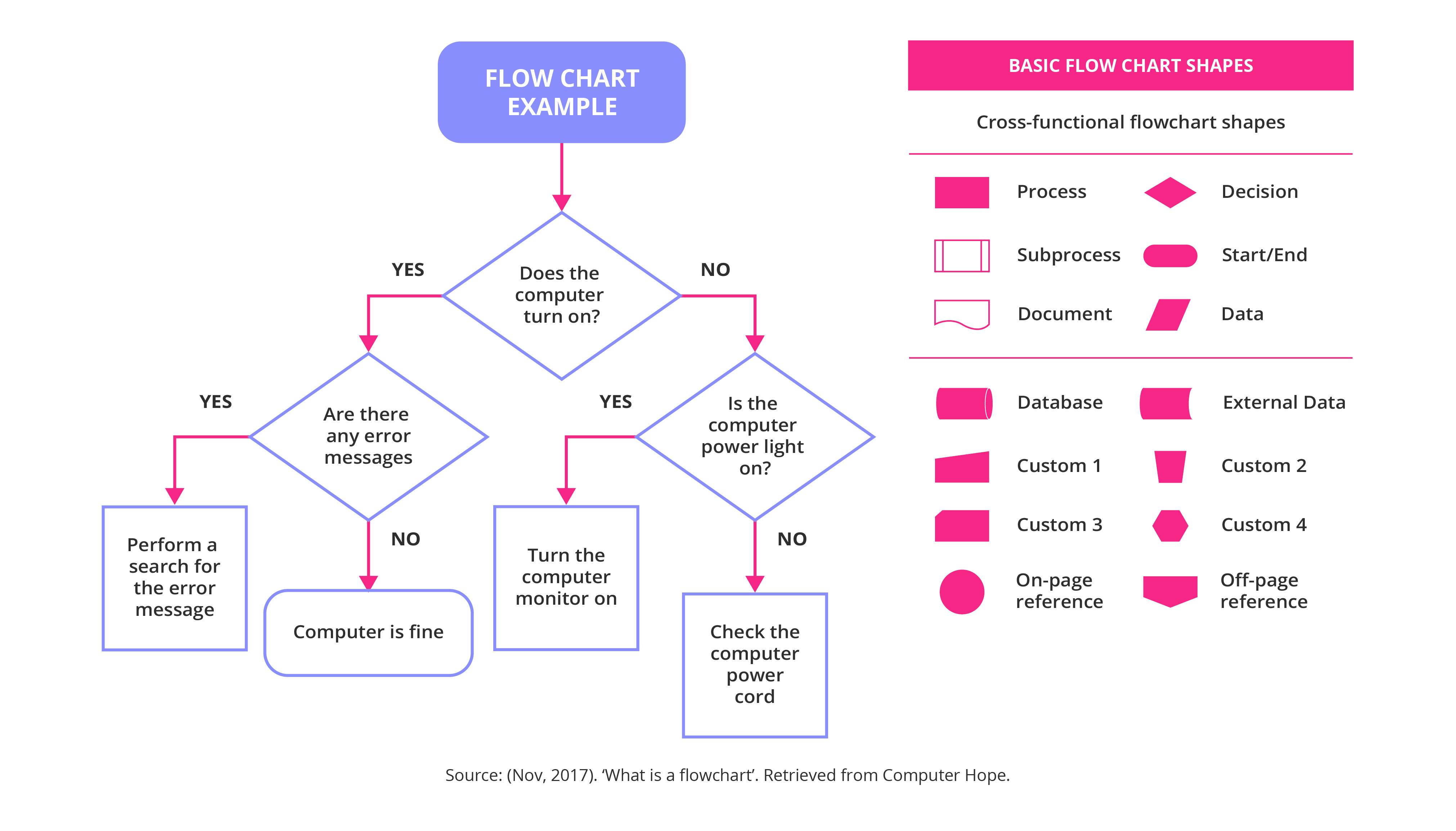
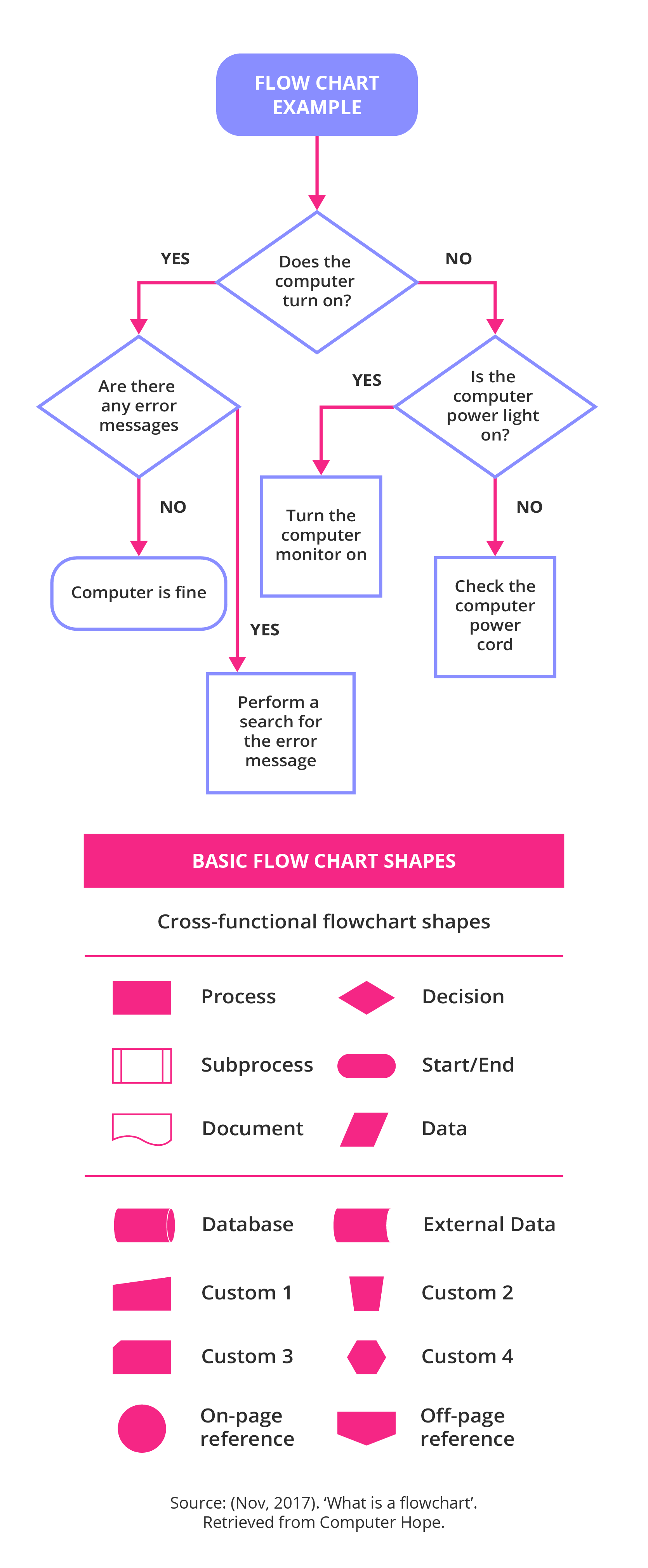
This is a graphic representation of something that is manufactured or produced, which gives people involved in the project or process a single reference point. Flow charts use basic shapes and arrows to define relationships, such as processes, decisions, or data.
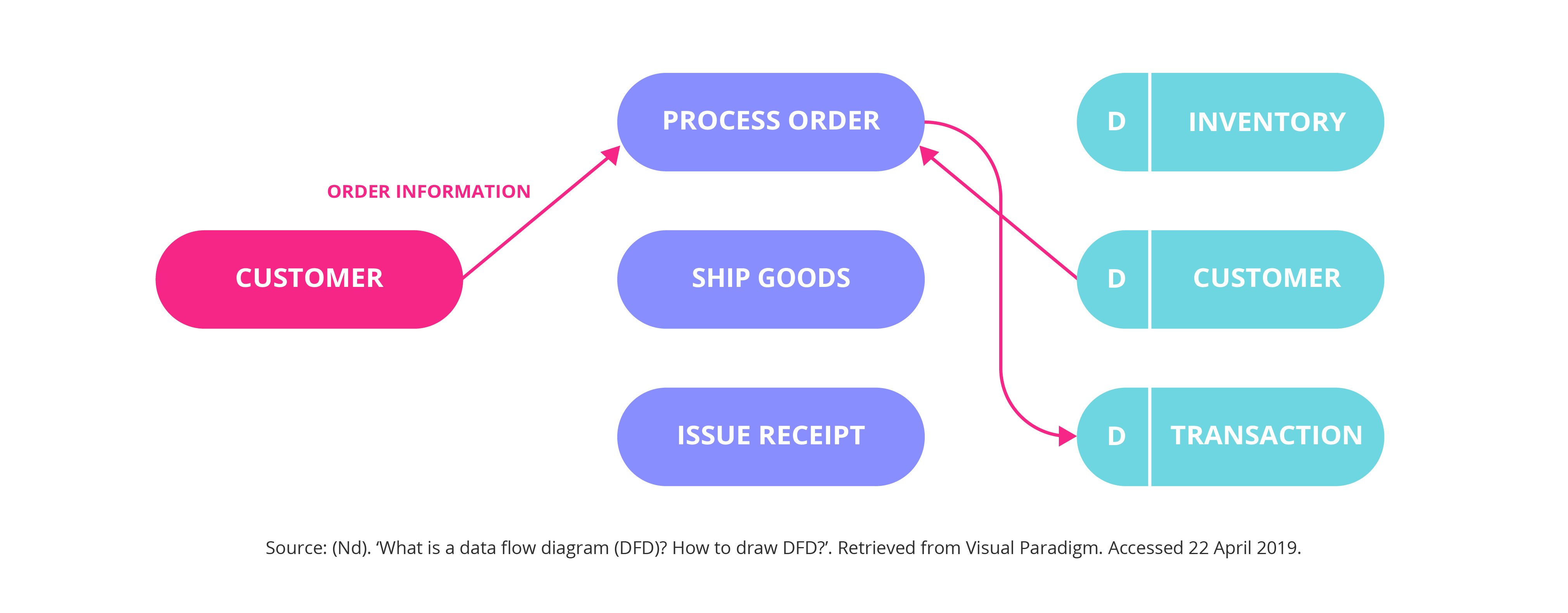
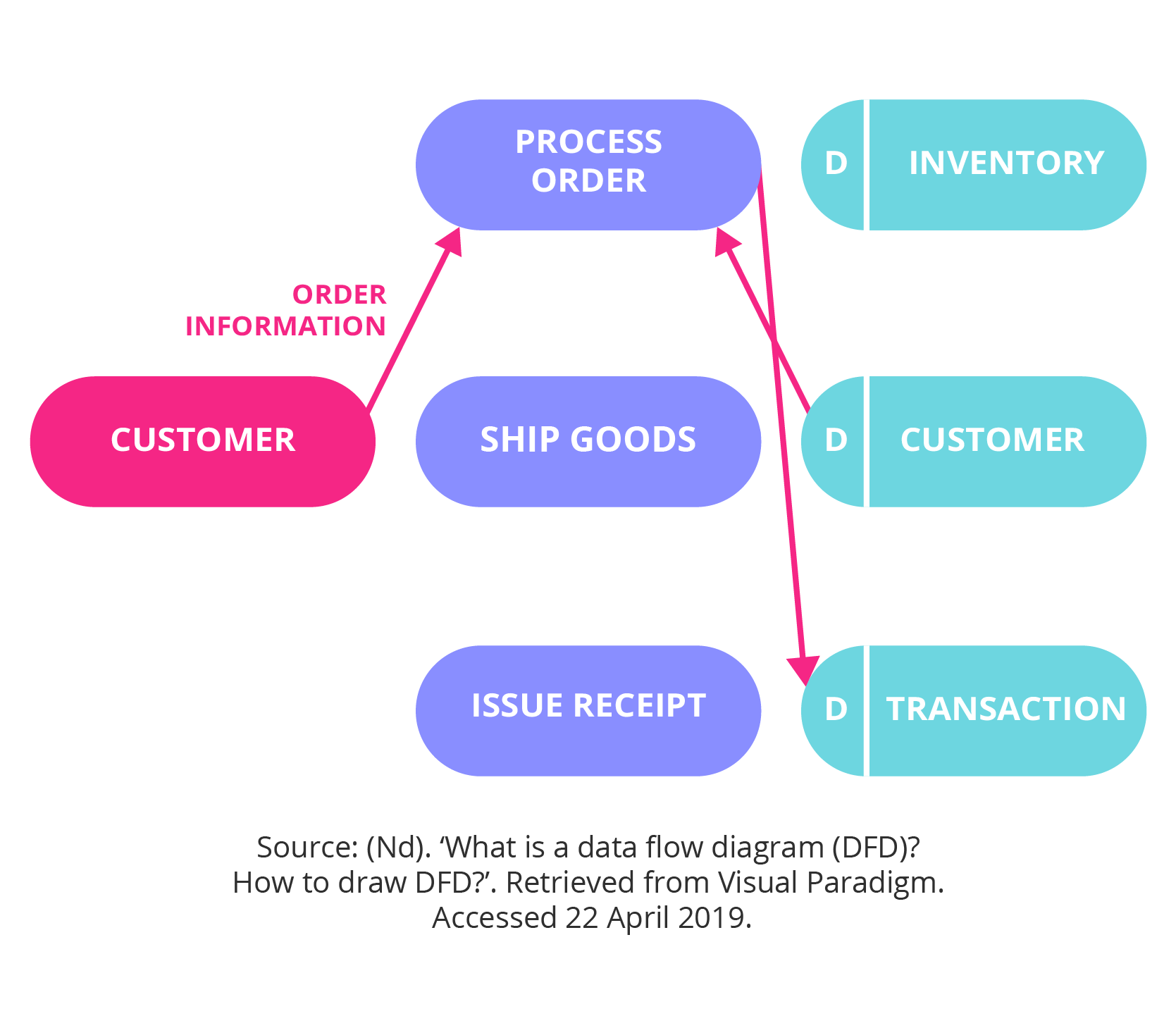
4. Data flow diagrams
Data flow diagrams (DFDs) show how data enters a system from external sources, how data moves internally within the system, and how the data is stored. DFD symbols vary slightly, but are mostly based on the same principles:
- Squares. These show external entities, which are either the source of data, or the destination
- Rounded rectangles. These represent processes that receive data as input, interact with it, and then produce an output
- Arrows. These show the flow of data, either as electronic data or physical items
- Open-ended rectangles. This represents data stores, and include electronic stores like databases or XML files, as well as physical stores, such as or filing cabinets or stacks of paper
5. Role activity diagrams
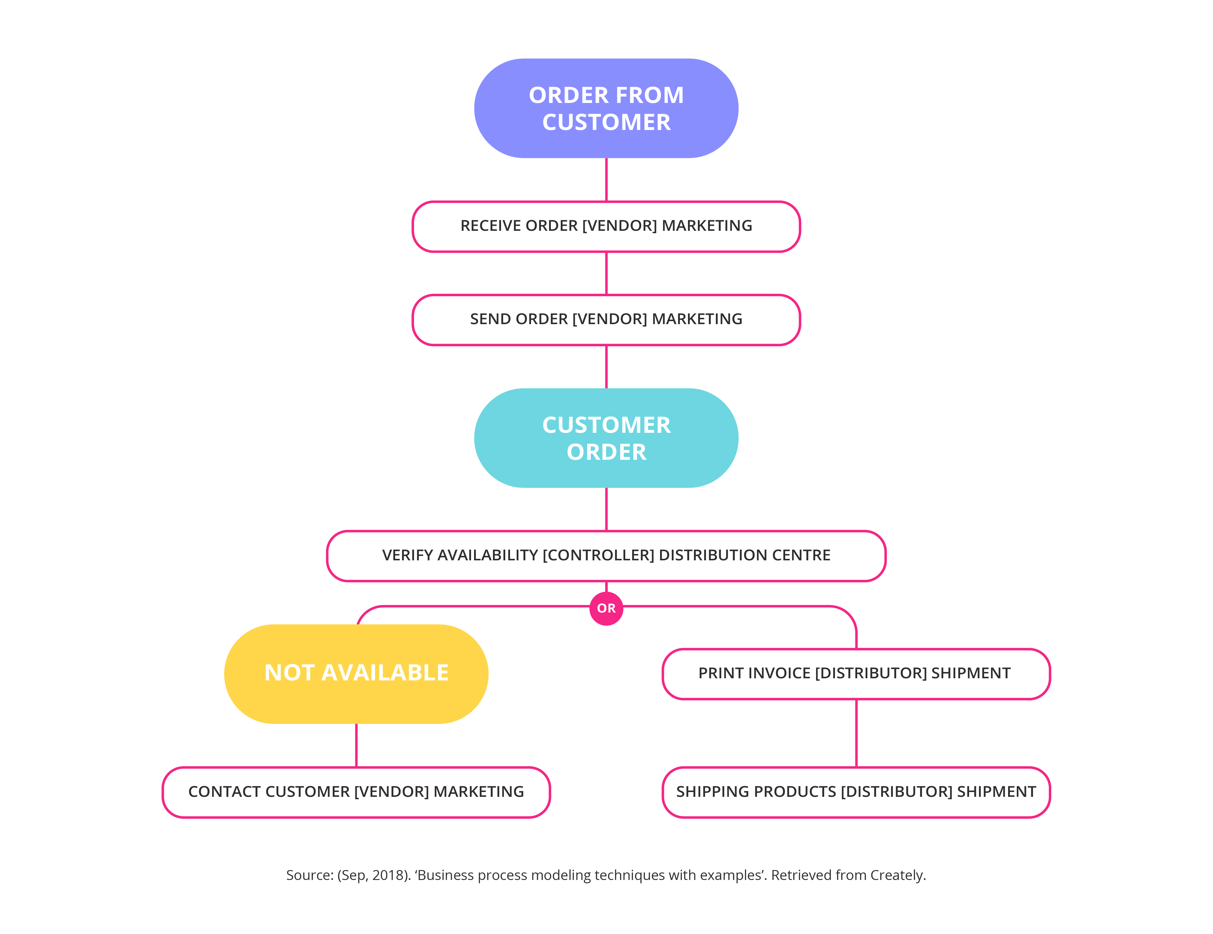
Role activity diagrams (RADs) are used to map out the intangible roles or ideas of behaviour that are desired within the company. These can often be functions within the business, systems in IT, or customer and supplier roles. RADs are easy to read and understand, and often provide a different perspective on a process, which helps support communication.
6. Role interaction diagrams
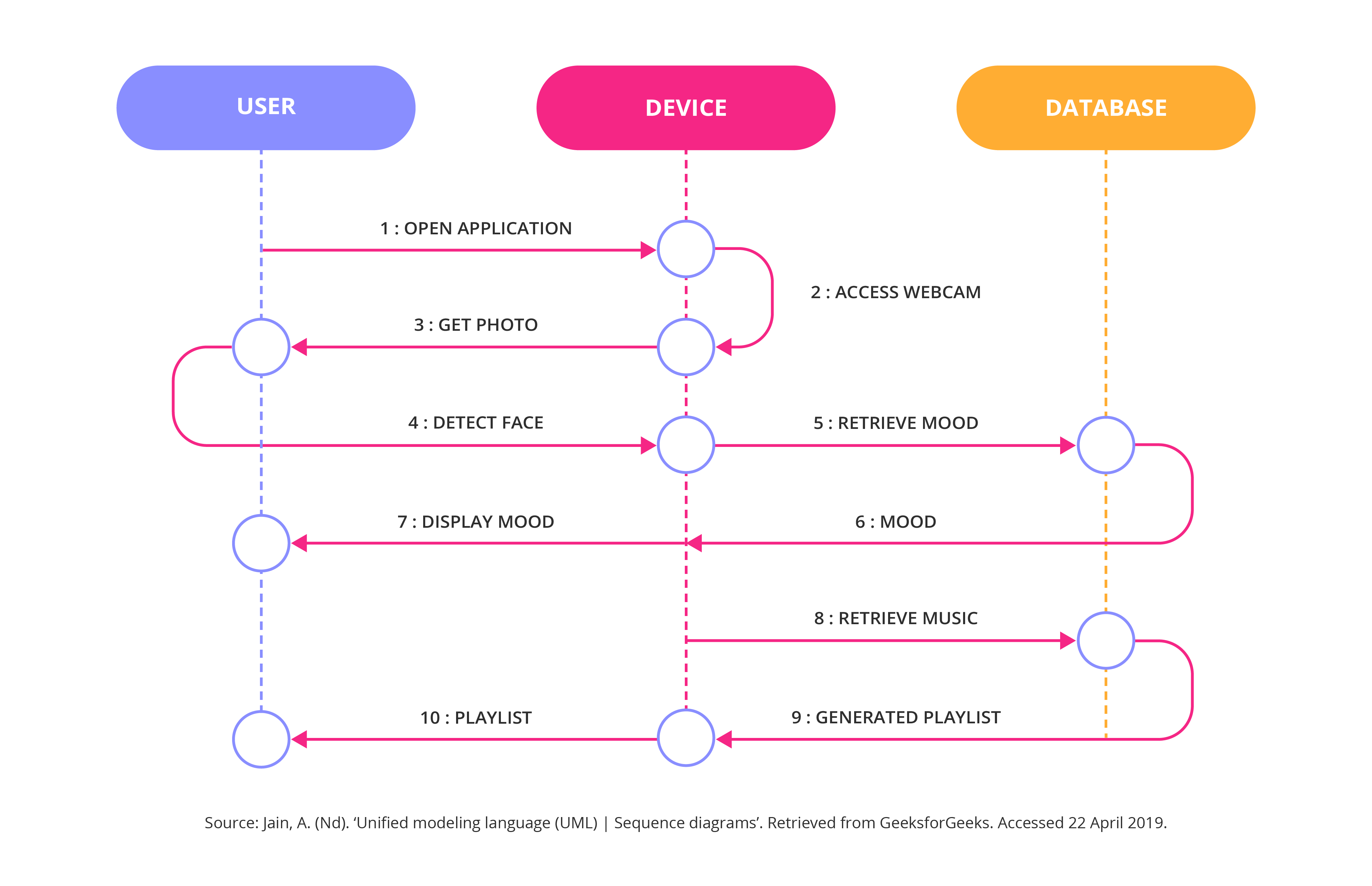
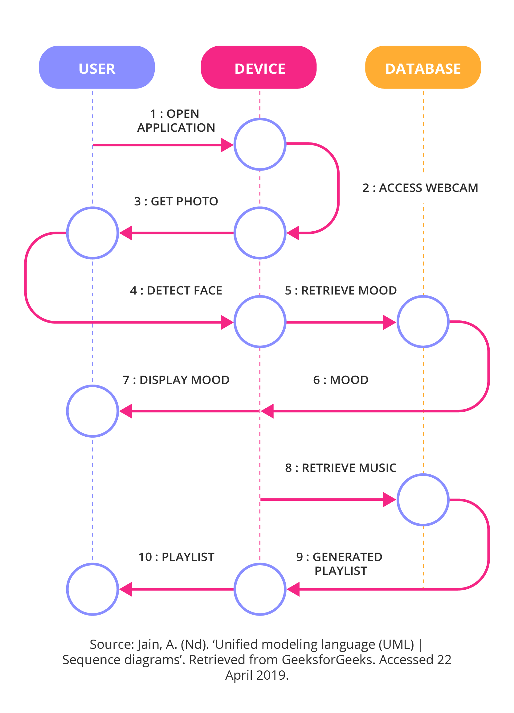
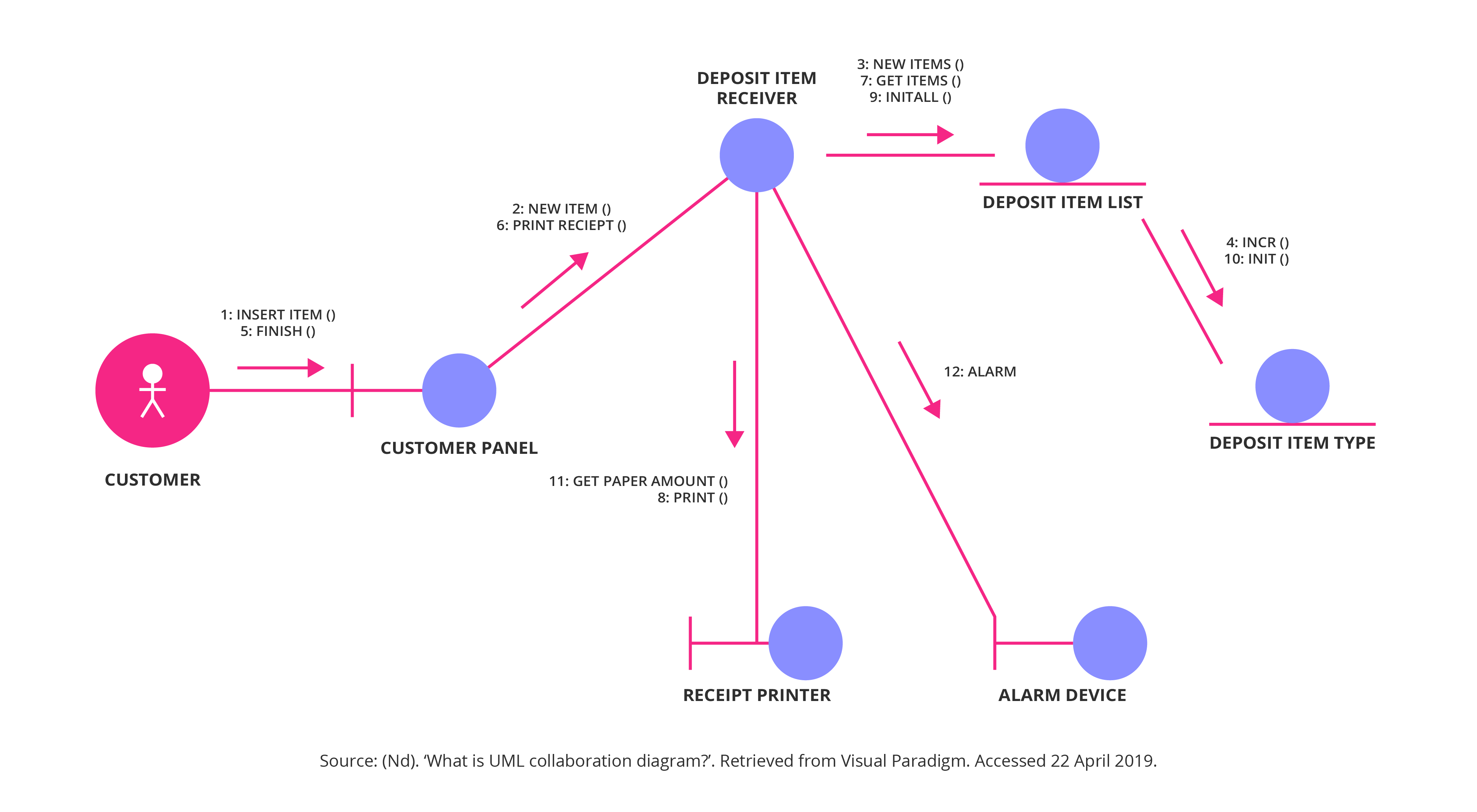
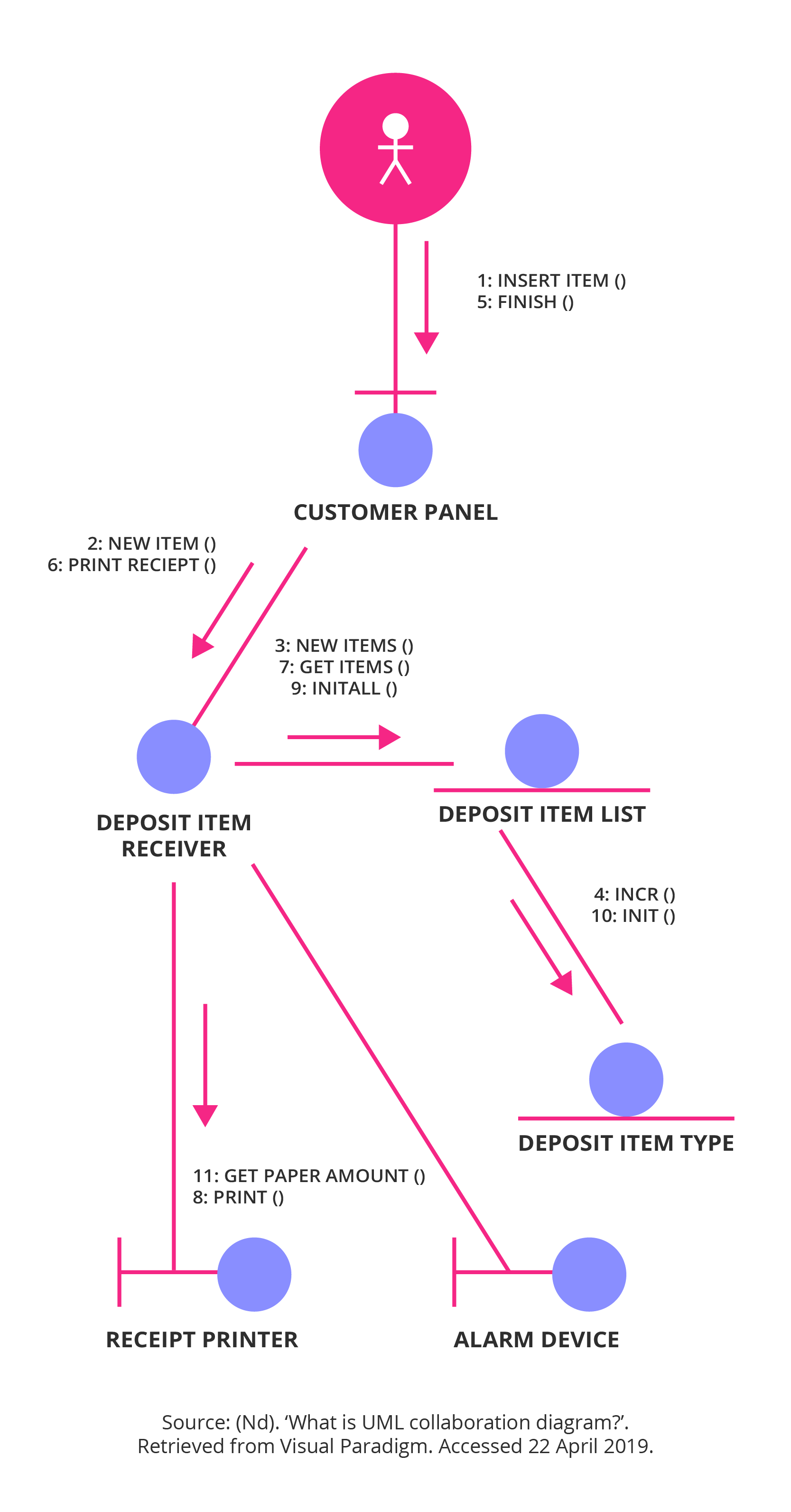
Interaction diagrams are business process models that graphically illustrate the interaction of various processes with each other within a system. Interaction diagrams come in two forms: sequence diagrams and collaboration diagrams. There are two types of interaction diagrams typically used to capture the various aspects of interaction in a system:
- Sequence diagrams. A sequence diagram shows the interaction between objects in the sequence in which they take place. Sequence diagrams describe how the objects function within a system, and in what order, and are often used to document and understand what is required for new and existing systems
- Collaboration diagram.15 Collaboration diagrams are used to define and clarify the roles of the objects that carry out a certain flow of events in a visual format, and serve as the main source of information when determining class responsibilities and interfaces
7. Gantt charts
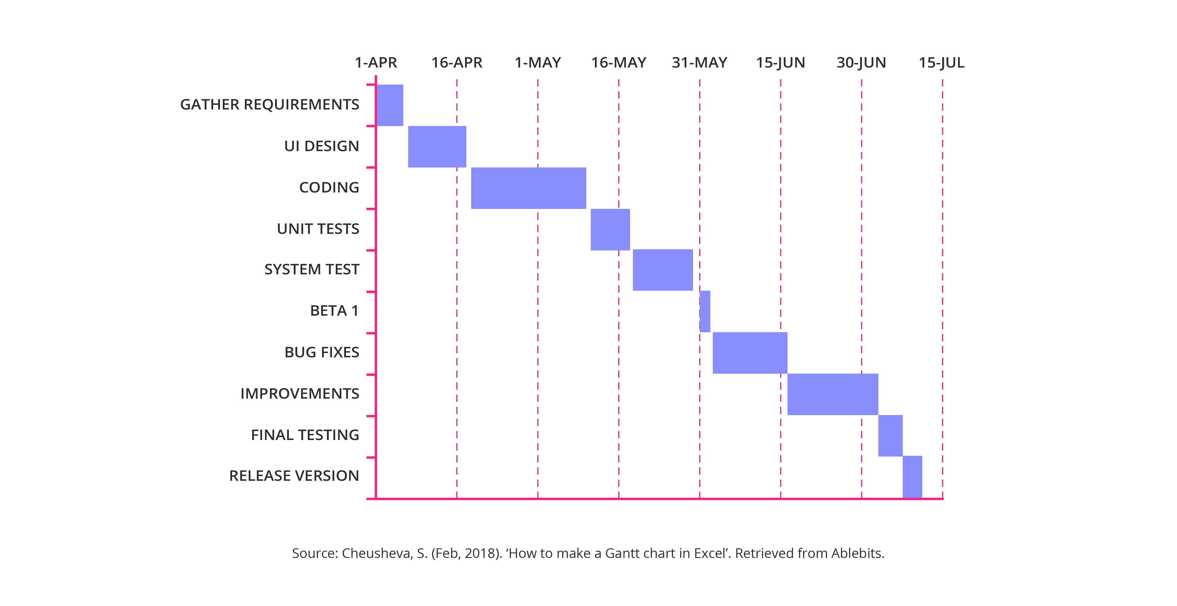
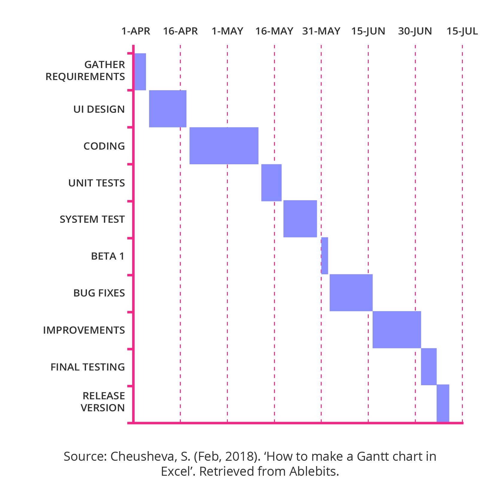
In the late 19th century, Gantt charts were the gold standard, and are often the go-to business process model for companies preparing for projects with distinct timelines, or that have time-sensitive processes that need to be captured and tracked. Gantt charts make it easy for people involved in different parts of a process to see when they are meant to start work, and by when each task should be complete, and to check whether all the subprocesses are on schedule.
8. Integrated definition for function modelling
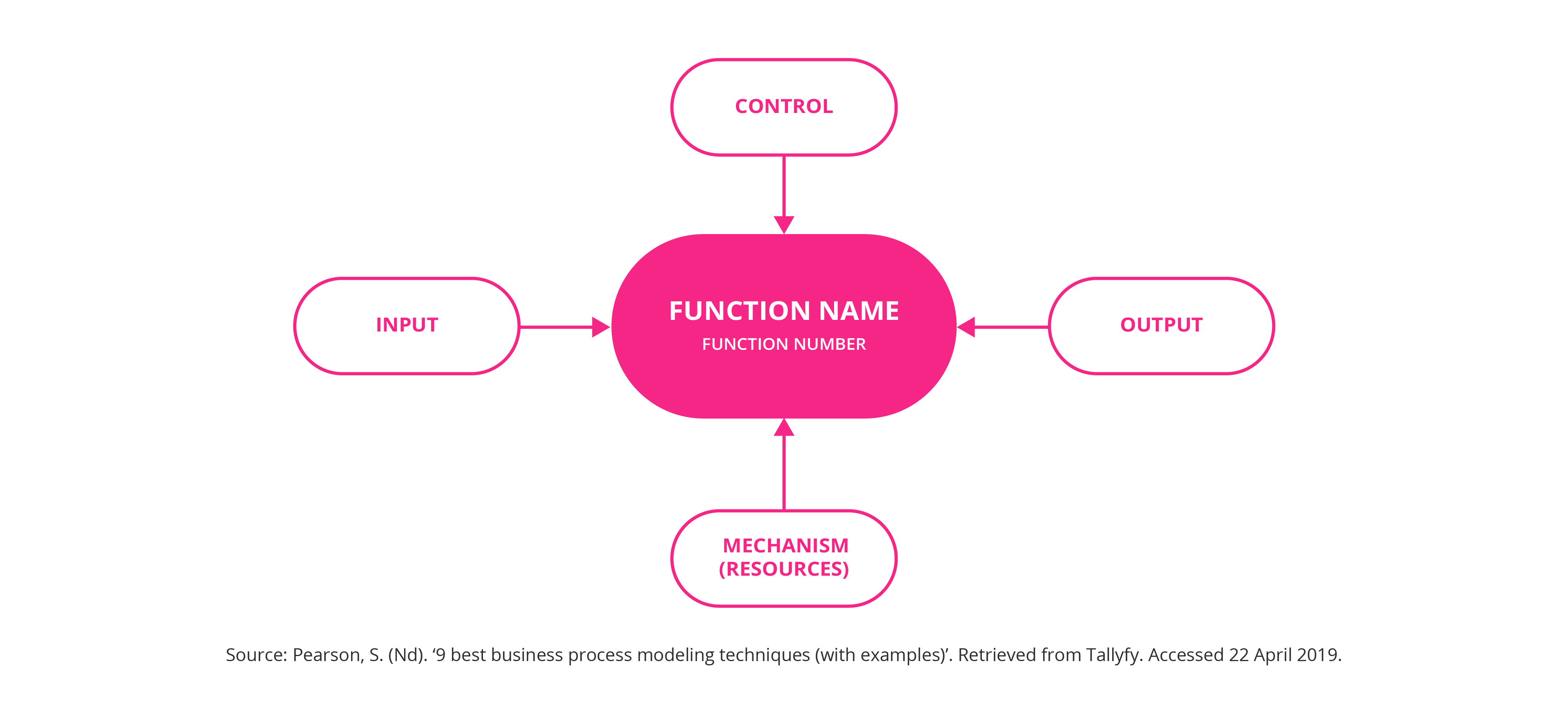
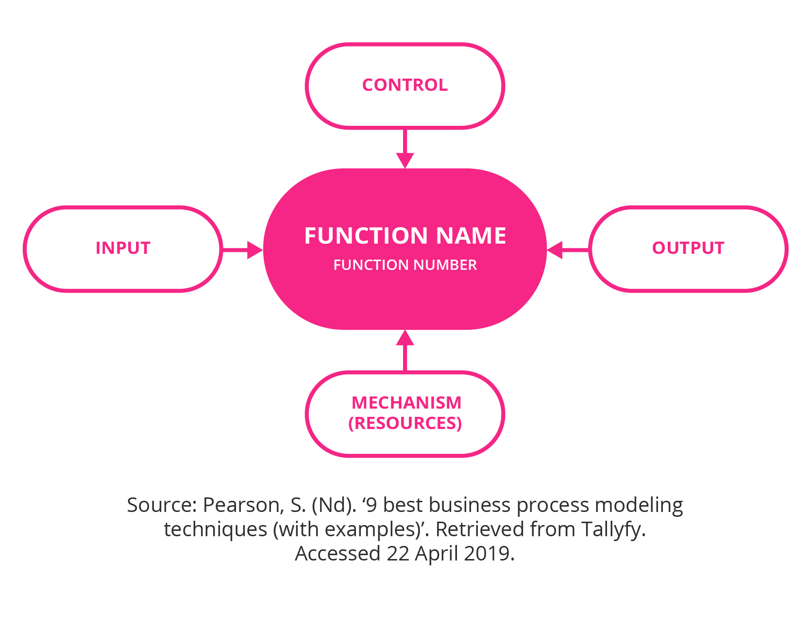
Integrated definition (IDEF) for function modelling displays when parent activities give rise to child diagrams. There are 15 forms of IDEF and each addresses a different type of flow for functions, information, data, simulation model design, process description capture, and so on.
9. Coloured Petri nets
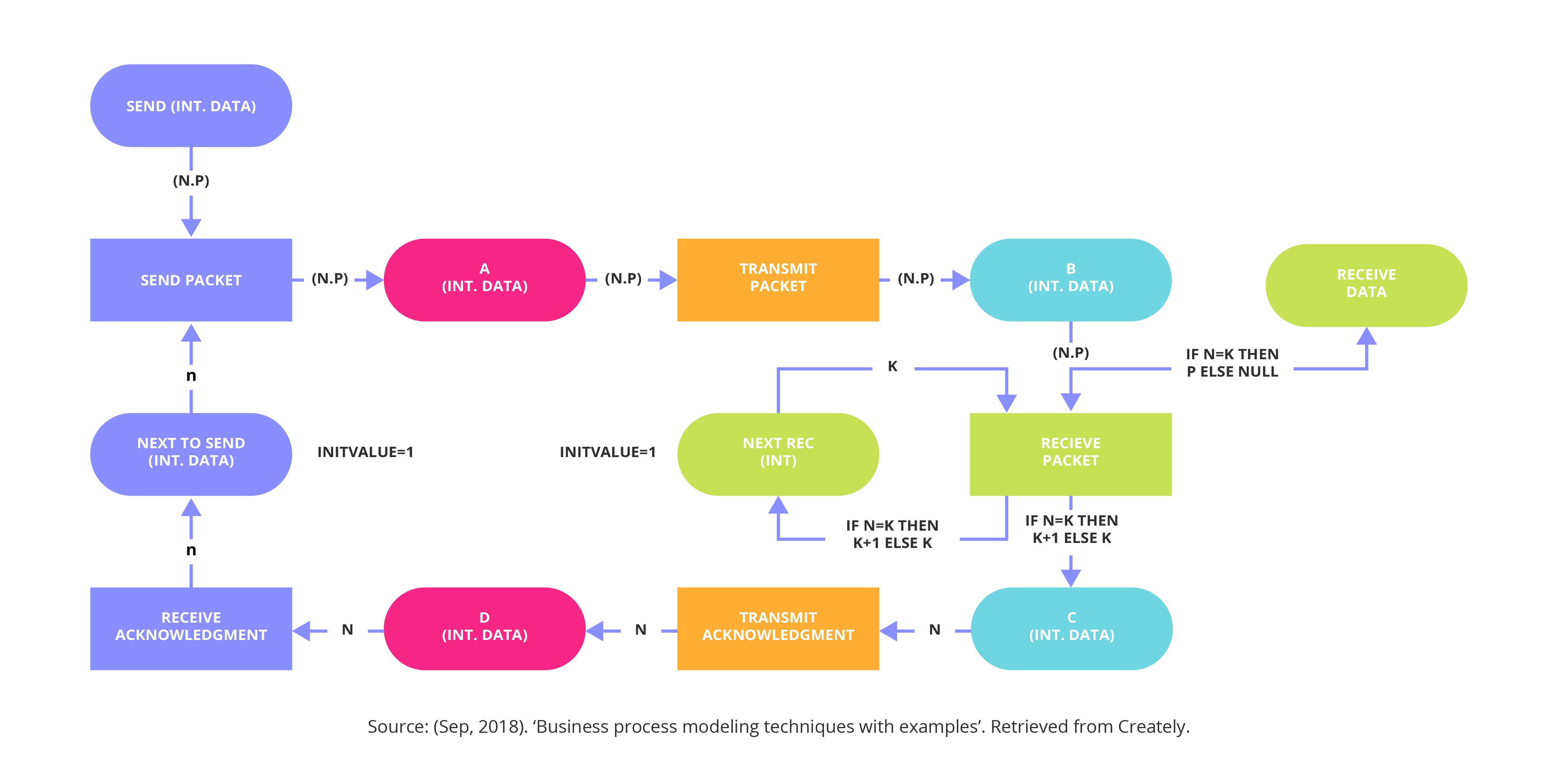
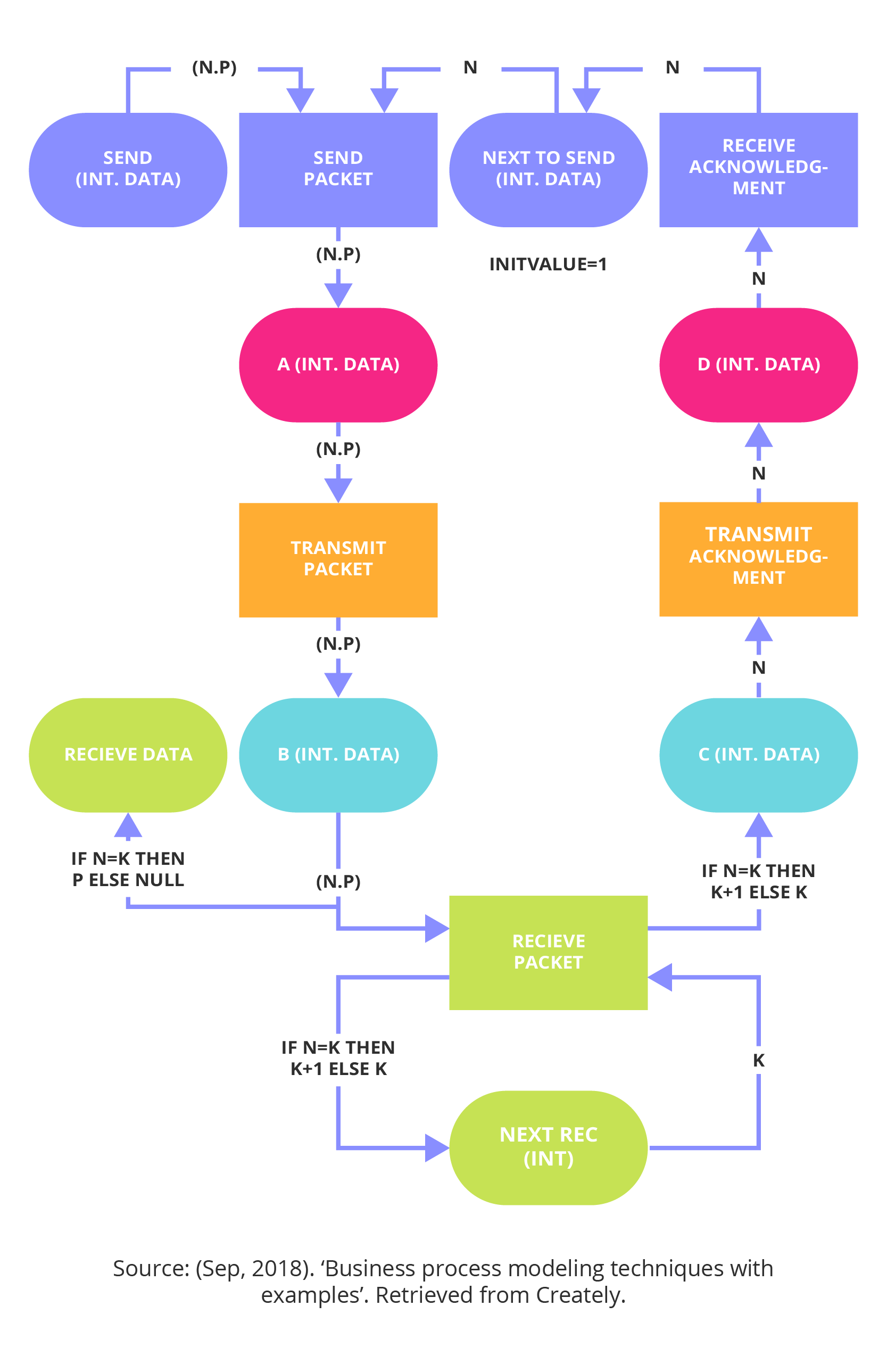
When a system has numerous processes that interact and synchronise with each other, then coloured Petri nets are ideal. This modelling technique is used to design, specify, simulate and verify systems.
Petri nets are unique in that they can represent both a state – such as passive, unsent, or waiting – and an action – such as send, receive, or transmit – in the same diagram. Coloured nets use colours to differentiate their symbols, and use a formal, mathematical representation with well-defined syntax and semantics.
10. Object oriented methods
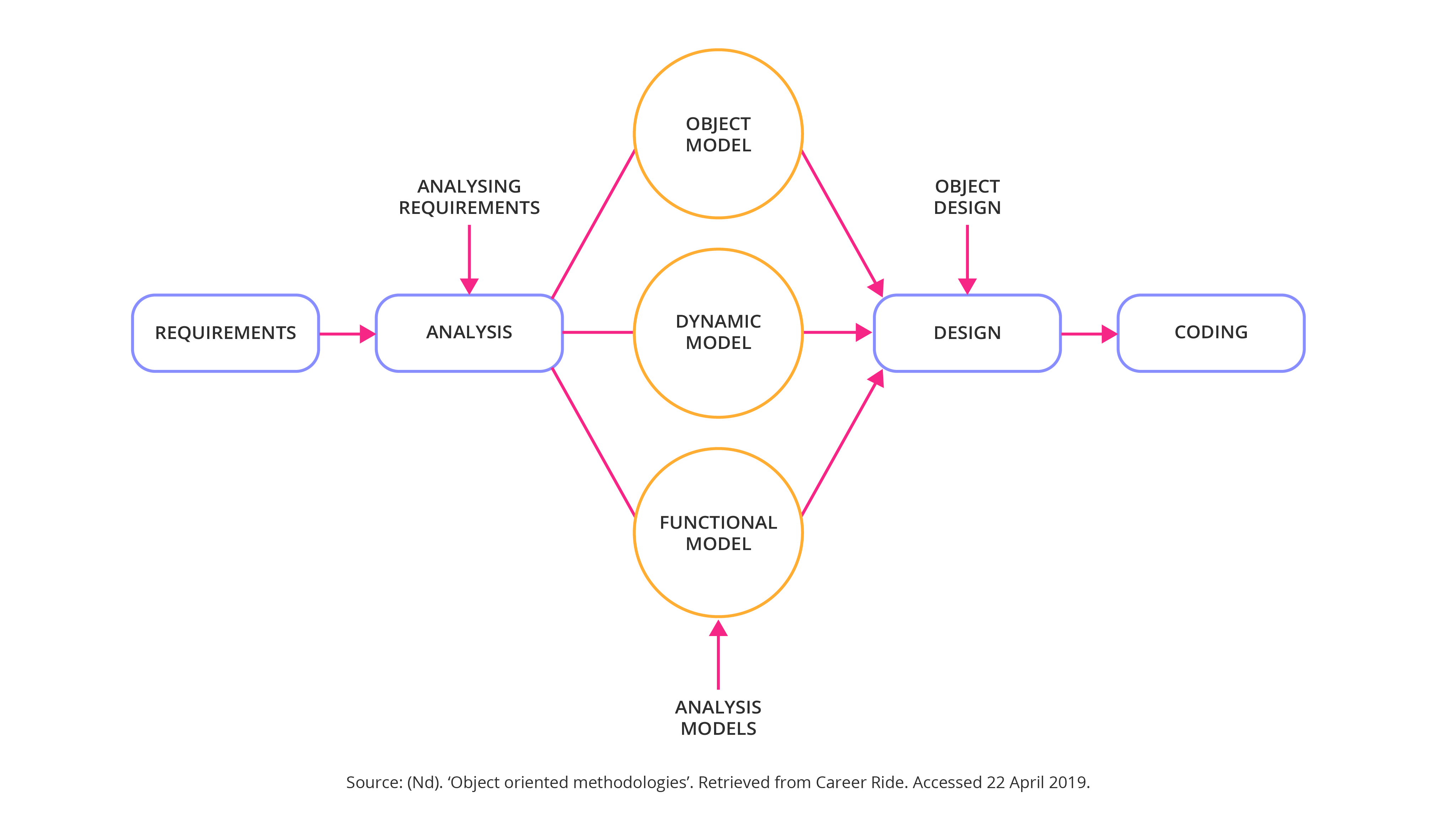
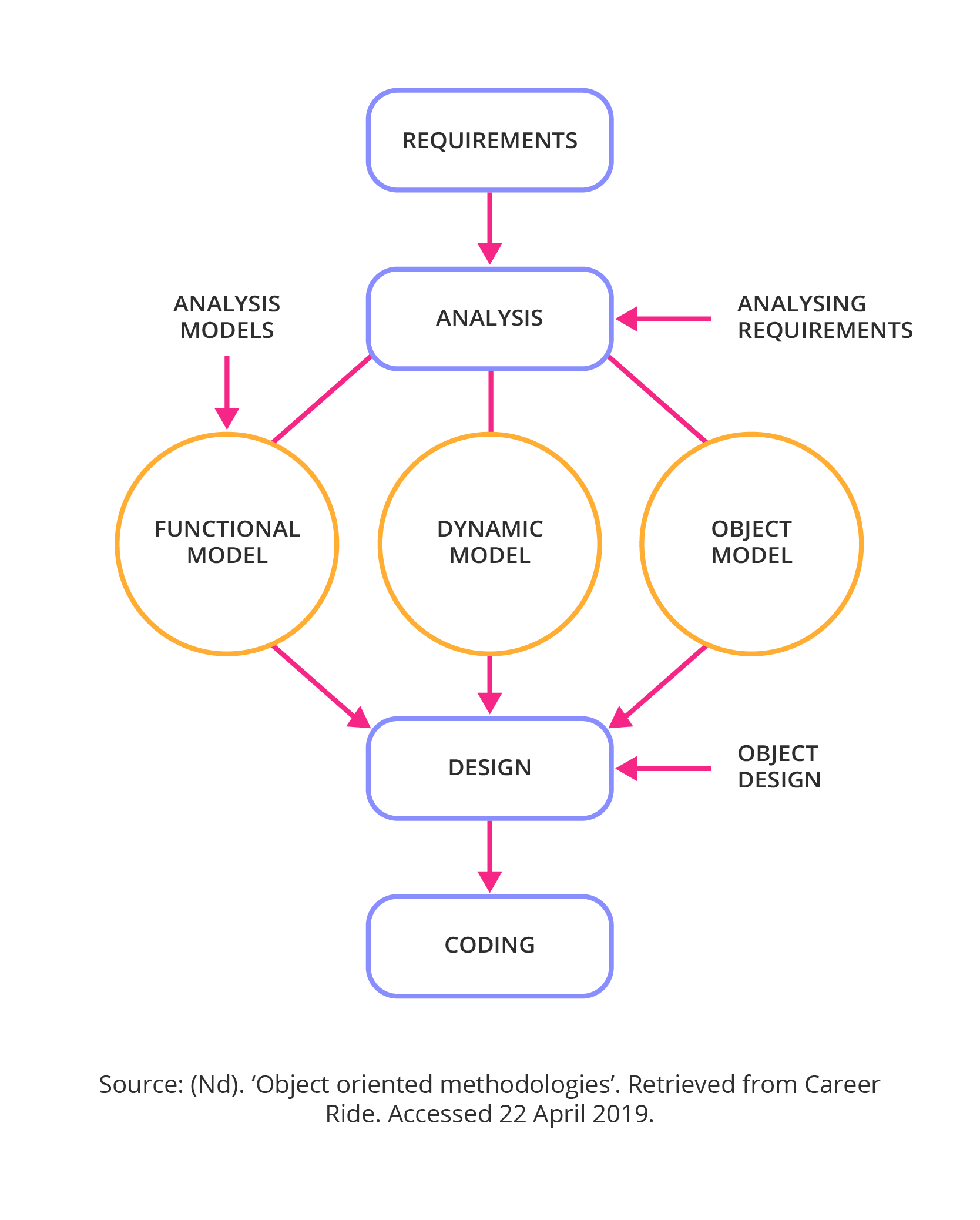
The object oriented method of business process modelling is more than just modelling with objects: it encompasses message-passing, encapsulation (where internal detail is hidden), inheritance from class to subclass, and polymorphism (where the same procedure can operate on different data types).
Which business process modelling technique will you select for your business? Find the one that will ensure those involved in the system or process carry out their tasks in a consistent and efficient way, producing a predictable, measurable outcome.
Think more strategically about your business process designs
Register now and join MIT Sloan online
- 1 (Nd). ‘The why and how of business modelling’. Retrieved from KissFlow. Accessed 22 April 2019.
- 2 Proctor, J. (2018). ‘10 perilous misconceptions of censuring current stat mapping & analysis’. Retrieved from Inteq Group.
- 3 (Nd). ‘What is BPM?’. Retrieved from Workflow Management Coalition. Accessed 22 April 2019.
- 4 (Nd). ‘The why and how of business modelling’. Retrieved from KissFlow. Accessed 22 April 2019.
- 5 Pearson, S. (Nd). ‘9 best business process modeling techniques (with examples)’. Retrieved from Tallyfy.
- 6 Pearson, S. (Nd). ‘9 best business process modeling techniques (with examples)’. Retrieved from Tallyfy.
- 7 Ceta, N. (Nd). ‘All you need to know about UML diagrams: types and 5+ examples’. Retrieved from Tallyfy.
- 8 Pearson, S. (Nd). ‘9 best business process modeling techniques (with examples)’. Retrieved from Tallyfy.
- 9 Rouse, M. (Aug, 2008). ‘Flowchart’. Retrieved from TechTarget.
- 10 Ambler, S. (Nd). ‘Data flow diagram (DFDs): an agile introduction’. Retrieved from Agile Modeling.
- 11 Bangerter, J. (Jul, 2017). ‘Data flow diagram symbols, types, and tips’. Retrieved from LucidChart.
- 12 (Sep, 2018). ‘Business process modeling techniques with examples’. Retrieved from Creately.
- 13 Jain, A. (Nd). ‘Unified modeling language (UML) | Sequence diagrams’. Retrieved from GeeksforGeeks. Accessed 22 April 2019.
- 14 Jain, A. (Nd). ‘Unified modeling language (UML) | Sequence diagrams’. Retrieved from GeeksforGeeks. Accessed 22 April 2019.
- 15 (Nd). ‘What is UML collaboration diagram?’. Retrieved from Visual Paradigm. Accessed 25 April 2019.
- 16 (Sep, 2018). ‘Business process modeling techniques with examples’. Retrieved from Creately.
- 17 Pearson, S. (Nd). ‘9 best business process modeling techniques (with examples)’. Retrieved from Tallyfy. Accessed 25 April 2019.
- 18 (Sep, 2018). ‘Business process modeling techniques with examples’. Retrieved from Creately.
- 19 Jensen, K. (Jun, 2005). ‘An introduction to the theoretical aspects of colored Petri nets’. Retrieved from Springer Link.
- 20 (Sep, 2018). ‘Business process modeling techniques with examples’. Retrieved from Creately.
- 21 (Nd). ‘Object oriented methodologies’. Retrieved from Career Ride.


![Toni Kroos là ai? [ sự thật về tiểu sử đầy đủ Toni Kroos ]](https://evbn.org/wp-content/uploads/New-Project-6635-1671934592.jpg)


