
How do electricity transformers work?


Advertisement
Mục Lục
How does a transformer work?
A transformer is based on a very simple fact about electricity: when
a fluctuating electric current flows through a wire, it generates a magnetic
field (an invisible pattern of magnetism) or “magnetic flux” all
around it. The strength of the magnetism (which has the rather
technical name of magnetic flux density) is
directly related to
the size of the electric current. So the bigger the current, the
stronger the magnetic field. Now there’s another interesting fact about
electricity too. When a magnetic field fluctuates around a piece of
wire, it generates an electric current in the wire. So if we put a
second coil of wire next to the first one, and send a fluctuating
electric current into the first coil, we will create an electric
current in the second wire.
The current in the first coil is usually
called the primary current and the current
in the second wire
is (surprise, surprise) the secondary current.
What we’ve done
here is pass an electric current through empty space from one coil of
wire to another. This is called electromagnetic
induction because the current in the first coil
causes (or “induces”) a current in the second coil.
We can make electrical energy pass more efficiently from one coil to
the other by wrapping them around a soft iron bar (sometimes called a core):

To make a coil of wire, we simply curl the wire round into loops or
(“turns” as physicists like to call them). If
the second coil
has the same number of turns as the first coil, the electric current in
the second coil will be virtually the same size as the one in the first
coil. But (and here’s the clever part) if we have more or fewer turns
in the second coil, we can make the secondary current and voltage
bigger or smaller than the primary current and voltage.
One important thing to note is that this trick works only if the
electric current is fluctuating in some way. In other words, you have
to use a type of constantly reversing electricity called alternating
current (AC) with a transformer. Transformers do not work with direct current (DC), where a steady current constantly flows in the same
direction.
Step-down transformers
If the first coil has more turns that the second coil, the secondary
voltage is smaller than the
primary voltage:
This is called a step-down
transformer. If the second coil has half
as many turns as the first coil, the secondary voltage will be half the
size of the primary voltage; if the second coil has one tenth as many
turns, it has one tenth the voltage. In general:
Secondary voltage ÷
Primary voltage = Number of turns in secondary ÷ Number of turns
in primary
The current is transformed the opposite way—increased in size—in a
step-down transformer:
Secondary current ÷ Primary current = Number of turns in
primary ÷ Number of turns in secondary
So a step-down transformer with 100 coils in the primary and 10
coils in the secondary will reduce the voltage by a factor of 10 but
multiply the current by a factor of 10 at the same time. The power in
an electric current is equal to the current times the voltage (watts =
volts x amps is one way to remember this), so you can see the power in
the secondary coil is theoretically the same as the power in the
primary coil. (In reality, there is some loss of power between the
primary and the secondary because some of the “magnetic flux” leaks out
of the core, some energy is lost because the core heats up, and so on.)
Step-up transformers
Reversing the situation, we can make a step-up
transformer that boosts a
low voltage into a high one:

This time, we have more turns on the secondary
coil than the primary. It’s still true that:
Secondary voltage ÷ Primary voltage = Number of turns in
secondary ÷ Number of turns in primary
and
Secondary current ÷ Primary current = Number of turns in
primary ÷ Number of turns in secondary
In a step-up transformer, we use more turns in the secondary than in
the primary to get a bigger secondary voltage and a smaller secondary
current.
Considering both step-down and step-up transformers, you can see it’s a general rule that
the coil with the most turns has the highest voltage, while the coil with the fewest turns
has the highest current.
Transformers in your home

Photo: Typical home transformers. Anticlockwise
from top left: A modem transformer, the white transformer in an iPod
charger, and a cellphone charger.
As we’ve already seen, there are lots of huge transformers in towns
and cities where the high-voltage electricity from incoming power lines
is converted into lower-voltages. But there are lots of transformers in
your home also. Big electric appliances such as washing machines and dishwashers use relatively high voltages
of 110–240 volts, but electronic devices such as laptop computers and chargers for MP3 players and mobile cellphones use relatively tiny
voltages: a laptop needs about 15 volts, an iPod charger needs 12
volts, and a cellphone typically needs less than 6 volts when you
charge up its battery. So electronic appliances like these have small
transformers built into them (often mounted at the end of the power
lead) to convert the 110–240 volt domestic
supply into a smaller voltage they can use. If you’ve ever wondered why
things like cellphones have those big fat chunky power cords, it’s because
they contain transformers!

Photos: An electric toothbrush standing on its charger. The battery in the brush charges by induction: there is no direct electrical contact between the plastic brush and the plastic charger unit in the base. An induction charger is a special kind of transformer split into two pieces, one in the base and one in the brush. An invisible magnetic field links the two parts of the transformer together.
Induction chargers
Many home transformers (like the ones used by iPods and
cellphones) are designed to charge up rechargeable batteries.
You can see exactly how they work: electricity flows
into the transformer from the electricity outlet on your wall, gets
transformed down to a lower voltage, and flows into the battery in your
iPod or phone. But what happens with something like an electric toothbrush, which has no
power lead? It charges up with a slightly different type of
transformer, which has one of its coils in the base of the brush and
the other in the charger that the brush stands on. You can find out
how transformers like this work in our article about induction chargers.
Transformers in practice

Photo: Blast from the past: A strangely shaped transformer at the Chickamauga Dam near Chattanooga, Tenn.
Photographed in 1942 by Alfred T. Palmer, Office of War Administration, courtesy of US Library of Congress.
If you’ve got some of these transformer chargers at home (normal ones or induction chargers), you’ll have noticed that they get warm after they’ve been on for a while. Because all transformers produce some waste heat, none of them are perfectly efficient: less electrical energy is produced by the secondary coil than we feed into the primary, and the waste heat accounts for most of the difference.
On a small home cellphone charger, the heat loss is fairly minimal (less than that from an old-fashioned, incandescent light bulb) and not usually something to worry about.
But the bigger the transformer, the bigger the current it carries and the more heat it produces. For a substation transformer like the one in our photo up above, which is about as wide as a small car, the waste heat can be really significant: it can damage the transformer’s insulation, seriously shorten its life, and make it much less reliable (let’s not forget that hundreds or even thousands of people can depend on the power from a single transformer, which needs to operate reliably not just from day to day, but from year to year).
That’s why the likely temperature rise of a transformer during operation is a very important factor in its design. The typical “load” (how heavily it’s used), the seasonal range of outdoor (ambient) temperatures, and even the altitude (which reduces the density of the air and therefore how effectively it cools something) all need to be taken into account to figure out how effectively an outdoor transformer will operate.
In practice, most large transformers have built-in cooling systems that use air, liquid (oil or water), or both to remove any waste heat. Typically, the main part of the transformer (the core, and the primary and secondary windings) is immersed in an oil tank with a heat exchanger,
pump, and cooling fins attached. Hot oil is pumped from the top of the transformer through the heat exchanger (which cools it down) and back into the bottom, ready to repeat the cycle. Sometimes the oil moves around a cooling circuit by convection alone without the use of a separate pump. Some transformers have electric fans that blow air past the heat exchanger’s cooling fins to dissipate heat more effectively.
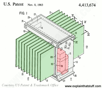
Artwork: Large transformers have built-in cooling systems. In this case, the transformer core and coil (red) sit inside a large oil tank (gray). Hot oil taken from the top of the tank circulates through one or more heat exchangers, which dissipate the waste heat using cooling fins (green), before returning the oil to the same tank at the bottom. Artwork from US Patent 4,413,674: Transformer Cooling Structure by Randall N. Avery et al, Westinghouse Electric Corp., courtesy of US Patent and Trademark Office.
What are solid-state transformers?
You will have gathered from reading what’s above that transformers can be very big, very clumsy, and sometimes very inefficient.
Since the mid-20th century, all kinds of neat electric tricks that used to be carried out by large (and sometimes mechanical)
components have been done electronically instead, using what’s called “solid-state” technology.
So, for example, switching and amplifying relays have been swapped
for transistors,
while magnetic hard drives have increasingly been replaced by flash memory
(in such things as solid-state drives, SSDs, and USB memory sticks).
Over the last few decades, electronic engineers have been working to develop what are called solid-state transformers (SST).
These are essentially compact, high-power, high-frequency semiconductor circuits that increase or decrease voltages with better reliability and
efficiency than traditional transformers; they’re also much more controllable, so more
responsive to changes in supply and demand. “Smart grids” (future power-transmission systems, fed by intermittent sources of
renewable energy, such as wind turbines and solar farms),
are therefore going to be a major application. Despite huge interest, SST
technology remains relatively little used so far, but it’s likely to be
the most exciting area of transformer design in the future.
Please do NOT copy our articles onto blogs and other websites
Articles from this website are registered at the US Copyright Office. Copying or otherwise using registered works without permission, removing this or other copyright notices, and/or infringing related rights could make you liable to severe civil or criminal penalties.
Text copyright © Chris Woodford 2007, 2021. All rights reserved. Full copyright notice and terms of use.
Follow us
Rate this page
Please rate or give feedback on this page and I will make a donation to WaterAid.
Save or share this page
Press CTRL + D to bookmark this page for later or tell your friends about it with:
Cite this page
Woodford, Chris. (2007/2021) Electricity transformers. Retrieved from https://www.explainthatstuff.com/transformers.html. [Accessed (Insert date here)]


![Toni Kroos là ai? [ sự thật về tiểu sử đầy đủ Toni Kroos ]](https://evbn.org/wp-content/uploads/New-Project-6635-1671934592.jpg)


