
Configuring and managing networking Red Hat Enterprise Linux 8 | Red Hat Customer Portal
A Red Hat training course is available for RHEL 8
Mục Lục
Configuring and managing networking
Red Hat Enterprise Linux
8
Managing network interfaces, firewalls, and advanced networking features
Red Hat
Customer Content Services
Legal Notice
Abstract
The networking capabilities of Red Hat Enterprise Linux (RHEL) enable you to configure your host to meet your organization’s network and security requirements. You can configure Bonds, VLANs, bridges, tunnels and other network types to connect the host to the network.
You can build complex and performance-critical firewalls for the local host and the entire network. Packet filtering software, such as the firewalld service, the nftables framework, and Express Data Path (XDP).
RHEL also supports advanced networking features. For example, with policy-based routing, you can set up complex routing scenarios, and MultiPath TCP (MPTCP) enables clients to roam among different networks without interrupting the TCP connection to the application running on your RHEL server.
Making open source more inclusive
Red Hat is committed to replacing problematic language in our code, documentation, and web properties. We are beginning with these four terms: master, slave, blacklist, and whitelist. Because of the enormity of this endeavor, these changes will be implemented gradually over several upcoming releases. For more details, see our CTO Chris Wright’s message.
Providing feedback on Red Hat documentation
We appreciate your feedback on our documentation. Let us know how we can improve it.
Submitting comments on specific passages
-
View the documentation in the
Multi-page HTML
format and ensure that you see the
Feedback
button in the upper right corner after the page fully loads.
- Use your cursor to highlight the part of the text that you want to comment on.
-
Click the
Add Feedback
button that appears near the highlighted text.
-
Add your feedback and click
Submit
.
Submitting feedback through Bugzilla (account required)
- Log in to the Bugzilla website.
-
Select the correct version from the
Version
menu.
-
Enter a descriptive title in the
Summary
field.
-
Enter your suggestion for improvement in the
Description
field. Include links to the relevant parts of the documentation.
-
Click
Submit Bug
.
Chapter 1. Consistent network interface device naming
The Linux kernel assigns names to network interfaces by combining a fixed prefix and a number that increases as the kernel initializes the network devices. For instance, eth0 represents the first device being probed on start-up. If you add another network interface card to the system, the assignment of the kernel device names is no longer fixed. Consequently, after a reboot, the kernel can name the device differently.
To solve this problem, the udev device manager supports a number of different naming schemes. By default, udev assigns fixed names based on firmware, topology, and location information. This has the following advantages:
- Device names are fully predictable.
- Device names stay fixed even if you add or remove hardware, because no re-enumeration takes place.
- Defective hardware can be seamlessly replaced.
Warning
Red Hat does not support systems with consistent device naming disabled. For further details, see Is it safe to set net.ifnames=0?
1.1. Network interface device naming hierarchy
If consistent device naming is enabled, which is the default in Red Hat Enterprise Linux, the udev device manager generates device names based on the following schemes:
SchemeDescriptionExample
1
Device names incorporate firmware or BIOS-provided index numbers for onboard devices. If this information is not available or applicable, udev uses scheme 2.
eno1
2
Device names incorporate firmware or BIOS-provided PCI Express (PCIe) hot plug slot index numbers. If this information is not available or applicable, udev uses scheme 3.
ens1
3
Device names incorporate the physical location of the connector of the hardware. If this information is not available or applicable, udev uses scheme 5.
enp2s0
4
Device names incorporate the MAC address. Red Hat Enterprise Linux does not use this scheme by default, but administrators can optionally use it.
enx525400d5e0fb
5
The traditional unpredictable kernel naming scheme. If udev cannot apply any of the other schemes, the device manager uses this scheme.
eth0
By default, Red Hat Enterprise Linux selects the device name based on the NamePolicy setting in the /usr/lib/systemd/network/99-default.link file. The order of the values in NamePolicy is important. Red Hat Enterprise Linux uses the first device name that is both specified in the file and that udev generated.
If you manually configured udev rules to change the name of kernel devices, those rules take precedence.
1.2. How the network device renaming works
By default, consistent device naming is enabled in Red Hat Enterprise Linux. The udev device manager processes different rules to rename the devices. The udev service processes these rules in the following order:
-
The
/usr/lib/udev/rules.d/60-net.rulesfile defines that the/lib/udev/rename_devicehelper utility searches for theHWADDRparameter in/etc/sysconfig/network-scripts/ifcfg-*files. If the value set in the variable matches the MAC address of an interface, the helper utility renames the interface to the name set in theDEVICEparameter of the file. -
The
/usr/lib/udev/rules.d/71-biosdevname.rulesfile defines that thebiosdevnameutility renames the interface according to its naming policy, provided that it was not renamed in the previous step. -
The
/usr/lib/udev/rules.d/75-net-description.rulesfile defines thatudevexamines the network interface device and sets the properties inudev-internal variables that will be processed in the next step. Note that some of these properties might be undefined. -
The
/usr/lib/udev/rules.d/80-net-setup-link.rulesfile calls thenet_setup_linkudevbuilt-in which then applies the policy. The following is the default policy that is stored in the/usr/lib/systemd/network/99-default.linkfile:[Link] NamePolicy=kernel database onboard slot path MACAddressPolicy=persistent
With this policy, if the kernel uses a persistent name,
udevdoes not rename the interface. If the kernel does not use a persistent name,udevrenames the interface to the name provided by the hardware database ofudev. If this database is not available, Red Hat Enterprise Linux falls back to the mechanisms described above.Alternatively, set the
NamePolicyparameter in this file tomacfor media access control (MAC) address-based interface names. -
The
/usr/lib/udev/rules.d/80-net-setup-link.rulesfile defines thatudevrenames the interface based on theudev-internal parameters in the following order:-
ID_NET_NAME_ONBOARD -
ID_NET_NAME_SLOT -
ID_NET_NAME_PATH
If one parameter is not set,
udevuses the next one. If none of the parameters are set, the interface is not renamed. -
Steps 3 and 4 implement the naming schemes 1 to 4 described in Network interface device naming hierarchy.
Additional resources
- Customizing the prefix of Ethernet interfaces during the installation
-
systemd.link(5)man page
1.3. Predictable network interface device names on the x86_64 platform explained
When the consistent network device name feature is enabled, the udev device manager creates the names of devices based on different criteria. The interface name starts with a two-character prefix based on the type of interface:
-
enfor Ethernet -
wlfor wireless LAN (WLAN) -
wwfor wireless wide area network (WWAN)
Additionally, one of the following is appended to one of the above-mentioned prefix based on the schema the udev device manager applies:
-
o<on-board_index_number>
-
s<hot_plug_slot_index_number>[f<function>][d<device_id>]Note that all multi-function PCI devices have the
[f<function>]number in the device name, including the function0device. -
x<MAC_address>
-
[P<domain_number>]p<bus>s<slot>[f<function>][d<device_id>]The
[P<domain_number>]part defines the PCI geographical location. This part is only set if the domain number is not0. -
[P<domain_number>]p<bus>s<slot>[f<function>][u<usb_port>][…][c<config>][i<interface>]For USB devices, the full chain of port numbers of hubs is composed. If the name is longer than the maximum (15 characters), the name is not exported. If there are multiple USB devices in the chain,
udevsuppresses the default values for USB configuration descriptors (c1) and USB interface descriptors (i0).
1.4. Predictable network interface device names on the System z platform explained
When the consistent network device name feature is enabled, the udev device manager on the System z platform creates the names of devices based on the bus ID. The bus ID identifies a device in the s390 channel subsystem.
For a channel command word (CCW) device, the bus ID is the device number with a leading 0.n prefix where n is the subchannel set ID.
Ethernet interfaces are named, for example, enccw0.0.1234. Serial Line Internet Protocol (SLIP) channel-to-channel (CTC) network devices are named, for example, slccw0.0.1234.
Use the znetconf -c or the lscss -a commands to display available network devices and their bus IDs.
Red Hat Enterprise Linux also supports predictable and persistent interface names for RDMA over Converged Ethernet (RoCE) Express PCI functions. Two identifiers provide predictable interface names: user identifier (UID) and function identifier (FID). On a system to get UID-based predictable interface names, enforce UID uniqueness, which is the preferred naming scheme. If no unique UIDs are available, then RHEL uses FIDs to set predictable interface names.
1.5. Customizing the prefix of Ethernet interfaces during the installation
You can customize the prefix of Ethernet interface names during the Red Hat Enterprise Linux installation.
Important
Red Hat does not support customizing the prefix using the prefixdevname utility on already deployed systems.
After the RHEL installation, the udev service names Ethernet devices <prefix>.<index>. For example, if you select the prefix net, RHEL names Ethernet interfaces net0, net1, and so on.
Prerequisites
-
The prefix you want to set meets the following requirements:
- It consists of ASCII characters.
- It is an alpha-numeric string.
- It is shorter than 16 characters.
-
It does not conflict with any other well-known prefix used for network interface naming, such as
eth,eno,ens, andem.
Procedure
- Boot the Red Hat Enterprise Linux installation media.
-
In the boot manager:
-
Select the
Install Red Hat Enterprise Linuxentry, and press<version>
Tab
to edit the entry.
-
Append
net.ifnames.prefix=to the kernel options.<prefix>
-
Press
Enter
to start the installer.
-
Select the
- Install Red Hat Enterprise Linux.
Verification
-
After the installation, display the Ethernet interfaces:
#
ip link show
... 2:net0
: <BROADCAST,MULTICAST,UP,LOWER_UP> mtu 1500 qdisc fq_codel state UP mode DEFAULT group default qlen 1000 link/ether 00:53:00:c5:98:1c brd ff:ff:ff:ff:ff:ff 3:net1
: <BROADCAST,MULTICAST,UP,LOWER_UP> mtu 1500 qdisc fq_codel state UP mode DEFAULT group default qlen 1000 link/ether 00:53:00:c2:39:9e brd ff:ff:ff:ff:ff:ff ...
1.6. Assigning user-defined network interface names using udev rules
The udev device manager supports a set of rules to customize the interface names.
Procedure
-
Display all network interfaces and their MAC addresses:
#
ip link list
enp6s0f0: <BROADCAST,MULTICAST,UP,LOWER_UP> mtu 1500 qdisc fq_codel state UP mode DEFAULT group default qlen 1000 link/ether b4:96:91:14:ae:58 brd ff:ff:ff:ff:ff:ff enp6s0f1: <BROADCAST,MULTICAST,UP,LOWER_UP> mtu 1500 qdisc fq_codel state UP mode DEFAULT group default qlen 1000 link/ether b4:96:91:14:ae:5a brd ff:ff:ff:ff:ff:ff enp4s0f0: <BROADCAST,MULTICAST,UP,LOWER_UP> mtu 1500 qdisc fq_codel state UP mode DEFAULT group default qlen 1000 link/ether 00:90:fa:6a:7d:90 brd ff:ff:ff:ff:ff:ff -
Create the file
/etc/udev/rules.d/70-custom-ifnames.ruleswith the following contents:SUBSYSTEM=="net",ACTION=="add",ATTR{address}=="
b4:96:91:14:ae:58
",ATTR{type}=="1
",NAME="provider0
"SUBSYSTEM=="net",ACTION=="add",ATTR{address}=="
b4:96:91:14:ae:5a
",ATTR{type}=="1
",NAME="provider1
"SUBSYSTEM=="net",ACTION=="add",ATTR{address}=="
00:90:fa:6a:7d:90
",ATTR{type}=="1
",NAME="dmz
"These rules match the MAC address of the network interfaces and rename them to the name given in the NAME property. In these examples, ATTR{type} parameter value 1 defines that the interface is of type Ethernet.
Verification
-
Reboot the system.
#
reboot
-
Verify that interface names for each MAC address match the value you set in the
NAMEparameter of the rule file:#
ip link show
provider0: <BROADCAST,MULTICAST,UP,LOWER_UP> mtu 1500 qdisc mq state UP mode DEFAULT group default qlen 1000 link/ether b4:96:91:14:ae:58 brd ff:ff:ff:ff:ff:ff altname enp6s0f0 provider1: <BROADCAST,MULTICAST,UP,LOWER_UP> mtu 1500 qdisc mq state UP mode DEFAULT group default qlen 1000 link/ether b4:96:91:14:ae:5a brd ff:ff:ff:ff:ff:ff altname enp6s0f1 dmz: <BROADCAST,MULTICAST,UP,LOWER_UP> mtu 1500 qdisc mq state UP mode DEFAULT group default qlen 1000 link/ether 00:90:fa:6a:7d:90 brd ff:ff:ff:ff:ff:ff altname enp4s0f0
Additional resources
-
udev(7)man page -
udevadm(8)man page -
/usr/src/kernels/provided by the<kernel_version>
/include/uapi/linux/if_arp.h
kernel-docpackage
1.7. Assigning user-defined network interface names using systemd link files
Create a naming scheme by renaming network interfaces to provider0.
Procedure
-
Display all interfaces names and their MAC addresses:
#
ip link show
enp6s0f0: <BROADCAST,MULTICAST,UP,LOWER_UP> mtu 1500 qdisc fq_codel state UP mode DEFAULT group default qlen 1000 link/ether b4:96:91:14:ae:58 brd ff:ff:ff:ff:ff:ff enp6s0f1: <BROADCAST,MULTICAST,UP,LOWER_UP> mtu 1500 qdisc fq_codel state UP mode DEFAULT group default qlen 1000 link/ether b4:96:91:14:ae:5a brd ff:ff:ff:ff:ff:ff enp4s0f0: <BROADCAST,MULTICAST,UP,LOWER_UP> mtu 1500 qdisc fq_codel state UP mode DEFAULT group default qlen 1000 link/ether 00:90:fa:6a:7d:90 brd ff:ff:ff:ff:ff:ff -
For naming the interface with MAC address b4:96:91:14:ae:58 to provider0, create the /etc/systemd/network/70-custom-ifnames.link file with following contents:
[Match]
MACAddress=
b4:96:91:14:ae:58
[Link]
Name=
provider0
This link file matches a MAC address and renames the network interface to the name set in the
Nameparameter.
Verification
-
Reboot the system:
#
reboot
-
Verify that the device with the MAC address you specified in the link file has been assigned to
provider0:#
ip link show
provider0: <BROADCAST,MULTICAST,UP,LOWER_UP> mtu 1500 qdisc mq state UP mode DEFAULT group default qlen 1000 link/ether b4:96:91:14:ae:58 brd ff:ff:ff:ff:ff:ff
Additional resources
-
systemd.link(5)man page
Chapter 2. Configuring an Ethernet connection
Red Hat Enterprise Linux provides administrators different options to configure Ethernet connections. For example:
-
Use
nmclito configure connections on the command line. -
Use
nmtuito configure connections in a text-based user interface. - Use RHEL System Roles to automate the configuration of connections on one or multiple hosts.
-
Use the GNOME Settings menu or
nm-connection-editorapplication to configure connections in a graphical interface. -
Use
nmstatectlto configure connections through the Nmstate API.
Note
If you want to manually configure Ethernet connections on hosts running in the Microsoft Azure cloud, disable the cloud-init service or configure it to ignore the network settings retrieved from the cloud environment. Otherwise, cloud-init will override on the next reboot the network settings that you have manually configured.
2.1. Configuring a static Ethernet connection using nmcli
To configure an Ethernet connection on the command line, use the nmcli utility.
For example, the procedure below creates a NetworkManager connection profile for the enp7s0 device with the following settings:
-
A static IPv4 address –
192.0.2.1with a/24subnet mask -
A static IPv6 address –
2001:db8:1::1with a/64subnet mask -
An IPv4 default gateway –
192.0.2.254 -
An IPv6 default gateway –
2001:db8:1::fffe -
An IPv4 DNS server –
192.0.2.200 -
An IPv6 DNS server –
2001:db8:1::ffbb -
A DNS search domain –
example.com
Prerequisites
- A physical or virtual Ethernet device exists in the server’s configuration.
Procedure
-
Add a new NetworkManager connection profile for the Ethernet connection:
#
nmcli connection add con-name
Example-Connection
ifnameenp7s0
type ethernetThe further steps modify the
Example-Connectionconnection profile you created. -
Set the IPv4 address:
#
nmcli connection modify
Example-Connection
ipv4.addresses192.0.2.1/24
-
Set the IPv6 address:
#
nmcli connection modify
Example-Connection
ipv6.addresses2001:db8:1::1/64
-
Set the IPv4 and IPv6 connection method to
manual:#
nmcli connection modify
#Example-Connection
ipv4.method manualnmcli connection modify
Example-Connection
ipv6.method manual -
Set the IPv4 and IPv6 default gateways:
#
nmcli connection modify
#Example-Connection
ipv4.gateway192.0.2.254
nmcli connection modify
Example-Connection
ipv6.gateway2001:db8:1::fffe
-
Set the IPv4 and IPv6 DNS server addresses:
#
nmcli connection modify
#Example-Connection
ipv4.dns "192.0.2.200
"nmcli connection modify
Example-Connection
ipv6.dns "2001:db8:1::ffbb
"To set multiple DNS servers, specify them space-separated and enclosed in quotes.
-
Set the DNS search domain for the IPv4 and IPv6 connection:
#
nmcli connection modify
#Example-Connection
ipv4.dns-searchexample.com
nmcli connection modify
Example-Connection
ipv6.dns-searchexample.com
-
Activate the connection profile:
#
nmcli connection up
Connection successfully activated (D-Bus active path: /org/freedesktop/NetworkManager/ActiveConnection/Example-Connection
13
)
Verification steps
-
Display the status of the devices and connections:
#
nmcli device status
DEVICE TYPE STATE CONNECTIONenp7s0
ethernetconnected
Example-Connection
-
Use the
pingutility to verify that this host can send packets to other hosts:#
ping
host_name_or_IP_address
Troubleshooting
- Make sure that the network cable is plugged-in to the host and a switch.
- Check whether the link failure exists only on this host or also on other hosts connected to the same switch.
- Verify that the network cable and the network interface are working as expected. Perform hardware diagnosis steps and replace defect cables and network interface cards.
- If the configuration on the disk does not match the configuration on the device, starting or restarting NetworkManager creates an in-memory connection that reflects the configuration of the device. For further details and how to avoid this problem, see NetworkManager duplicates a connection after restart of NetworkManager service.
Additional resources
-
nm-settings(5)man page -
nmcli(1)man page - Configuring NetworkManager to avoid using a specific profile to provide a default gateway
2.2. Configuring a static Ethernet connection using the nmcli interactive editor
You can configure an Ethernet connection on the command line using the interactive mode of the nmcli utility.
For example, the procedure below creates a NetworkManager connection profile for the enp7s0 device with the following settings:
-
A static IPv4 address –
192.0.2.1with a/24subnet mask -
A static IPv6 address –
2001:db8:1::1with a/64subnet mask -
An IPv4 default gateway –
192.0.2.254 -
An IPv6 default gateway –
2001:db8:1::fffe -
An IPv4 DNS server –
192.0.2.200 -
An IPv6 DNS server –
2001:db8:1::ffbb -
A DNS search domain –
example.com
Prerequisites
- A physical or virtual Ethernet device exists in the server’s configuration.
Procedure
-
To add a new NetworkManager connection profile for the Ethernet connection, and starting the interactive mode, enter:
#
nmcli connection edit type ethernet con-name
Example-Connection
-
Set the network interface:
nmcli>
set connection.interface-nameenp7s0
-
Set the IPv4 address:
nmcli>
set ipv4.addresses192.0.2.1/24
-
Set the IPv6 address:
nmcli>
set ipv6.addresses2001:db8:1::1/64
-
Set the IPv4 and IPv6 connection method to
manual:nmcli>
set ipv4.method manualnmcli>set ipv6.method manual -
Set the IPv4 and IPv6 default gateways:
nmcli>
set ipv4.gatewaynmcli>192.0.2.254
set ipv6.gateway2001:db8:1::fffe
-
Set the IPv4 and IPv6 DNS server addresses:
nmcli>
set ipv4.dnsnmcli>192.0.2.200
set ipv6.dns2001:db8:1::ffbb
To set multiple DNS servers, specify them space-separated and enclosed in quotation marks.
-
Set the DNS search domain for the IPv4 and IPv6 connection:
nmcli>
set ipv4.dns-searchnmcli>example.com
set ipv6.dns-searchexample.com
-
Save and activate the connection:
nmcli>
save persistentSaving the connection with 'autoconnect=yes'. That might result in an immediate activation of the connection. Do you still want to save? (yes/no) [yes]yes -
Leave the interactive mode:
nmcli>
quit
Verification steps
-
Display the status of the devices and connections:
#
nmcli device status
DEVICE TYPE STATE CONNECTIONenp7s0
ethernetconnected
Example-Connection
-
Use the
pingutility to verify that this host can send packets to other hosts:#
ping
host_name_or_IP_address
Troubleshooting
- Make sure that the network cable is plugged-in to the host and a switch.
- Check whether the link failure exists only on this host or also on other hosts connected to the same switch.
- Verify that the network cable and the network interface are working as expected. Perform hardware diagnosis steps and replace defect cables and network interface cards.
- If the configuration on the disk does not match the configuration on the device, starting or restarting NetworkManager creates an in-memory connection that reflects the configuration of the device. For further details and how to avoid this problem, see NetworkManager duplicates a connection after restart of NetworkManager service.
Additional resources
-
nm-settings(5)man page -
nmcli(1)man page - Configuring NetworkManager to avoid using a specific profile to provide a default gateway
2.3. Configuring a static Ethernet connection using nmtui
The nmtui application provides a text-based user interface for NetworkManager. You can use nmtui to configure an Ethernet connection with a static IP address on a host without a graphical interface.
Note
In nmtui:
- Navigate by using the cursor keys.
-
Press a button by selecting it and hitting
Enter
.
-
Select and deselect checkboxes by using
Space
.
Prerequisites
- A physical or virtual Ethernet device exists in the server’s configuration.
Procedure
-
If you do not know the network device name you want to use in the connection, display the available devices:
#
nmcli device status
DEVICE TYPE STATE CONNECTIONenp7s0
ethernet unavailable -- ... -
Start
nmtui:#
nmtui
-
Select
Edit a connection, and pressEnter
.
-
Press the
Addbutton. -
Select
Ethernetfrom the list of network types, and pressEnter
.
- Optional: Enter a name for the NetworkManager profile to be created.
-
Enter the network device name into the
Devicefield. -
Configure the IPv4 and IPv6 address settings in the
IPv4 configurationandIPv6 configurationareas:-
Press the
Automaticbutton, and selectManualfrom the displayed list. -
Press the
Showbutton next to the protocol you want to configure to display additional fields. -
Press the
Addbutton next toAddresses, and enter the IP address and the subnet mask in Classless Inter-Domain Routing (CIDR) format.If you do not specify a subnet mask, NetworkManager sets a
/32subnet mask for IPv4 addresses and/64for IPv6 addresses. - Enter the address of the default gateway.
-
Press the
Addbutton next toDNS servers, and enter the DNS server address. -
Press the
Addbutton next toSearch domains, and enter the DNS search domain.
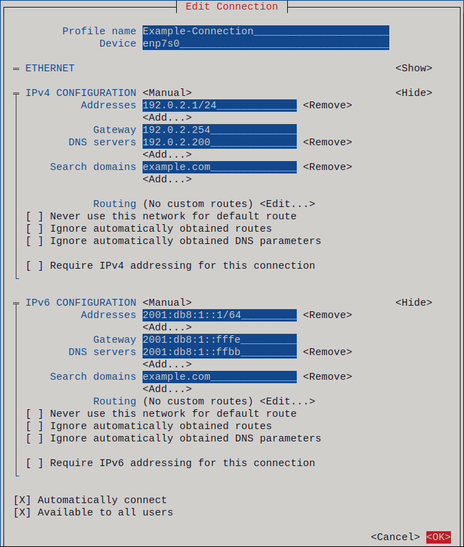
Figure 2.1. Example of an Ethernet connection with static IP address settings
-
Press the
-
Press the
OKbutton to create and automatically activate the new connection. -
Press the
Backbutton to return to the main menu. -
Select
Quit, and pressEnter
to close the
nmtuiapplication.
Verification
-
Display the status of the devices and connections:
#
nmcli device status
DEVICE TYPE STATE CONNECTIONenp7s0
ethernetconnected
Example-Connection
-
Use the
pingutility to verify that this host can send packets to other hosts:#
ping
host_name_or_IP_address
Troubleshooting
- Make sure that the network cable is plugged-in to the host and a switch.
- Check whether the link failure exists only on this host or also on other hosts connected to the same switch.
- Verify that the network cable and the network interface are working as expected. Perform hardware diagnosis steps and replace defect cables and network interface cards.
- If the configuration on the disk does not match the configuration on the device, starting or restarting NetworkManager creates an in-memory connection that reflects the configuration of the device. For further details and how to avoid this problem, see NetworkManager duplicates a connection after restart of NetworkManager service.
Additional resources
- Configuring NetworkManager to avoid using a specific profile to provide a default gateway
2.4. Configuring a static Ethernet connection using nmstatectl
To configure an Ethernet connection using the Nmstate API, use the nmstatectl utility.
For example, the procedure below creates a NetworkManager connection profile for the enp7s0 device with the following settings:
-
A static IPv4 address –
192.0.2.1with the/24subnet mask -
A static IPv6 address –
2001:db8:1::1with the/64subnet mask -
An IPv4 default gateway –
192.0.2.254 -
An IPv6 default gateway –
2001:db8:1::fffe -
An IPv4 DNS server –
192.0.2.200 -
An IPv6 DNS server –
2001:db8:1::ffbb -
A DNS search domain –
example.com
The nmstatectl utility ensures that, after setting the configuration, the result matches the configuration file. If anything fails, nmstatectl automatically rolls back the changes to avoid leaving the system in an incorrect state.
The procedure defines the interface configuration in YAML format. Alternatively, you can also specify the configuration in JSON format.
Prerequisites
- A physical or virtual Ethernet device exists in the server’s configuration.
-
The
nmstatepackage is installed.
Procedure
-
Create a YAML file, for example
~/create-ethernet-profile.yml, with the following contents:--- interfaces: - name: enp7s0 type: ethernet state: up ipv4: enabled: true address: - ip: 192.0.2.1 prefix-length: 24 dhcp: false ipv6: enabled: true address: - ip: 2001:db8:1::1 prefix-length: 64 autoconf: false dhcp: false routes: config: - destination: 0.0.0.0/0 next-hop-address: 192.0.2.254 next-hop-interface: enp7s0 - destination: ::/0 next-hop-address: 2001:db8:1::fffe next-hop-interface: enp7s0 dns-resolver: config: search: - example.com server: - 192.0.2.200 - 2001:db8:1::ffbb -
Apply the settings to the system:
#
nmstatectl apply ~/create-ethernet-profile.yml
Verification steps
-
Display the status of the devices and connections:
#
nmcli device status
DEVICE TYPE STATE CONNECTIONenp7s0
ethernetconnected
enp7s0
-
Display all settings of the connection profile:
#
nmcli connection show
connection.id:enp7s0
enp7s0
connection.uuid:b6cdfa1c-e4ad-46e5-af8b-a75f06b79f76
connection.stable-id: -- connection.type: 802-3-ethernet connection.interface-name:enp7s0
... -
Display the connection settings in YAML format:
#
nmstatectl show
enp7s0
Additional resources
-
nmstatectl(8)man page -
/usr/share/doc/nmstate/examples/directory
2.5. Configuring a static Ethernet connection using RHEL System Roles with the interface name
You can remotely configure an Ethernet connection using the network RHEL System Role.
For example, the procedure below creates a NetworkManager connection profile for the enp7s0 device with the following settings:
-
A static IPv4 address –
192.0.2.1with a/24subnet mask -
A static IPv6 address –
2001:db8:1::1with a/64subnet mask -
An IPv4 default gateway –
192.0.2.254 -
An IPv6 default gateway –
2001:db8:1::fffe -
An IPv4 DNS server –
192.0.2.200 -
An IPv6 DNS server –
2001:db8:1::ffbb -
A DNS search domain –
example.com
Perform this procedure on the Ansible control node.
Prerequisites
- You have prepared the control node and the managed nodes
- You are logged in to the control node as a user who can run playbooks on the managed nodes.
-
The account you use to connect to the managed nodes has
sudopermissions on them. - The hosts or host groups on which you to want run this playbook are listed in the Ansible inventory file.
- A physical or virtual Ethernet device exists in the server’s configuration.
- The managed nodes use NetworkManager to configure the network.
Procedure
-
Create a playbook file, for example
~/ethernet-static-IP.yml, with the following content:--- - name: Configure the network hosts:
managed-node-01.example.com
tasks: - name: Configure an Ethernet connection with static IP include_role: name: rhel-system-roles.network vars: network_connections: - name: enp7s0 interface_name: enp7s0 type: ethernet autoconnect: yes ip: address: - 192.0.2.1/24 - 2001:db8:1::1/64 gateway4: 192.0.2.254 gateway6: 2001:db8:1::fffe dns: - 192.0.2.200 - 2001:db8:1::ffbb dns_search: - example.com state: up -
Run the playbook:
#
ansible-playbook
~/ethernet-static-IP.yml
Additional resources
-
/usr/share/ansible/roles/rhel-system-roles.network/README.mdfile
2.6. Configuring a static Ethernet connection using RHEL System Roles with a device path
You can remotely configure an Ethernet connection using the network RHEL System Role.
You can identify the device path with the following command:
#udevadm info /sys/class/net/
<device_name>
| grep ID_PATH=
For example, the procedure below creates a NetworkManager connection profile with the following settings for the device that matches the PCI ID 0000:00:0[1-3].0 expression, but not 0000:00:02.0:
-
A static IPv4 address –
192.0.2.1with a/24subnet mask -
A static IPv6 address –
2001:db8:1::1with a/64subnet mask -
An IPv4 default gateway –
192.0.2.254 -
An IPv6 default gateway –
2001:db8:1::fffe -
An IPv4 DNS server –
192.0.2.200 -
An IPv6 DNS server –
2001:db8:1::ffbb -
A DNS search domain –
example.com
Perform this procedure on the Ansible control node.
Prerequisites
- You have prepared the control node and the managed nodes
- You are logged in to the control node as a user who can run playbooks on the managed nodes.
-
The account you use to connect to the managed nodes has
sudopermissions on them. - The hosts or host groups on which you want to run this playbook are listed in the Ansible inventory file.
- A physical or virtual Ethernet device exists in the server’s configuration.
- The managed nodes use NetworkManager to configure the network.
Procedure
-
Create a playbook file, for example
~/ethernet-static-IP.yml, with the following content:--- - name: Configure the network hosts:
managed-node-01.example.com
tasks: - name: Configure an Ethernet connection with dynamic IP include_role: name: rhel-system-roles.network vars: network_connections: - name:example
match: path: -pci-0000:00:0[1-3].0
-&!pci-0000:00:02.0
type: ethernet autoconnect:yes
ip: address: -192.0.2.1/24
-2001:db8:1::1/64
gateway4:192.0.2.254
gateway6:2001:db8:1::fffe
dns: -192.0.2.200
-2001:db8:1::ffbb
dns_search: -example.com
state:up
The
matchparameter in this example defines that Ansible applies the play to devices that match PCI ID0000:00:0[1-3].0, but not0000:00:02.0. For further details about special modifiers and wild cards you can use, see thematchparameter description in the/usr/share/ansible/roles/rhel-system-roles.network/README.mdfile. -
Run the playbook:
#
ansible-playbook
~/ethernet-static-IP.yml
Additional resources
-
/usr/share/ansible/roles/rhel-system-roles.network/README.mdfile
2.7. Configuring a dynamic Ethernet connection using nmcli
To configure an Ethernet connection on the command line, use the nmcli utility. For connections with dynamic IP address settings, NetworkManager requests the IP settings for the connection from a DHCP server.
Prerequisites
- A physical or virtual Ethernet device exists in the server’s configuration.
- A DHCP server is available in the network.
Procedure
-
Add a new NetworkManager connection profile for the Ethernet connection:
#
nmcli connection add con-name
Example-Connection
ifnameenp7s0
type ethernet -
Optionally, change the host name NetworkManager sends to the DHCP server when using the
Example-Connectionprofile:#
nmcli connection modify
Example-Connection
ipv4.dhcp-hostnameExample
ipv6.dhcp-hostnameExample
-
Optionally, change the client ID NetworkManager sends to an IPv4 DHCP server when using the
Example-Connectionprofile:#
nmcli connection modify
Example-Connection
ipv4.dhcp-client-idclient-ID
Note that there is no
dhcp-client-idparameter for IPv6. To create an identifier for IPv6, configure thedhclientservice.
Verification steps
-
Display the status of the devices and connections:
#
nmcli device status
DEVICE TYPE STATE CONNECTIONenp7s0
ethernetconnected
Example-Connection
-
Use the
pingutility to verify that this host can send packets to other hosts:#
ping
host_name_or_IP_address
Troubleshooting
- Make sure that the network cable is plugged-in to the host and a switch.
- Check whether the link failure exists only on this host or also on other hosts connected to the same switch.
- Verify that the network cable and the network interface are working as expected. Perform hardware diagnosis steps and replace defect cables and network interface cards.
- If the configuration on the disk does not match the configuration on the device, starting or restarting NetworkManager creates an in-memory connection that reflects the configuration of the device. For further details and how to avoid this problem, see NetworkManager duplicates a connection after restart of NetworkManager service.
Additional resources
-
dhclient(8)man page -
nm-settings(5) -
nmcli(1)man page - Configuring NetworkManager to avoid using a specific profile to provide a default gateway
2.8. Configuring a dynamic Ethernet connection using the nmcli interactive editor
You can configure an Ethernet connection on the command line using the interactive mode of the nmcli utility. For connections with dynamic IP address settings, NetworkManager requests the IP settings for the connection from a DHCP server.
Prerequisites
- A physical or virtual Ethernet device exists in the server’s configuration.
- A DHCP server is available in the network.
Procedure
-
To add a new NetworkManager connection profile for the Ethernet connection, and starting the interactive mode, enter:
#
nmcli connection edit type ethernet con-name Example-Connection
-
Set the network interface:
nmcli>
set connection.interface-nameenp7s0
-
Optionally, change the host name NetworkManager sends to the DHCP server when using the
Example-Connectionprofile:nmcli>
set ipv4.dhcp-hostnamenmcli>Example
set ipv6.dhcp-hostnameExample
-
Optionally, change the client ID NetworkManager sends to an IPv4 DHCP server when using the
Example-Connectionprofile:nmcli>
set ipv4.dhcp-client-idclient-ID
Note that there is no
dhcp-client-idparameter for IPv6. To create an identifier for IPv6, configure thedhclientservice. -
Save and activate the connection:
nmcli>
save persistentSaving the connection with 'autoconnect=yes'. That might result in an immediate activation of the connection. Do you still want to save? (yes/no) [yes]yes -
Leave the interactive mode:
nmcli>
quit
Verification steps
-
Display the status of the devices and connections:
#
nmcli device status
DEVICE TYPE STATE CONNECTIONenp7s0
ethernetconnected
Example-Connection
-
Use the
pingutility to verify that this host can send packets to other hosts:#
ping
host_name_or_IP_address
Troubleshooting
- Make sure that the network cable is plugged-in to the host and a switch.
- Check whether the link failure exists only on this host or also on other hosts connected to the same switch.
- Verify that the network cable and the network interface are working as expected. Perform hardware diagnosis steps and replace defect cables and network interface cards.
- If the configuration on the disk does not match the configuration on the device, starting or restarting NetworkManager creates an in-memory connection that reflects the configuration of the device. For further details and how to avoid this problem, see NetworkManager duplicates a connection after restart of NetworkManager service.
Additional resources
-
nm-settings(5)man page -
nmcli(1)man page - Configuring NetworkManager to avoid using a specific profile to provide a default gateway
2.9. Configuring a dynamic Ethernet connection using nmtui
The nmtui application provides a text-based user interface for NetworkManager. You can use nmtui to configure an Ethernet connection with a dynamic IP address on a host without a graphical interface.
Note
In nmtui:
- Navigate by using the cursor keys.
-
Press a button by selecting it and hitting
Enter
.
-
Select and deselect checkboxes by using
Space
.
Prerequisites
- A physical or virtual Ethernet device exists in the server’s configuration.
- A DHCP server is available in the network.
Procedure
-
If you do not know the network device name you want to use in the connection, display the available devices:
#
nmcli device status
DEVICE TYPE STATE CONNECTIONenp7s0
ethernet unavailable -- ... -
Start
nmtui:#
nmtui
-
Select
Edit a connection, and pressEnter
.
-
Press the
Addbutton. -
Select
Ethernetfrom the list of network types, and pressEnter
.
- Optional: Enter a name for the NetworkManager profile to be created.
-
Enter the network device name into the
Devicefield. -
Press the
OKbutton to create and automatically activate the new connection.
-
Press the
Backbutton to return to the main menu. -
Select
Quit, and pressEnter
to close the
nmtuiapplication.
Verification
-
Display the status of the devices and connections:
#
nmcli device status
DEVICE TYPE STATE CONNECTIONenp7s0
ethernetconnected
Example-Connection
-
Use the
pingutility to verify that this host can send packets to other hosts:#
ping
host_name_or_IP_address
Troubleshooting
- Make sure that the network cable is plugged-in to the host and a switch.
- Check whether the link failure exists only on this host or also on other hosts connected to the same switch.
- Verify that the network cable and the network interface are working as expected. Perform hardware diagnosis steps and replace defect cables and network interface cards.
- If the configuration on the disk does not match the configuration on the device, starting or restarting NetworkManager creates an in-memory connection that reflects the configuration of the device. For further details and how to avoid this problem, see NetworkManager duplicates a connection after restart of NetworkManager service.
Additional resources
- Configuring NetworkManager to avoid using a specific profile to provide a default gateway
2.10. Configuring a dynamic Ethernet connection using nmstatectl
To configure an Ethernet connection using the Nmstate API, use the nmstatectl utility. For connections with dynamic IP address settings, NetworkManager requests the IP settings for the connection from a DHCP server.
The nmstatectl utility ensures that, after setting the configuration, the result matches the configuration file. If anything fails, nmstatectl automatically rolls back the changes to avoid leaving the system in an incorrect state.
The procedure defines the interface configuration in YAML format. Alternatively, you can also specify the configuration in JSON format.
Prerequisites
- A physical or virtual Ethernet device exists in the server’s configuration.
- A DHCP server is available in the network.
-
The
nmstatepackage is installed.
Procedure
-
Create a YAML file, for example
~/create-ethernet-profile.yml, with the following contents:--- interfaces: - name: enp7s0 type: ethernet state: up ipv4: enabled: true auto-dns: true auto-gateway: true auto-routes: true dhcp: true ipv6: enabled: true auto-dns: true auto-gateway: true auto-routes: true autoconf: true dhcp: true -
Apply the settings to the system:
#
nmstatectl apply ~/create-ethernet-profile.yml
Verification steps
-
Display the status of the devices and connections:
#
nmcli device status
DEVICE TYPE STATE CONNECTIONenp7s0
ethernetconnected
enp7s0
-
Display all settings of the connection profile:
#
nmcli connection show
connection.id:enp7s0
enp7s0
_ connection.uuid:b6cdfa1c-e4ad-46e5-af8b-a75f06b79f76
connection.stable-id: -- connection.type: 802-3-ethernet connection.interface-name:enp7s0
... -
Display the connection settings in YAML format:
#
nmstatectl show
enp7s0
Additional resources
-
nmstatectl(8)man page -
/usr/share/doc/nmstate/examples/directory
2.11. Configuring a dynamic Ethernet connection using RHEL System Roles with the interface name
You can remotely configure an Ethernet connection using the network RHEL System Role. For connections with dynamic IP address settings, NetworkManager requests the IP settings for the connection from a DHCP server.
Perform this procedure on the Ansible control node.
Prerequisites
- You have prepared the control node and the managed nodes
- You are logged in to the control node as a user who can run playbooks on the managed nodes.
-
The account you use to connect to the managed nodes has
sudopermissions on them. - The hosts or host groups on which you want to run this playbook are listed in the Ansible inventory file.
- A physical or virtual Ethernet device exists in the server’s configuration.
- A DHCP server is available in the network
- The managed nodes use NetworkManager to configure the network.
Procedure
-
Create a playbook file, for example
~/ethernet-dynamic-IP.yml, with the following content:--- - name: Configure the network hosts:
managed-node-01.example.com
tasks: - name: Configure an Ethernet connection with dynamic IP include_role: name: rhel-system-roles.network vars: network_connections: - name: enp7s0 interface_name: enp7s0 type: ethernet autoconnect: yes ip: dhcp4: yes auto6: yes state: up -
Run the playbook:
#
ansible-playbook
~/ethernet-dynamic-IP.yml
Additional resources
-
/usr/share/ansible/roles/rhel-system-roles.network/README.mdfile
2.12. Configuring a dynamic Ethernet connection using RHEL System Roles with a device path
You can remotely configure an Ethernet connection using the network RHEL System Role. For connections with dynamic IP address settings, NetworkManager requests the IP settings for the connection from a DHCP server.
You can identify the device path with the following command:
#udevadm info /sys/class/net/
<device_name>
| grep ID_PATH=
Perform this procedure on the Ansible control node.
Prerequisites
- You have prepared the control node and the managed nodes
- You are logged in to the control node as a user who can run playbooks on the managed nodes.
-
The account you use to connect to the managed nodes has
sudopermissions on them. - The hosts or host groups on which you want to run this playbook are listed in the Ansible inventory file.
- A physical or virtual Ethernet device exists in the server’s configuration.
- A DHCP server is available in the network.
- The managed hosts use NetworkManager to configure the network.
Procedure
-
Create a playbook file, for example
~/ethernet-dynamic-IP.yml, with the following content:--- - name: Configure the network hosts:
managed-node-01.example.com
tasks: - name: Configure an Ethernet connection with dynamic IP include_role: name: rhel-system-roles.network vars: network_connections: - name: example match: path: - pci-0000:00:0[1-3].0 - &!pci-0000:00:02.0 type: ethernet autoconnect: yes ip: dhcp4: yes auto6: yes state: upThe
matchparameter in this example defines that Ansible applies the play to devices that match PCI ID0000:00:0[1-3].0, but not0000:00:02.0. For further details about special modifiers and wild cards you can use, see thematchparameter description in the/usr/share/ansible/roles/rhel-system-roles.network/README.mdfile. -
Run the playbook:
#
ansible-playbook
~/ethernet-dynamic-IP.yml
Additional resources
-
/usr/share/ansible/roles/rhel-system-roles.network/README.mdfile
2.13. Configuring an Ethernet connection using control-center
Ethernet connections are the most frequently used connections types in physical or virtual machines. If you use Red Hat Enterprise Linux with a graphical interface, you can configure this connection type in the GNOME control-center.
Note that control-center does not support as many configuration options as the nm-connection-editor application or the nmcli utility.
Prerequisites
- A physical or virtual Ethernet device exists in the server’s configuration.
- GNOME is installed.
Procedure
-
Press the
Super
key, enter
Settings, and pressEnter
.
-
Select
Networkin the navigation on the left. -
Click the
button next to the
Wiredentry to create a new profile. -
Optional: Set a name for the connection on the
Identitytab. -
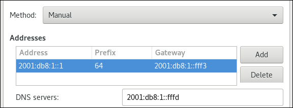
On the
IPv4tab, configure the IPv4 settings. For example, select methodManual, set a static IPv4 address, network mask, default gateway, and DNS server:
-
On the
IPv6tab, configure the IPv6 settings. For example, select methodManual, set a static IPv6 address, network mask, default gateway, and DNS server:
-
Click the
button to save the connection. The GNOME
control-centerautomatically activates the connection.
Verification steps
-
Display the status of the devices and connections:
#
nmcli device status
DEVICE TYPE STATE CONNECTIONenp7s0
ethernetconnected
Example-Connection
-
Use the
pingutility to verify that this host can send packets to other hosts:#
ping
host_name_or_IP_address
Troubleshooting steps
- Make sure that the network cable is plugged-in to the host and a switch.
- Check whether the link failure exists only on this host or also on other hosts connected to the same switch.
- Verify that the network cable and the network interface are working as expected. Perform hardware diagnosis steps and replace defect cables and network interface cards.
- If the configuration on the disk does not match the configuration on the device, starting or restarting NetworkManager creates an in-memory connection that reflects the configuration of the device. For further details and how to avoid this problem, see NetworkManager duplicates a connection after restart of NetworkManager service.
Additional Resources
- Configuring NetworkManager to avoid using a specific profile to provide a default gateway
2.14. Configuring an Ethernet connection using nm-connection-editor
Ethernet connections are the most frequently used connection types in physical or virtual servers. If you use Red Hat Enterprise Linux with a graphical interface, you can configure this connection type using the nm-connection-editor application.
Prerequisites
- A physical or virtual Ethernet device exists in the server’s configuration.
- GNOME is installed.
Procedure
-
Open a terminal, and enter:
$ nm-connection-editor
-
Click the
button to add a new connection.
-
Select the
Ethernetconnection type, and click.
-
On the
Generaltab:-
To automatically enable this connection when the system boots or when you restart the
NetworkManagerservice:-
Select
Connect automatically with priority. -
Optional: Change the priority value next to
Connect automatically with priority.If multiple connection profiles exist for the same device, NetworkManager enables only one profile. By default, NetworkManager activates the last-used profile that has auto-connect enabled. However, if you set priority values in the profiles, NetworkManager activates the profile with the highest priority.
-
Select
-
Clear the
All users may connect to this networkcheck box if the profile should be available only to the user that created the connection profile.

-
-
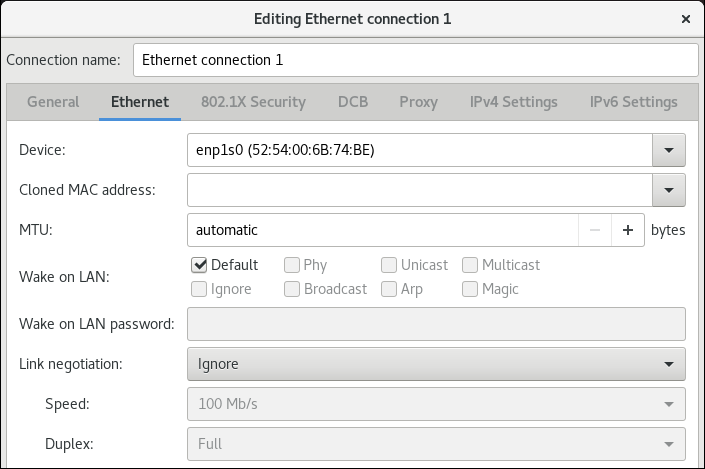
On the
Ethernettab, select a device and, optionally, further Ethernet-related settings.
-
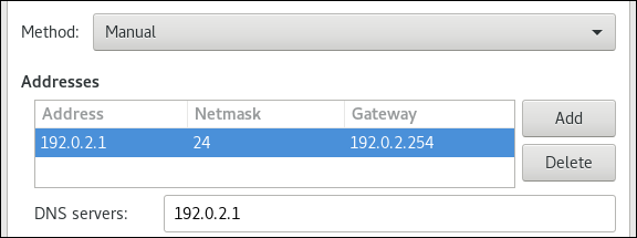
On the
IPv4 Settingstab, configure the IPv4 settings. For example, set a static IPv4 address, network mask, default gateway, and DNS server:
-
On the
IPv6 Settingstab, configure the IPv6 settings. For example, set a static IPv6 address, network mask, default gateway, and DNS server:
- Save the connection.
-
Close
nm-connection-editor.
Verification steps
-
Display the status of the devices and connections:
#
nmcli device status
DEVICE TYPE STATE CONNECTIONenp7s0
ethernetconnected
Example-Connection
-
Use the
pingutility to verify that this host can send packets to other hosts:#
ping
host_name_or_IP_address
Additional Resources
- Configuring NetworkManager to avoid using a specific profile to provide a default gateway
2.15. Changing the DHCP client of NetworkManager
By default, NetworkManager uses its internal DHCP client. However, if you require a DHCP client with features that the built-in client does not provide, you can alternatively configure NetworkManager to use dhclient.
Note that RHEL does not provide dhcpcd and, therefore, NetworkManager can not use this client.
Procedure
-
Create the
/etc/NetworkManager/conf.d/dhcp-client.conffile with the following content:[main]
dhcp=dhclient
You can set the
dhcpparameter tointernal(default) ordhclient. -
If you set the
dhcpparameter todhclient, install thedhcp-clientpackage:#
yum install dhcp-client
-
Restart NetworkManager:
#
systemctl restart NetworkManager
Note that the restart temporarily interrupts all network connections.
Verification
-
Search in the
/var/log/messageslog file for an entry similar to the following:Apr 26 09:54:19 server
NetworkManager[27748
]: <info> [1650959659.8483
] dhcp-init: Using DHCP client 'dhclient'This log entry confirms that NetworkManager uses
dhclientas DHCP client.
Additional resources
-
NetworkManager.conf(5)man page
2.16. Configuring the DHCP behavior of a NetworkManager connection
A Dynamic Host Configuration Protocol (DHCP) client requests the dynamic IP address and corresponding configuration information from a DHCP server each time a client connects to the network.
When you configured a connection to retrieve an IP address from a DHCP server, the NetworkManager requests an IP address from a DHCP server. By default, the client waits 45 seconds for this request to be completed. When a DHCP connection is started, a dhcp client requests an IP address from a DHCP server.
Prerequisites
- A connection that uses DHCP is configured on the host.
Procedure
-
Set the
ipv4.dhcp-timeoutandipv6.dhcp-timeoutproperties. For example, to set both options to30seconds, enter:#
nmcli connection modify
connection_name
ipv4.dhcp-timeout 30 ipv6.dhcp-timeout 30Alternatively, set the parameters to
infinityto configure that NetworkManager does not stop trying to request and renew an IP address until it is successful. -
Optional: Configure the behavior if NetworkManager does not receive an IPv4 address before the timeout:
#
nmcli connection modify
connection_name
ipv4.may-failvalue
If you set the
ipv4.may-failoption to:-
yes, the status of the connection depends on the IPv6 configuration:- If the IPv6 configuration is enabled and successful, NetworkManager activates the IPv6 connection and no longer tries to activate the IPv4 connection.
- If the IPv6 configuration is disabled or not configured, the connection fails.
-
no, the connection is deactivated. In this case:-
If the
autoconnectproperty of the connection is enabled, NetworkManager retries to activate the connection as many times as set in theautoconnect-retriesproperty. The default is4. - If the connection still cannot acquire a DHCP address, auto-activation fails. Note that after 5 minutes, the auto-connection process starts again to acquire an IP address from the DHCP server.
-
If the
-
-
Optional: Configure the behavior if NetworkManager does not receive an IPv6 address before the timeout:
#
nmcli connection modify
connection_name
ipv6.may-failvalue
Additional resources
-
nm-settings(5)man page
2.17. Configuring multiple Ethernet interfaces using a single connection profile by interface name
In most cases, one connection profile contains the settings of one network device. However, NetworkManager also supports wildcards when you set the interface name in connection profiles. If a host roams between Ethernet networks with dynamic IP address assignment, you can use this feature to create a single connection profile that you can use for multiple Ethernet interfaces.
Prerequisites
- Multiple physical or virtual Ethernet devices exist in the server’s configuration.
- A DHCP server is available in the network.
- No connection profile exists on the host.
Procedure
-
Add a connection profile that applies to all interface names starting with
enp:#
nmcli connection add con-name
Example
connection.multi-connect multiple match.interface-name enp* type ethernet
Verification steps
-
Display all settings of the single connection profile:
#
nmcli connection show
connection.id: Example ... connection.multi-connect: 3 (multiple) match.interface-name:Example
enp*...3indicates the number of interfaces active on the connection profile at the same time, and not the number of network interfaces in the connection profile. The connection profile uses all devices that match the pattern in thematch.interface-nameparameter and, therefore, the connection profiles have the same Universally Unique Identifier (UUID). -
Display the status of the connections:
# nmcli connection show
NAME                    UUID                    TYPE     DEVICE
...
Example  6f22402e-c0cc-49cf-b702-eaf0cd5ea7d1  ethernet  enp7s0
Example  6f22402e-c0cc-49cf-b702-eaf0cd5ea7d1  ethernet  enp8s0
Example  6f22402e-c0cc-49cf-b702-eaf0cd5ea7d1  ethernet  enp9s0
Additional resources
-
nmcli(1)man page -
nm-settings(5)man page
2.18. Configuring a single connection profile for multiple Ethernet interfaces using PCI IDs
The PCI ID is a unique identifier of the devices connected to the system. The connection profile adds multiple devices by matching interfaces based on a list of PCI IDs. You can use this procedure to connect multiple device PCI IDs to the single connection profile.
Prerequisites
- Multiple physical or virtual Ethernet devices exist in the server’s configuration.
- A DHCP server is available in the network.
- No connection profile exists on the host.
Procedure
-
Identify the device path. For example, to display the device paths of all interfaces starting with
enp, enter :#
udevadm info /sys/class/net/enp* | grep ID_PATH=
... E: ID_PATH=pci-0000:07:00.0 E: ID_PATH=pci-0000:08:00.0 -
Add a connection profile that applies to all PCI IDs matching the
0000:00:0[7-8].0expression:#
nmcli connection add type ethernet connection.multi-connect multiple match.path "pci-0000:07:00.0 pci-0000:08:00.0" con-name
Example
Verification steps
-
Display the status of the connection:
#
nmcli connection show
NAME UUID TYPE DEVICE Example 9cee0958-512f-4203-9d3d-b57af1d88466 ethernet enp7s0 Example 9cee0958-512f-4203-9d3d-b57af1d88466 ethernet enp8s0 ... -
To display all settings of the connection profile:
#
nmcli connection show
connection.id: Example ... connection.multi-connect: 3 (multiple) match.path: pci-0000:07:00.0,pci-0000:08:00.0 ...Example
This connection profile uses all devices with a PCI ID which match the pattern in the
match.pathparameter and, therefore, the connection profiles have the same Universally Unique Identifier (UUID).
Additional resources
-
nmcli(1)man page -
nm-settings(5)man page
Chapter 3. Managing wifi connections
RHEL provides multiple utilities and applications to configure and connect to wifi networks, for example:
-
The
nmcliutility - The GNOME system menu
-
The
GNOME Settingsapplication -
The
nm-connection-editorapplication
3.1. Supported wifi security types
Depending on the security type a wifi network supports, you can transmitted data more or less securely.
Warning
Do not connect to wifi networks that do not use encryption or which support only the insecure WEP or WPA standards.
RHEL 8 supports the following wifi security types:
-
None: Encryption is disabled, and data is transferred in plain text over the network. -
Enhanced Open: With opportunistic wireless encryption (OWE), devices negotiate unique pairwise master keys (PMK) to encrypt connections in wireless networks without authentication. -
WEP 40/128-bit Key (Hex or ASCII): The Wired Equivalent Privacy (WEP) protocol in this mode uses pre-shared keys only in hex or ASCII format. WEP is deprecated and will be removed in RHEL 9.1. -
WEP 128-bit Passphrase. The WEP protocol in this mode uses an MD5 hash of the passphrase to derive a WEP key. WEP is deprecated and will be removed in RHEL 9.1. -
Dynamic WEP (802.1x): A combination of 802.1X and EAP that uses the WEP protocol with dynamic keys. WEP is deprecated and will be removed in RHEL 9.1. -
LEAP: The Lightweight Extensible Authentication Protocol, which was developed by Cisco, is a proprietary version of the extensible authentication protocol (EAP). -
WPA & WPA2 Personal: In personal mode, the Wi-Fi Protected Access (WPA) and Wi-Fi Protected Access 2 (WPA2) authentication methods use a pre-shared key. -
WPA & WPA2 Enterprise: In enterprise mode, WPA and WPA2 use the EAP framework and authenticate users to a remote authentication dial-in user service (RADIUS) server. -
WPA3 Personal: Wi-Fi Protected Access 3 (WPA3) Personal uses simultaneous authentication of equals (SAE) instead of pre-shared keys (PSK) to prevent dictionary attacks. WPA3 uses perfect forward secrecy (PFS).
3.2. Connecting to a WPA2 or WPA3 Personal-protected wifi network using nmcli commands
You can use the nmcli utility to connect to a wifi network. When you attempt to connect to a network for the first time, the utility automatically creates a NetworkManager connection profile for it. If the network requires additional settings, such as static IP addresses, you can then modify the profile after it has been automatically created.
Prerequisites
- A wifi device is installed on the host.
- The wifi device is enabled, if it has a hardware switch.
Procedure
-
If the wifi radio has been disabled in NetworkManager, enable this feature:
#
nmcli radio wifi on
-
Optional: Display the available wifi networks:
# nmcli device wifi list
IN-USE  BSSID              SSID          MODE   CHAN  RATE        SIGNAL  BARS  SECURITY
        00:53:00:2F:3B:08  Office        Infra  44    270 Mbit/s  57      ▂▄▆_  WPA2 WPA3
        00:53:00:15:03:BF  --            Infra  1     130 Mbit/s  48      ▂▄__  WPA2 WPA3
The service set identifier (
SSID) column contains the names of the networks. If the column shows--, the access point of this network does not broadcast an SSID. -
Connect to the wifi network:
#
nmcli device wifi connect
Password:Office
--askwifi-password
If you prefer to set the password in the command instead of entering it interactively, use the
password wifi-passwordoption in the command instead of--ask:#
nmcli device wifi connect
Office
wifi-password
Note that, if the network requires static IP addresses, NetworkManager fails to activate the connection at this point. You can configure the IP addresses in later steps.
-
If the network requires static IP addresses:
-
Configure the IPv4 address settings, for example:
#
nmcli connection modify
Office
ipv4.method manual ipv4.addresses192.0.2.1/24
ipv4.gateway192.0.2.254
ipv4.dns192.0.2.200
ipv4.dns-searchexample.com
-
Configure the IPv6 address settings, for example:
#
nmcli connection modify
Office
ipv6.method manual ipv6.addresses2001:db8:1::1/64
ipv6.gateway2001:db8:1::fffe
ipv6.dns2001:db8:1::ffbb
ipv6.dns-searchexample.com
-
-
Re-activate the connection:
#
nmcli connection up
Office
Verification
-
Display the active connections:
#
nmcli connection show --active
NAME ID TYPE DEVICEOffice
2501eb7e-7b16-4dc6-97ef-7cc460139a58
wifiwlp0s20f3
If the output lists the wifi connection you have created, the connection is active.
-
Ping a hostname or IP address:
#
ping -c 3
example.com
Additional resources
-
nm-settings-nmcli(5)man page
3.3. Configuring a wifi connection using nmtui
The nmtui application provides a text-based user interface for NetworkManager. You can use nmtui to connect to a wifi network.
Note
In nmtui:
- Navigate by using the cursor keys.
-
Press a button by selecting it and hitting
Enter
.
-
Select and deselect checkboxes by using
Space
.
Procedure
-
If you do not know the network device name you want to use in the connection, display the available devices:
#
nmcli device status
DEVICE TYPE STATE CONNECTIONwlp2s0
wifi unavailable -- ... -
Start
nmtui:#
nmtui
-
Select
Edit a connection, and pressEnter
.
-
Press the
Addbutton. -
Select
Wi-Fifrom the list of network types, and pressEnter
.
- Optional: Enter a name for the NetworkManager profile to be created.
-
Enter the network device name into the
Devicefield. -
Enter the name of the Wi-Fi network, the Service Set Identifier (SSID), into the
SSIDfield. -
Leave the
Modefield set to its default,Client. -
Select the
Securityfield, press Enter, and set the authentication type of the network from the list.Depending on the authentication type you have selected,
nmtuidisplays different fields. - Fill the authentication type-related fields.
-
If the Wi-Fi network requires static IP addresses:
-
Press the
Automaticbutton next to the protocol, and selectManualfrom the displayed list. -
Press the
Showbutton next to the protocol you want to configure to display additional fields, and fill them.
-
Press the
-
Press the
OKbutton to create and automatically activate the new connection.
-
Press the
Backbutton to return to the main menu. -
Select
Quit, and pressEnter
to close the
nmtuiapplication.
Verification
-
Display the active connections:
#
nmcli connection show --active
NAME ID TYPE DEVICEOffice
2501eb7e-7b16-4dc6-97ef-7cc460139a58
wifiwlp0s20f3
If the output lists the wifi connection you have created, the connection is active.
-
Ping a hostname or IP address:
#
ping -c 3
example.com
3.4. Connecting to a wifi network using the GNOME system menu
You can use the GNOME system menu to connect to a wifi network. When you connect to a network for the first time, GNOME creates a NetworkManager connection profile for it. If you configure the connection profile to not automatically connect, you can also use the GNOME system menu to manually connect to a wifi network with an existing NetworkManager connection profile.
Note
Using the GNOME system menu to establish a connection to a wifi network for the first time has certain limitations. For example, you can not configure IP address settings. In this case first configure the connections:
-
In the
GNOME settingsapplication -
In the
nm-connection-editorapplication -
Using
nmclicommands
Prerequisites
- A wifi device is installed on the host.
- The wifi device is enabled, if it has a hardware switch.
Procedure
- Open the system menu on the right side of the top bar.
-
Expand the
Wi-Fi Not Connectedentry. -
Click
Select Network: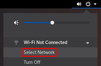
- Select the wifi network you want to connect to.
-
Click
Connect. -
If this is the first time you connect to this network, enter the password for the network, and click
Connect.
Verification
-
Open the system menu on the right side of the top bar, and verify that the wifi network is connected:
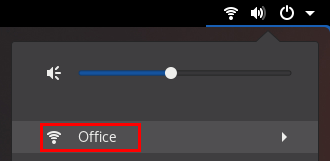
If the network appears in the list, it is connected.
-
Ping a hostname or IP address:
#
ping -c 3
example.com
3.5. Connecting to a wifi network using the GNOME settings application
You can use the GNOME settings application, also named gnome-control-center, to connect to a wifi network and configure the connection. When you connect to the network for the first time, GNOME creates a NetworkManager connection profile for it.
In GNOME settings, you can configure wifi connections for all wifi network security types that RHEL supports.
Prerequisites
- A wifi device is installed on the host.
- The wifi device is enabled, if it has a hardware switch.
Procedure
-
Press the
Super
key, type
Wi-Fi, and pressEnter
.
- Click on the name of the wifi network you want to connect to.
-
Enter the password for the network, and click
Connect. -
If the network requires additional settings, such as static IP addresses or a security type other than WPA2 Personal:
- Click the gear icon next to the network’s name.
-
Optional: Configure the network profile on the
Detailstab to not automatically connect.If you deactivate this feature, you must always manually connect to the network, for example, using
GNOME settingsor the GNOME system menu. -
Configure IPv4 settings on the
IPv4tab, and IPv6 settings on theIPv6tab. -
On the
Securitytab, select the authentication of the network, such asWPA3 Personal, and enter the password.Depending on the selected security, the application shows additional fields. Fill them accordingly. For details, ask the administrator of the wifi network.
-
Click
Apply.
Verification
-
Open the system menu on the right side of the top bar, and verify that the wifi network is connected:
If the network appears in the list, it is connected.
-
Ping a hostname or IP address:
#
ping -c 3
example.com
3.6. Configuring a wifi connection using nm-connection-editor
You can use the nm-connection-editor application to create a connection profile for a wireless network. In this application you can configure all wifi network authentication types that RHEL supports.
By default, NetworkManager enables the auto-connect feature for connection profiles and automatically connects to a saved network if it is available.
Prerequisites
- A wifi device is installed on the host.
- The wifi device is enabled, if it has a hardware switch.
Procedure
-
Open a terminal and enter:
#
nm-connection-editor
-
Click the
button to add a new connection.
-
Select the
Wi-Ficonnection type, and click.
- Optional: Set a name for the connection profile.
-
Optional: Configure the network profile on the
Generaltab to not automatically connect.If you deactivate this feature, you must always manually connect to the network, for example, using
GNOME settingsor the GNOME system menu. -
On the
Wi-Fitab, enter the service set identifier (SSID) in theSSIDfield. -
On the
Wi-Fi Securitytab, select the authentication type for the network, such asWPA3 Personal, and enter the password.Depending on the selected security, the application shows additional fields. Fill them accordingly. For details, ask the administrator of the wifi network.
-
Configure IPv4 settings on the
IPv4tab, and IPv6 settings on theIPv6tab. -
Click
Save. -
Close the
Network Connectionswindow.
Verification
-
Open the system menu on the right side of the top bar, and verify that the wifi network is connected:
If the network appears in the list, it is connected.
-
Ping a hostname or IP address:
#
ping -c 3
example.com
3.7. Configuring a wifi connection with 802.1X network authentication using the RHEL System Roles
Using RHEL System Roles, you can automate the creation of a wifi connection. For example, you can remotely add a wireless connection profile for the wlp1s0 interface using an Ansible playbook. The created profile uses the 802.1X standard to authenticate the client to a wifi network. The playbook configures the connection profile to use DHCP. To configure static IP settings, adapt the parameters in the ip dictionary accordingly.
Perform this procedure on the Ansible control node.
Prerequisites
- You have prepared the control node and the managed nodes
- You are logged in to the control node as a user who can run playbooks on the managed nodes.
-
The account you use to connect to the managed nodes has
sudopermissions on them. - The hosts or host groups on which you want to run this playbook are listed in the Ansible inventory file.
- The network supports 802.1X network authentication.
-
You installed the
wpa_supplicantpackage on the managed node. - DHCP is available in the network of the managed node.
-
The following files required for TLS authentication exist on the control node:
-
The client key is stored in the
/srv/data/client.keyfile. -
The client certificate is stored in the
/srv/data/client.crtfile. -
The CA certificate is stored in the
/srv/data/ca.crtfile.
-
The client key is stored in the
Procedure
-
Create a playbook file, for example
~/enable-802.1x.yml, with the following content:--- - name:
Configure a wifi connection with 802.1X authentication
hosts: "managed-node-01.example.com
" tasks: - name:Copy client key for 802.1X authentication
copy: src: "/srv/data/client.key
" dest: "/etc/pki/tls/private/client.key
" mode: 0400 - name:Copy client certificate for 802.1X authentication
copy: src: "/srv/data/client.crt
" dest: "/etc/pki/tls/certs/client.crt
" - name:Copy CA certificate for 802.1X authentication
copy: src: "/srv/data/ca.crt
" dest: "/etc/pki/ca-trust/source/anchors/ca.crt
" - block: - import_role: name:linux-system-roles.network
vars: network_connections: - name:Configure the Example-wifi profile
interface_name:wlp1s0
state: up type: wireless autoconnect:yes
ip: dhcp4: true auto6: true wireless: ssid: "Example-wifi
" key_mgmt: "wpa-eap
" ieee802_1x: identity: "user_name
" eap: tls private_key: "/etc/pki/tls/client.key
" private_key_password: "password
" private_key_password_flags: none client_cert: "/etc/pki/tls/client.pem
" ca_cert: "/etc/pki/tls/cacert.pem
" domain_suffix_match: "example.com
" -
Run the playbook:
#
ansible-playbook
~/enable-802.1x.yml
Additional resources
-
/usr/share/ansible/roles/rhel-system-roles.network/README.mdfile
3.8. Configuring 802.1X network authentication on an existing wifi connection using nmcli
Using the nmcli utility, you can configure the client to authenticate itself to the network. For example, you can configure Protected Extensible Authentication Protocol (PEAP) authentication with the Microsoft Challenge-Handshake Authentication Protocol version 2 (MSCHAPv2) in an existing NetworkManager wifi connection profile named wlp1s0.
Prerequisites
- The network must have 802.1X network authentication.
- The wifi connection profile exists in NetworkManager and has a valid IP configuration.
-
If the client is required to verify the certificate of the authenticator, the Certificate Authority (CA) certificate must be stored in the
/etc/pki/ca-trust/source/anchors/directory. -
The
wpa_supplicantpackage is installed.
Procedure
-
Set the wifi security mode to
wpa-eap, the Extensible Authentication Protocol (EAP) topeap, the inner authentication protocol tomschapv2, and the user name:#
nmcli connection modify
wlp1s0
wireless-security.key-mgmt wpa-eap 802-1x.eap peap 802-1x.phase2-auth mschapv2 802-1x.identityuser_name
Note that you must set the
wireless-security.key-mgmt,802-1x.eap,802-1x.phase2-auth, and802-1x.identityparameters in a single command. -
Optionally, store the password in the configuration:
#
nmcli connection modify
wlp1s0
802-1x.passwordpassword
Important
By default, NetworkManager stores the password in clear text in the
/etc/sysconfig/network-scripts/keys-connection_namefile, that is readable only by therootuser. However, clear text passwords in a configuration file can be a security risk.To increase the security, set the
802-1x.password-flagsparameter to0x1. With this setting, on servers with the GNOME desktop environment or thenm-appletrunning, NetworkManager retrieves the password from these services. In other cases, NetworkManager prompts for the password. -
If the client is required to verify the certificate of the authenticator, set the
802-1x.ca-certparameter in the connection profile to the path of the CA certificate:#
nmcli connection modify
wlp1s0
802-1x.ca-cert/etc/pki/ca-trust/source/anchors/ca.crt
Note
For security reasons, Red Hat recommends using the certificate of the authenticator to enable clients to validate the identity of the authenticator.
-
Activate the connection profile:
#
nmcli connection up
wlp1s0
Verification steps
- Access resources on the network that require network authentication.
Additional resources
- Managing wifi connections
-
nm-settings(5)man page -
nmcli(1)man page
3.9. Manually setting the wireless regulatory domain
On RHEL, a udev rule executes the setregdomain utility to set the wireless regulatory domain. The utility then provides this information to the kernel.
By default, setregdomain attempts to determine the country code automatically. If this fails, the wireless regulatory domain setting might be wrong. To work around this problem, you can manually set the country code.
Important
Manually setting the regulatory domain disables the automatic detection. Therefore, if you later use the computer in a different country, the previously configured setting might no longer be correct. In this case, remove the /etc/sysconfig/regdomain file to switch back to automatic detection or use this procedure to manually update the regulatory domain setting again.
Procedure
-
Optional: Display the current regulatory domain settings:
#
iw reg get
global countryUS: DFS-FCC
... -
Create the
/etc/sysconfig/regdomainfile with the following content:COUNTRY=
<country_code>
Set the
COUNTRYvariable to an ISO 3166-1 alpha2 country code, such asDEfor Germany orUSfor the United States of America. -
Set the regulatory domain:
#
setregdomain
Verification
-
Display the regulatory domain settings:
#
iw reg get
global countryDE: DFS-ETSI
...
Additional resources
-
setregdomain(1)man page -
iw(8)man page -
regulatory.bin(5)man page - ISO 3166 Country Codes
Chapter 4. Configuring RHEL as a wifi access point
On a host with a wifi device, you can use NetworkManager to configure this host as an access point. Wireless clients can then use the access point to connect to services on the RHEL host or in the network.
When you configure an access point, NetworkManager automatically:
-
Configures the
dnsmasqservice to provide DHCP and DNS services for clients - Enables IP forwarding
-
Adds
nftablesfirewall rules to masquerade traffic from the wifi device and configures IP forwarding
4.1. Identifying whether a wifi device supports the access point mode
To use a wifi device as an access point, the device must support this feature. You can use the nmcli utility to identify if the hardware supports access point mode.
Prerequisites
- A wifi device is installed on the host.
Procedure
-
List the wifi devices to identify the one that should provide the access point:
#
nmcli device status | grep wifi
wlp0s20f3
wifi disconnected -- -
Verify that the device supports the access point mode:
#
nmcli -f WIFI-PROPERTIES.AP device show
WIFI-PROPERTIES.AP: yeswlp0s20f3
4.2. Configuring RHEL as a WPA2 or WPA3 Personal access point
Wi-Fi Protected Access 2 (WPA2) and Wi-Fi Protected Access 3 (WPA3) Personal provide secure authentication methods in wireless networks. Users can connect to the access point using a pre-shared key (PSK).
Prerequisites
- The wifi device supports running in access point mode.
- The wifi device is not in use.
- The host has internet access.
Procedure
-
Install the
dnsmasqandNetworkManager-wifipackages:#
yum install dnsmasq NetworkManager-wifi
NetworkManager uses the
dnsmasqservice to provide DHCP and DNS services to clients of the access point. -
Create the initial access point configuration:
#
nmcli device wifi hotspot ifname
wlp0s20f3
con-nameExample-Hotspot
ssidExample-Hotspot
password "password
"This command creates a connection profile for an access point on the
wlp0s20f3device that provides WPA2 and WPA3 Personal authentication. The name of the wireless network, the Service Set Identifier (SSID), isExample-Hotspotand uses the pre-shared keypassword. -
Optional: Configure the access point to support only WPA3:
#
nmcli connection modify
Example-Hotspot
802-11-wireless-security.key-mgmt sae -
By default, NetworkManager uses the IP address
10.42.0.1for the wifi device and assigns IP addresses from the remaining10.42.0.0/24subnet to clients. To configure a different subnet and IP address, enter:#
nmcli connection modify
Example-Hotspot
ipv4.addresses192.0.2.254/24
The IP address you set, in this case
192.0.2.254, is the one that NetworkManager assigns to the wifi device. Clients will use this IP address as default gateway and DNS server. -
Activate the connection profile:
#
nmcli connection up
Example-Hotspot
Verification
-
On the server:
-
Verify that NetworkManager started the
dnsmasqservice and that the service listens on port 67 (DHCP) and 53 (DNS):#
ss -tulpn | egrep ":53|:67"
udp UNCONN 0 010.42.0.1
:53 0.0.0.0:* users:(("dnsmasq",pid=55905
,fd=6
)) udp UNCONN 0 0 0.0.0.0:67 0.0.0.0:* users:(("dnsmasq",pid=55905
,fd=4
)) tcp LISTEN 0 3210.42.0.1
:53 0.0.0.0:* users:(("dnsmasq",pid=55905
,fd=7
)) -
Display the
nftablesrule set to ensure that NetworkManager enabled forwarding and masquerading for traffic from the10.42.0.0/24subnet:#
nft list ruleset
table ip nm-shared-wlp0s20f3 { chain nat_postrouting { type nat hook postrouting priority srcnat; policy accept; ip saddr10.42.0.0/24
ip daddr !=10.42.0.0/24
masquerade } chain filter_forward { type filter hook forward priority filter; policy accept; ip daddr10.42.0.0/24
oifname "wlp0s20f3
" ct state { established, related } accept ip saddr10.42.0.0/24
iifname "wlp0s20f3
" accept iifname "wlp0s20f3
" oifname "wlp0s20f3
" accept iifname "wlp0s20f3
" reject oifname "wlp0s20f3
" reject } }
-
-
On a client with a wifi adapter:
-
Display the list of available networks:
#
nmcli device wifi
IN-USE BSSID SSID MODE CHAN RATE SIGNAL BARS SECURITY00:53:00:88:29:04
Example-Hotspot
Infra11
130
Mbit/s62
▂▄▆_WPA3
... -
Connect to the
Example-Hotspotwireless network. See Managing Wi-Fi connections. -
Ping a host on the remote network or the internet to verify that the connection works:
#
ping -c 3 www.redhat.com
-
Additional resources
- Identifying whether a wifi device supports the access point mode
-
nm-settings(5)man page
Chapter 5. Configuring VLAN tagging
A Virtual Local Area Network (VLAN) is a logical network within a physical network. The VLAN interface tags packets with the VLAN ID as they pass through the interface, and removes tags of returning packets. You create VLAN interfaces on top of another interface, such as Ethernet, bond, team, or bridge devices. These interfaces are called the parent interface.
Red Hat Enterprise Linux provides administrators different options to configure VLAN devices. For example:
-
Use
nmclito configure VLAN tagging using the command line. - Use the RHEL web console to configure VLAN tagging using a web browser.
-
Use
nmtuito configure VLAN tagging in a text-based user interface. -
Use the
nm-connection-editorapplication to configure connections in a graphical interface. -
Use
nmstatectlto configure connections through the Nmstate API. - Use RHEL System Roles to automate the VLAN configuration on one or multiple hosts.
5.1. Configuring VLAN tagging using nmcli commands
You can configure Virtual Local Area Network (VLAN) tagging on the command line using the nmcli utility.
Prerequisites
- The interface you plan to use as a parent to the virtual VLAN interface supports VLAN tags.
-
If you configure the VLAN on top of a bond interface:
- The ports of the bond are up.
-
The bond is not configured with the
fail_over_mac=followoption. A VLAN virtual device cannot change its MAC address to match the parent’s new MAC address. In such a case, the traffic would still be sent with the incorrect source MAC address. -
The bond is usually not expected to get IP addresses from a DHCP server or IPv6 auto-configuration. Ensure it by setting the
ipv4.method=disableandipv6.method=ignoreoptions while creating the bond. Otherwise, if DHCP or IPv6 auto-configuration fails after some time, the interface might be brought down.
- The switch, the host is connected to, is configured to support VLAN tags. For details, see the documentation of your switch.
Procedure
-
Display the network interfaces:
#
nmcli device status
DEVICE TYPE STATE CONNECTION enp1s0 ethernet disconnected enp1s0 bridge0 bridge connected bridge0 bond0 bond connected bond0 ... -
Create the VLAN interface. For example, to create a VLAN interface named
vlan10that usesenp1s0as its parent interface and that tags packets with VLAN ID10, enter:#
nmcli connection add type vlan con-name
vlan10
ifnamevlan10
vlan.parentenp1s0
vlan.id10
Note that the VLAN must be within the range from
0to4094. -
By default, the VLAN connection inherits the maximum transmission unit (MTU) from the parent interface. Optionally, set a different MTU value:
#
nmcli connection modify vlan10 ethernet.mtu
2000
-
Configure the IPv4 settings:
-
To use this VLAN device as a port of other devices, enter:
#
nmcli connection modify vlan10 ipv4.method disabled
- To use DHCP, no action is required.
-
To set a static IPv4 address, network mask, default gateway, and DNS server to the
vlan10connection, enter:#
nmcli connection modify vlan10 ipv4.addresses '
#192.0.2.1/24
'nmcli connection modify vlan10 ipv4.gateway '
#192.0.2.254
'nmcli connection modify vlan10 ipv4.dns '
#192.0.2.253
'nmcli connection modify vlan10 ipv4.method manual
-
-
Configure the IPv6 settings:
-
To use this VLAN device as a port of other devices, enter:
#
nmcli connection modify vlan10 ipv6.method disabled
- To use DHCP, no action is required.
-
To set a static IPv6 address, network mask, default gateway, and DNS server to the
vlan10connection, enter:#
nmcli connection modify vlan10 ipv6.addresses '
#2001:db8:1::1/32
'nmcli connection modify vlan10 ipv6.gateway '
#2001:db8:1::fffe
'nmcli connection modify vlan10 ipv6.dns '
#2001:db8:1::fffd
'nmcli connection modify vlan10 ipv6.method manual
-
-
Activate the connection:
#
nmcli connection up vlan10
Verification steps
-
Verify the settings:
#
ip -d addr show
4: vlan10@enp1s0: <BROADCAST,MULTICAST,UP,LOWER_UP> mtu 1500 qdisc noqueue state UP group default qlen 1000 link/ether 52:54:00:72:2f:6e brd ff:ff:ff:ff:ff:ff promiscuity 0 vlan protocol 802.1Q id 10 <REORDER_HDR> numtxqueues 1 numrxqueues 1 gso_max_size 65536 gso_max_segs 65535 inet 192.0.2.1/24 brd 192.0.2.255 scope global noprefixroute vlan10 valid_lft forever preferred_lft forever inet6 2001:db8:1::1/32 scope global noprefixroute valid_lft forever preferred_lft forever inet6 fe80::8dd7:9030:6f8e:89e6/64 scope link noprefixroute valid_lft forever preferred_lft forevervlan10
Additional resources
- Configuring NetworkManager to avoid using a specific profile to provide a default gateway
-
nm-settings(5)man page
5.2. Configuring VLAN tagging using the RHEL web console
Use the RHEL web console to configure VLAN tagging if you prefer to manage network settings using a web browser-based interface.
Prerequisites
- The interface you plan to use as a parent to the virtual VLAN interface supports VLAN tags.
-
If you configure the VLAN on top of a bond interface:
- The ports of the bond are up.
-
The bond is not configured with the
fail_over_mac=followoption. A VLAN virtual device cannot change its MAC address to match the parent’s new MAC address. In such a case, the traffic would still be sent with the incorrect source MAC address. - The bond is usually not expected to get IP addresses from a DHCP server or IPv6 auto-configuration. Ensure it by disabling the IPv4 and IPv6 protocol creating the bond. Otherwise, if DHCP or IPv6 auto-configuration fails after some time, the interface might be brought down.
- The switch, the host is connected to, is configured to support VLAN tags. For details, see the documentation of your switch.
Procedure
-
Select the
Networkingtab in the navigation on the left side of the screen. -
Click
in the
Interfacessection. - Select the parent device.
- Enter the VLAN ID.
-
Enter the name of the VLAN device or keep the automatically-generated name.
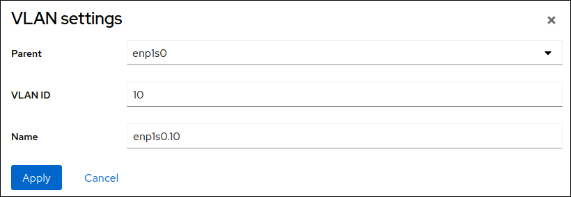
-
Click
.
-
By default, the VLAN device uses a dynamic IP address. If you want to set a static IP address:
-
Click the name of the VLAN device in the
Interfacessection. -
Click
Editnext to the protocol you want to configure. -
Select
Manualnext toAddresses, and enter the IP address, prefix, and default gateway. -
In the
DNSsection, click thebutton, and enter the IP address of the DNS server. Repeat this step to set multiple DNS servers.
-
In the
DNS search domainssection, click thebutton, and enter the search domain.
-
If the interface requires static routes, configure them in the
Routessection.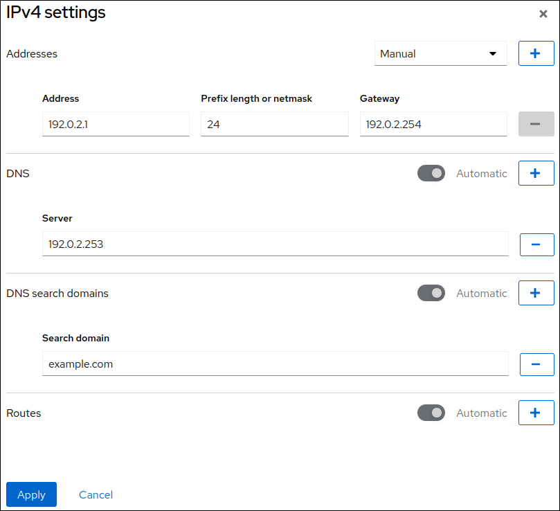
- Click
-
Click the name of the VLAN device in the
Verification
-
Select the
Networkingtab in the navigation on the left side of the screen, and check if there is incoming and outgoing traffic on the interface: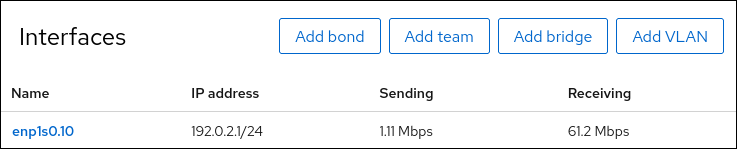
5.3. Configuring VLAN tagging using nmtui
The nmtui application provides a text-based user interface for NetworkManager. You can use nmtui to configure VLAN tagging on a host without a graphical interface.
Note
In nmtui:
- Navigate by using the cursor keys.
-
Press a button by selecting it and hitting
Enter
.
-
Select and deselect checkboxes by using
Space
.
Prerequisites
- The interface you plan to use as a parent to the virtual VLAN interface supports VLAN tags.
-
If you configure the VLAN on top of a bond interface:
- The ports of the bond are up.
-
The bond is not configured with the
fail_over_mac=followoption. A VLAN virtual device cannot change its MAC address to match the parent’s new MAC address. In such a case, the traffic would still be sent with the then incorrect source MAC address. -
The bond is usually not expected to get IP addresses from a DHCP server or IPv6 auto-configuration. Ensure it by setting the
ipv4.method=disableandipv6.method=ignoreoptions while creating the bond. Otherwise, if DHCP or IPv6 auto-configuration fails after some time, the interface might be brought down.
- The switch the host is connected to is configured to support VLAN tags. For details, see the documentation of your switch.
Procedure
-
If you do not know the network device name on which you want configure VLAN tagging, display the available devices:
#
nmcli device status
DEVICE TYPE STATE CONNECTIONenp1s0
ethernet unavailable -- ... -
Start
nmtui:#
nmtui
-
Select
Edit a connection, and pressEnter
.
-
Press the
Addbutton. -
Select
VLANfrom the list of network types, and pressEnter
.
- Optional: Enter a name for the NetworkManager profile to be created.
-
Enter the VLAN device name to be created into the
Devicefield. -
Enter the name of the device on which you want to configure VLAN tagging into the
Parentfield. -
Enter the VLAN ID. The ID must be within the range from
0to4094. -
Depending on your environment, configure the IP address settings in the
IPv4 configurationandIPv6 configurationareas accordingly. For this, press theAutomaticbutton, and select:-
Disabled, if this VLAN device does not require an IP address or you want to use it as a port of other devices. -
Automatic, if a DHCP server dynamically assigns an IP address to the VLAN device. -
Manual, if the network requires static IP address settings. In this case, you must fill further fields:-
Press the
Showbutton next to the protocol you want to configure to display additional fields. -
Press the
Addbutton next toAddresses, and enter the IP address and the subnet mask in Classless Inter-Domain Routing (CIDR) format.If you do not specify a subnet mask, NetworkManager sets a
/32subnet mask for IPv4 addresses and/64for IPv6 addresses. - Enter the address of the default gateway.
-
Press the
Addbutton next toDNS servers, and enter the DNS server address. -
Press the
Addbutton next toSearch domains, and enter the DNS search domain.
-
Press the
Figure 5.1. Example of a VLAN connection with static IP address settings
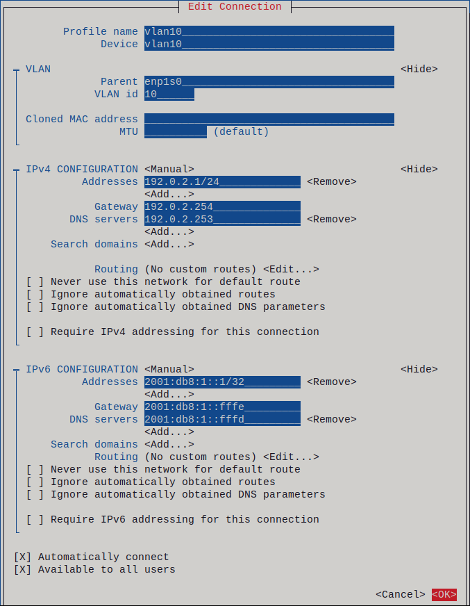
-
-
Press the
OKbutton to create and automatically activate the new connection. -
Press the
Backbutton to return to the main menu. -
Select
Quit, and pressEnter
to close the
nmtuiapplication.
Verification
-
Verify the settings:
#
ip -d addr show
4: vlan10@enp1s0: <BROADCAST,MULTICAST,UP,LOWER_UP> mtu 1500 qdisc noqueue state UP group default qlen 1000 link/ether 52:54:00:72:2f:6e brd ff:ff:ff:ff:ff:ff promiscuity 0 vlan protocol 802.1Q id 10 <REORDER_HDR> numtxqueues 1 numrxqueues 1 gso_max_size 65536 gso_max_segs 65535 inet 192.0.2.1/24 brd 192.0.2.255 scope global noprefixroute vlan10 valid_lft forever preferred_lft forever inet6 2001:db8:1::1/32 scope global noprefixroute valid_lft forever preferred_lft forever inet6 fe80::8dd7:9030:6f8e:89e6/64 scope link noprefixroute valid_lft forever preferred_lft forevervlan10
5.4. Configuring VLAN tagging using nm-connection-editor
You can configure Virtual Local Area Network (VLAN) tagging in a graphical interface using the nm-connection-editor application.
Prerequisites
- The interface you plan to use as a parent to the virtual VLAN interface supports VLAN tags.
-
If you configure the VLAN on top of a bond interface:
- The ports of the bond are up.
-
The bond is not configured with the
fail_over_mac=followoption. A VLAN virtual device cannot change its MAC address to match the parent’s new MAC address. In such a case, the traffic would still be sent with the incorrect source MAC address.
- The switch, the host is connected, to is configured to support VLAN tags. For details, see the documentation of your switch.
Procedure
-
Open a terminal, and enter
nm-connection-editor:$
nm-connection-editor -
Click the
button to add a new connection.
-
Select the
VLANconnection type, and click.
-
On the
VLANtab:- Select the parent interface.
-
Select the VLAN id. Note that the VLAN must be within the range from
0to4094. - By default, the VLAN connection inherits the maximum transmission unit (MTU) from the parent interface. Optionally, set a different MTU value.
-
Optionally, set the name of the VLAN interface and further VLAN-specific options.
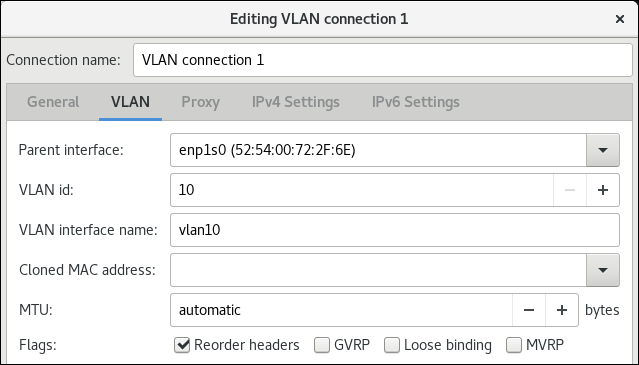
-
Configure the IP settings of the VLAN device. Skip this step if you want to use this VLAN device as a port of other devices.
-
On the
IPv4 Settingstab, configure the IPv4 settings. For example, set a static IPv4 address, network mask, default gateway, and DNS server:

-
On the
IPv6 Settingstab, configure the IPv6 settings. For example, set a static IPv6 address, network mask, default gateway, and DNS server:

-
On the
-
Click
to save the VLAN connection.
-
Close
nm-connection-editor.
Verification steps
-
Verify the settings:
#
ip -d addr show
4: vlan10@enp1s0: <BROADCAST,MULTICAST,UP,LOWER_UP> mtu 1500 qdisc noqueue state UP group default qlen 1000 link/ether 52:54:00:d5:e0:fb brd ff:ff:ff:ff:ff:ff promiscuity 0 vlan protocol 802.1Q id 10 <REORDER_HDR> numtxqueues 1 numrxqueues 1 gso_max_size 65536 gso_max_segs 65535 inet 192.0.2.1/24 brd 192.0.2.255 scope global noprefixroute vlan10 valid_lft forever preferred_lft forever inet6 2001:db8:1::1/32 scope global noprefixroute valid_lft forever preferred_lft forever inet6 fe80::8dd7:9030:6f8e:89e6/64 scope link noprefixroute valid_lft forever preferred_lft forevervlan10
Additional resources
- Configuring NetworkManager to avoid using a specific profile to provide a default gateway
5.5. Configuring VLAN tagging using nmstatectl
You can use the nmstatectl utility to configure Virtual Local Area Network (VLAN) tagging. This example configures a VLAN with ID 10 that uses an Ethernet connection. As the child device, the VLAN connection contains the IP, default gateway, and DNS configurations.
Depending on your environment, adjust the YAML file accordingly. For example, to use a bridge, or bond device in the VLAN, adapt the base-iface attribute and type attributes of the ports you use in the VLAN.
Prerequisites
- To use Ethernet devices as ports in the VLAN, the physical or virtual Ethernet devices must be installed on the server.
-
The
nmstatepackage is installed.
Procedure
-
Create a YAML file, for example
~/create-vlan.yml, with the following contents:--- interfaces: - name: vlan10 type: vlan state: up ipv4: enabled: true address: - ip: 192.0.2.1 prefix-length: 24 dhcp: false ipv6: enabled: true address: - ip: 2001:db8:1::1 prefix-length: 64 autoconf: false dhcp: false vlan: base-iface: enp1s0 id: 10 - name: enp1s0 type: ethernet state: up routes: config: - destination: 0.0.0.0/0 next-hop-address: 192.0.2.254 next-hop-interface: vlan10 - destination: ::/0 next-hop-address: 2001:db8:1::fffe next-hop-interface: vlan10 dns-resolver: config: search: - example.com server: - 192.0.2.200 - 2001:db8:1::ffbb -
Apply the settings to the system:
#
nmstatectl apply ~/create-vlan.yml
Verification steps
-
Display the status of the devices and connections:
#
nmcli device status
DEVICE TYPE STATE CONNECTIONvlan10
vlanconnected
vlan10
-
Display all settings of the connection profile:
#
nmcli connection show
connection.id:vlan10
vlan10
connection.uuid:1722970f-788e-4f81-bd7d-a86bf21c9df5
connection.stable-id: -- connection.type: vlan connection.interface-name:vlan10
... -
Display the connection settings in YAML format:
#
nmstatectl show
vlan0
Additional resources
-
nmstatectl(8)man page -
/usr/share/doc/nmstate/examples/directory
5.6. Configuring VLAN tagging using RHEL System Roles
You can use the network RHEL System Role to configure VLAN tagging. This example adds an Ethernet connection and a VLAN with ID 10 on top of this Ethernet connection. As the child device, the VLAN connection contains the IP, default gateway, and DNS configurations.
Depending on your environment, adjust the play accordingly. For example:
-
To use the VLAN as a port in other connections, such as a bond, omit the
ipattribute, and set the IP configuration in the child configuration. -
To use team, bridge, or bond devices in the VLAN, adapt the
interface_nameandtypeattributes of the ports you use in the VLAN.
Perform this procedure on the Ansible control node.
Prerequisites
- You have prepared the control node and the managed nodes
- You are logged in to the control node as a user who can run playbooks on the managed nodes.
-
The account you use to connect to the managed nodes has
sudopermissions on them. - The hosts or host groups on which you to want run this playbook are listed in the Ansible inventory file.
Procedure
-
Create a playbook file, for example
~/vlan-ethernet.yml, with the following content:--- - name: Configure the network hosts:
managed-node-01.example.com
tasks: - name: Configure a VLAN that uses an Ethernet connection include_role: name: rhel-system-roles.network vars: network_connections: # Add an Ethernet profile for the underlying device of the VLAN - name: enp1s0 type: ethernet interface_name: enp1s0 autoconnect: yes state: up ip: dhcp4: no auto6: no # Define the VLAN profile - name: enp1s0.10 type: vlan ip: address: - "192.0.2.1/24" - "2001:db8:1::1/64" gateway4: 192.0.2.254 gateway6: 2001:db8:1::fffe dns: - 192.0.2.200 - 2001:db8:1::ffbb dns_search: - example.com vlan_id: 10 parent: enp1s0 state: upThe
parentattribute in the VLAN profile configures the VLAN to operate on top of theenp1s0device. -
Run the playbook:
#
ansible-playbook
~/vlan-ethernet.yml
Additional resources
-
/usr/share/ansible/roles/rhel-system-roles.network/README.mdfile
5.7. Additional resources
- VLANs for sysadmins: The basics
Chapter 6. Using a VXLAN to create a virtual layer-2 domain for VMs
A virtual extensible LAN (VXLAN) is a networking protocol that tunnels layer-2 traffic over an IP network using the UDP protocol. For example, certain virtual machines (VMs), that are running on different hosts can communicate over a VXLAN tunnel. The hosts can be in different subnets or even in different data centers around the world. From the perspective of the VMs, other VMs in the same VXLAN are within the same layer-2 domain:
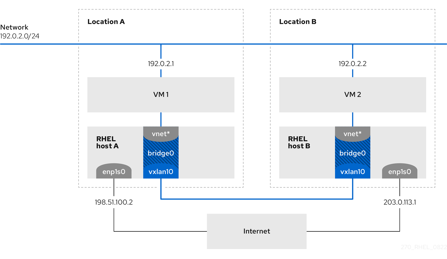
In this example, RHEL-host-A and RHEL-host-B use a bridge, br0, to connect the virtual network of a VM on each host with a VXLAN named vxlan10. Due to this configuration, the VXLAN is invisible to the VMs, and the VMs do not require any special configuration. If you later connect more VMs to the same virtual network, the VMs are automatically members of the same virtual layer-2 domain.
Important
Just as normal layer-2 traffic, data in a VXLAN is not encrypted. For security reasons, use a VXLAN over a VPN or other types of encrypted connections.
6.1. Benefits of VXLANs
A virtual extensible LAN (VXLAN) provides the following major benefits:
- VXLANs use a 24-bit ID. Therefore, you can create up to 16,777,216 isolated networks. For example, a virtual LAN (VLAN), supports only 4,096 isolated networks.
- VXLANs use the IP protocol. This enables you to route the traffic and virtually run systems in different networks and locations within the same layer-2 domain.
- Unlike most tunnel protocols, a VXLAN is not only a point-to-point network. A VXLAN can learn the IP addresses of the other endpoints either dynamically or use statically-configured forwarding entries.
- Certain network cards support UDP tunnel-related offload features.
Additional resources
-
/usr/share/doc/kernel-doc-provided by the<kernel_version>
/Documentation/networking/vxlan.rst
kernel-docpackage
6.2. Configuring the Ethernet interface on the hosts
To connect a RHEL VM host to the Ethernet, create a network connection profile, configure the IP settings, and activate the profile.
Run this procedure on both RHEL hosts, and adjust the IP address configuration accordingly.
Prerequisites
- The host is connected to the Ethernet.
Procedure
-
Add a new Ethernet connection profile to NetworkManager:
#
nmcli connection add con-name
Example
ifnameenp1s0
type ethernet -
Configure the IPv4 settings:
#
nmcli connection modify
Example
ipv4.addresses198.51.100.2/24
ipv4.method manual ipv4.gateway198.51.100.254
ipv4.dns198.51.100.200
ipv4.dns-searchexample.com
Skip this step if the network uses DHCP.
-
Activate the
Exampleconnection:#
nmcli connection up
Example
Verification
-
Display the status of the devices and connections:
#
nmcli device status
DEVICE TYPE STATE CONNECTION enp1s0 ethernet connectedExample
-
Ping a host in a remote network to verify the IP settings:
#
ping
RHEL-host-B.example.com
Note that you cannot ping the other VM host before you have configured the network on that host as well.
Additional resources
-
nm-settings(5)man page
6.3. Creating a network bridge with a VXLAN attached
To make a virtual extensible LAN (VXLAN) invisible to virtual machines (VMs), create a bridge on a host, and attach the VXLAN to the bridge. Use NetworkManager to create both the bridge and the VXLAN. You do not add any traffic access point (TAP) devices of the VMs, typically named vnet* on the host, to the bridge. The libvirtd service adds them dynamically when the VMs start.
Run this procedure on both RHEL hosts, and adjust the IP addresses accordingly.
Procedure
-
Create the bridge
br0:#
nmcli connection add type bridge con-name br0 ifname br0 ipv4.method disabled ipv6.method disabled
This command sets no IPv4 and IPv6 addresses on the bridge device, because this bridge works on layer 2.
-
Create the VXLAN interface and attach it to
br0:#
nmcli connection add type vxlan slave-type bridge con-name
br0-vxlan10
ifnamevxlan10
id10
local198.51.100.2
remote203.0.113.1
masterbr0
This command uses the following settings:
-
id 10: Sets the VXLAN identifier. -
local 198.51.100.2: Sets the source IP address of outgoing packets. -
remote 203.0.113.1: Sets the unicast or multicast IP address to use in outgoing packets when the destination link layer address is not known in the VXLAN device forwarding database. -
master br0: Sets this VXLAN connection to be created as a port in thebr0connection. -
ipv4.method disabledandipv6.method disabled: Disables IPv4 and IPv6 on the bridge.
By default, NetworkManager uses
8472as the destination port. If the destination port is different, additionally, pass thedestination-port <port_number>option to the command. -
-
Activate the
br0connection profile:#
nmcli connection up
br0
-
Open port
8472for incoming UDP connections in the local firewall:#
firewall-cmd --permanent --add-port=8472/udp
#firewall-cmd --reload
Verification
-
Display the forwarding table:
#
bridge fdb show dev
2a:53:bd:d5:b3:0a master br0 permanent 00:00:00:00:00:00 dst 203.0.113.1 self permanent ...vxlan10
Additional resources
-
nm-settings(5)man page
6.4. Creating a virtual network in libvirt with an existing bridge
To enable virtual machines (VM) to use the br0 bridge with the attached virtual extensible LAN (VXLAN), first add a virtual network to the libvirtd service that uses this bridge.
Prerequisites
-
You installed the
libvirtpackage. -
You started and enabled the
libvirtdservice. -
You configured the
br0device with the VXLAN on RHEL.
Procedure
-
Create the
~/vxlan10-bridge.xmlfile with the following content:<network>
<name>vxlan10-bridge</name>
<forward mode="bridge" />
<bridge name="br0" />
</network>
-
Use the
~/vxlan10-bridge.xmlfile to create a new virtual network inlibvirt:#
virsh net-define
~/vxlan10-bridge.xml
-
Remove the
~/vxlan10-bridge.xmlfile:#
rm
~/vxlan10-bridge.xml
-
Start the
vxlan10-bridgevirtual network:#
virsh net-start
vxlan10-bridge
-
Configure the
vxlan10-bridgevirtual network to start automatically when thelibvirtdservice starts:#
virsh net-autostart
vxlan10-bridge
Verification
-
Display the list of virtual networks:
#
virsh net-list
Name State Autostart Persistent ----------------------------------------------------vxlan10-bridge
active yes yes ...
Additional resources
-
virsh(1)man page
6.5. Configuring virtual machines to use VXLAN
To configure a VM to use a bridge device with an attached virtual extensible LAN (VXLAN) on the host, create a new VM that uses the vxlan10-bridge virtual network or update the settings of existing VMs to use this network.
Perform this procedure on the RHEL hosts.
Prerequisites
-
You configured the
vxlan10-bridgevirtual network inlibvirtd.
Procedure
-
To create a new VM and configure it to use the
vxlan10-bridgenetwork, pass the--network network:vxlan10-bridgeoption to thevirt-installcommand when you create the VM:#
virt-install ... --network network:
vxlan10-bridge
-
To change the network settings of an existing VM:
-
Connect the VM’s network interface to the
vxlan10-bridgevirtual network:#
virt-xml
VM_name
--edit --network network=vxlan10-bridge
-
Shut down the VM, and start it again:
#
virsh shutdown
#VM_name
virsh start
VM_name
-
Verification
-
Display the virtual network interfaces of the VM on the host:
#
virsh domiflist
Interface Type Source Model MAC -------------------------------------------------------------------VM_name
vnet1
bridgevxlan10-bridge
virtio52:54:00:c5:98:1c
-
Display the interfaces attached to the
vxlan10-bridgebridge:#
ip link show master vxlan10-bridge
18: vxlan10: <BROADCAST,MULTICAST,UP,LOWER_UP> mtu 1500 qdisc noqueue masterbr0
state UNKNOWN mode DEFAULT group default qlen 1000 link/ether2a:53:bd:d5:b3:0a
brd ff:ff:ff:ff:ff:ff 19: vnet1: <BROADCAST,MULTICAST,UP,LOWER_UP> mtu 1500 qdisc noqueue masterbr0
state UNKNOWN mode DEFAULT group default qlen 1000 link/ether52:54:00:c5:98:1c
brd ff:ff:ff:ff:ff:ffNote that the
libvirtdservice dynamically updates the bridge’s configuration. When you start a VM which uses thevxlan10-bridgenetwork, the correspondingvnet*device on the host appears as a port of the bridge. -
Use address resolution protocol (ARP) requests to verify whether VMs are in the same VXLAN:
- Start two or more VMs in the same VXLAN.
-
Send an ARP request from one VM to the other one:
#
arping -c 1
ARPING192.0.2.2
192.0.2.2
from192.0.2.1
enp1s0
Unicast reply from192.0.2.2
[52:54:00:c5:98:1c
]1.450ms
Sent 1 probe(s) (0 broadcast(s)) Received 1 response(s) (0 request(s), 0 broadcast(s))If the command shows a reply, the VM is in the same layer-2 domain and, in this case in the same VXLAN.
Install the
iputilspackage to use thearpingutility.
Additional resources
-
virt-install(1)man page -
virt-xml(1)man page -
virsh(1)man page -
arping(8)man page
Chapter 7. Configuring a network bridge
A network bridge is a link-layer device which forwards traffic between networks based on a table of MAC addresses. The bridge builds the MAC addresses table by listening to network traffic and thereby learning what hosts are connected to each network. For example, you can use a software bridge on a Red Hat Enterprise Linux host to emulate a hardware bridge or in virtualization environments, to integrate virtual machines (VM) to the same network as the host.
A bridge requires a network device in each network the bridge should connect. When you configure a bridge, the bridge is called controller and the devices it uses ports.
You can create bridges on different types of devices, such as:
- Physical and virtual Ethernet devices
- Network bonds
- Network teams
- VLAN devices
Due to the IEEE 802.11 standard which specifies the use of 3-address frames in Wi-Fi for the efficient use of airtime, you cannot configure a bridge over Wi-Fi networks operating in Ad-Hoc or Infrastructure modes.
7.1. Configuring a network bridge using nmcli commands
To configure a network bridge on the command line, use the nmcli utility.
Prerequisites
- Two or more physical or virtual network devices are installed on the server.
- To use Ethernet devices as ports of the bridge, the physical or virtual Ethernet devices must be installed on the server.
-
To use team, bond, or VLAN devices as ports of the bridge, you can either create these devices while you create the bridge or you can create them in advance as described in:
- Configuring a network team using nmcli commands
- Configuring a network bond using nmcli commands
- Configuring VLAN tagging using nmcli commands
Procedure
-
Create a bridge interface:
#
nmcli connection add type bridge con-name
bridge0
ifnamebridge0
This command creates a bridge named
bridge0, enter: -
Display the network interfaces, and note the names of the interfaces you want to add to the bridge:
# nmcli device status
DEVICE  TYPE      STATE         CONNECTION
enp7s0  ethernet  disconnected  --
enp8s0  ethernet  disconnected  --
bond0   bond      connected     bond0
bond1   bond      connected     bond1
...
In this example:
-
enp7s0andenp8s0are not configured. To use these devices as ports, add connection profiles in the next step. -
bond0andbond1have existing connection profiles. To use these devices as ports, modify their profiles in the next step.
-
-
Assign the interfaces to the bridge.
-
If the interfaces you want to assign to the bridge are not configured, create new connection profiles for them:
#
nmcli connection add type ethernet slave-type bridge con-name
#bridge0-port1
ifname enp7s0 master bridge0nmcli connection add type ethernet slave-type bridge con-name
bridge0-port2
ifname enp8s0 master bridge0These commands create profiles for
enp7s0andenp8s0, and add them to thebridge0connection. -
If you want to assign an existing connection profile to the bridge:
-
Set the
masterparameter of these connections tobridge0:#
nmcli connection modify
#bond0
master bridge0nmcli connection modify
bond1
master bridge0These commands assign the existing connection profiles named
bond0andbond1to thebridge0connection. -
Reactivate the connections:
#
nmcli connection up
#bond0
nmcli connection up
bond1
-
-
-
Configure the IPv4 settings:
-
To use this bridge device as a port of other devices, enter:
#
nmcli connection modify bridge0 ipv4.method disabled
- To use DHCP, no action is required.
-
To set a static IPv4 address, network mask, default gateway, and DNS server to the
bridge0connection, enter:#
nmcli connection modify bridge0 ipv4.addresses '
#192.0.2.1/24
'nmcli connection modify bridge0 ipv4.gateway '
#192.0.2.254
'nmcli connection modify bridge0 ipv4.dns '
#192.0.2.253
'nmcli connection modify bridge0 ipv4.dns-search '
#example.com
'nmcli connection modify bridge0 ipv4.method manual
-
-
Configure the IPv6 settings:
-
To use this bridge device as a port of other devices, enter:
#
nmcli connection modify bridge0 ipv6.method disabled
- To use DHCP, no action is required.
-
To set a static IPv6 address, network mask, default gateway, and DNS server to the
bridge0connection, enter:#
nmcli connection modify bridge0 ipv6.addresses '
#2001:db8:1::1/64
'nmcli connection modify bridge0 ipv6.gateway '
#2001:db8:1::fffe
'nmcli connection modify bridge0 ipv6.dns '
#2001:db8:1::fffd
'nmcli connection modify bridge0 ipv6.dns-search '
#example.com
'nmcli connection modify bridge0 ipv6.method manual
-
-
Optional: Configure further properties of the bridge. For example, to set the Spanning Tree Protocol (STP) priority of
bridge0to16384, enter:#
nmcli connection modify bridge0 bridge.priority '16384'
By default, STP is enabled.
-
Activate the connection:
#
nmcli connection up bridge0
-
Verify that the ports are connected, and the
CONNECTIONcolumn displays the port’s connection name:#
nmcli device
DEVICE TYPE STATE CONNECTION ... enp7s0 ethernet connected bridge0-port1 enp8s0 ethernet connected bridge0-port2When you activate any port of the connection, NetworkManager also activates the bridge, but not the other ports of it. You can configure that Red Hat Enterprise Linux enables all ports automatically when the bridge is enabled:
-
Enable the
connection.autoconnect-slavesparameter of the bridge connection:#
nmcli connection modify bridge0 connection.autoconnect-slaves 1
-
Reactivate the bridge:
#
nmcli connection up bridge0
-
Verification steps
-
Use the
iputility to display the link status of Ethernet devices that are ports of a specific bridge:#
ip link show master
3: enp7s0: <BROADCAST,MULTICAST,UP,LOWER_UP> mtu 1500 qdisc fq_codel master bridge0 state UP mode DEFAULT group default qlen 1000 link/ether 52:54:00:62:61:0e brd ff:ff:ff:ff:ff:ff 4: enp8s0: <BROADCAST,MULTICAST,UP,LOWER_UP> mtu 1500 qdisc fq_codel master bridge0 state UP mode DEFAULT group default qlen 1000 link/ether 52:54:00:9e:f1:ce brd ff:ff:ff:ff:ff:ffbridge0
-
Use the
bridgeutility to display the status of Ethernet devices that are ports of any bridge device:#
bridge link show
3: enp7s0: <BROADCAST,MULTICAST,UP,LOWER_UP> mtu 1500 master bridge0 state forwarding priority 32 cost 100 4: enp8s0: <BROADCAST,MULTICAST,UP,LOWER_UP> mtu 1500 master bridge0 state listening priority 32 cost 100 5: enp9s0: <BROADCAST,MULTICAST,UP,LOWER_UP> mtu 1500 master bridge1 state forwarding priority 32 cost 100 6: enp11s0: <BROADCAST,MULTICAST,UP,LOWER_UP> mtu 1500 master bridge1 state blocking priority 32 cost 100 ...To display the status for a specific Ethernet device, use the
bridge link show dev ethernet_device_namecommand.
Additional resources
- Configuring NetworkManager to avoid using a specific profile to provide a default gateway
-
nm-settings(5)man page -
bridge(8)man page - NetworkManager duplicates a connection after restart of NetworkManager service
- How to configure bridge with vlan information?
7.2. Configuring a network bridge using the RHEL web console
Use the RHEL web console to configure a network bridge if you prefer to manage network settings using a web browser-based interface.
Prerequisites
- Two or more physical or virtual network devices are installed on the server.
- To use Ethernet devices as ports of the bridge, the physical or virtual Ethernet devices must be installed on the server.
-
To use team, bond, or VLAN devices as ports of the bridge, you can either create these devices while you create the bridge or you can create them in advance as described in:
- Configuring a network team using the RHEL web console
- Configuring a network bond using the RHEL web console
- Configuring VLAN tagging using the RHEL web console
Procedure
-
Select the
Networkingtab in the navigation on the left side of the screen. -
Click
in the
Interfacessection. - Enter the name of the bridge device you want to create.
- Select the interfaces that should be ports of the bridge.
-
Optional: Enable the
Spanning tree protocol (STP)feature to avoid bridge loops and broadcast radiation.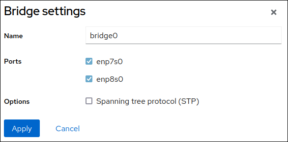
-
Click
.
-
By default, the bridge uses a dynamic IP address. If you want to set a static IP address:
-
Click the name of the bridge in the
Interfacessection. -
Click
Editnext to the protocol you want to configure. -
Select
Manualnext toAddresses, and enter the IP address, prefix, and default gateway. -
In the
DNSsection, click thebutton, and enter the IP address of the DNS server. Repeat this step to set multiple DNS servers.
-
In the
DNS search domainssection, click thebutton, and enter the search domain.
-
If the interface requires static routes, configure them in the
Routessection. - Click
-
Click the name of the bridge in the
Verification
-
Select the
Networkingtab in the navigation on the left side of the screen, and check if there is incoming and outgoing traffic on the interface:
7.3. Configuring a network bridge using nmtui
The nmtui application provides a text-based user interface for NetworkManager. You can use nmtui to configure a network bridge on a host without a graphical interface.
Note
In nmtui:
- Navigate by using the cursor keys.
-
Press a button by selecting it and hitting
Enter
.
-
Select and deselect checkboxes by using
Space
.
Prerequisites
- Two or more physical or virtual network devices are installed on the server.
- To use Ethernet devices as ports of the bridge, the physical or virtual Ethernet devices must be installed on the server.
Procedure
-
If you do not know the network device names on which you want configure a network bridge, display the available devices:
#
nmcli device status
DEVICE TYPE STATE CONNECTIONenp7s0
ethernet unavailable --enp8s0
ethernet unavailable -- ... -
Start
nmtui:#
nmtui
-
Select
Edit a connection, and pressEnter
.
-
Press the
Addbutton. -
Select
Bridgefrom the list of network types, and pressEnter
.
- Optional: Enter a name for the NetworkManager profile to be created.
-
Enter the bridge device name to be created into the
Devicefield. -
Add ports to the bridge to be created:
-
Press the
Addbutton next to theSlaveslist. -
Select the type of the interface you want to add as port to the bridge, for example,
Ethernet. - Optional: Enter a name for the NetworkManager profile to be created for this bridge port.
-
Enter the port’s device name into the
Devicefield. -
Press the
OKbutton to return to the window with the bridge settings.Figure 7.1. Adding an Ethernet device as port to a bridge
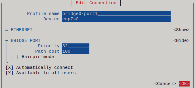
- Repeat these steps to add more ports to the bridge.
-
Press the
-
Depending on your environment, configure the IP address settings in the
IPv4 configurationandIPv6 configurationareas accordingly. For this, press theAutomaticbutton, and select:-
Disabled, if the bridge does not require an IP address. -
Automatic, if a DHCP server dynamically assigns an IP address to the bridge. -
Manual, if the network requires static IP address settings. In this case, you must fill further fields:-
Press the
Showbutton next to the protocol you want to configure to display additional fields. -
Press the
Addbutton next toAddresses, and enter the IP address and the subnet mask in Classless Inter-Domain Routing (CIDR) format.If you do not specify a subnet mask, NetworkManager sets a
/32subnet mask for IPv4 addresses and/64for IPv6 addresses. - Enter the address of the default gateway.
-
Press the
Addbutton next toDNS servers, and enter the DNS server address. -
Press the
Addbutton next toSearch domains, and enter the DNS search domain.
-
Press the
Figure 7.2. Example of a bridge connection without IP address settings
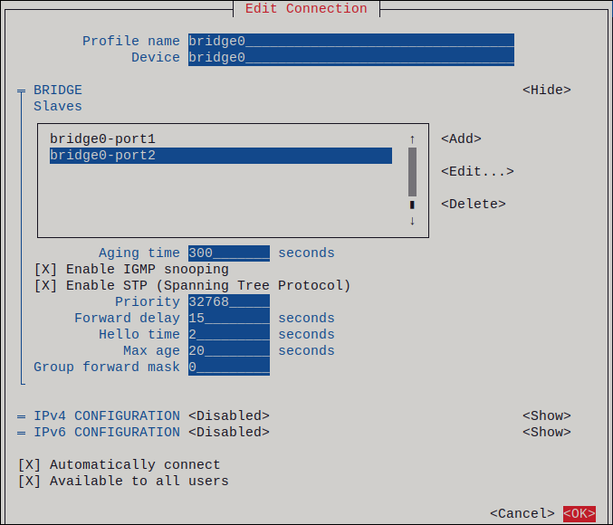
-
-
Press the
OKbutton to create and automatically activate the new connection. -
Press the
Backbutton to return to the main menu. -
Select
Quit, and pressEnter
to close the
nmtuiapplication.
Verification
-
Use the
iputility to display the link status of Ethernet devices that are ports of a specific bridge:#
ip link show master
3: enp7s0: <BROADCAST,MULTICAST,UP,LOWER_UP> mtu 1500 qdisc fq_codel master bridge0 state UP mode DEFAULT group default qlen 1000 link/ether 52:54:00:62:61:0e brd ff:ff:ff:ff:ff:ff 4: enp8s0: <BROADCAST,MULTICAST,UP,LOWER_UP> mtu 1500 qdisc fq_codel master bridge0 state UP mode DEFAULT group default qlen 1000 link/ether 52:54:00:9e:f1:ce brd ff:ff:ff:ff:ff:ffbridge0
-
Use the
bridgeutility to display the status of Ethernet devices that are ports of any bridge device:#
bridge link show
3: enp7s0: <BROADCAST,MULTICAST,UP,LOWER_UP> mtu 1500 master bridge0 state forwarding priority 32 cost 100 4: enp8s0: <BROADCAST,MULTICAST,UP,LOWER_UP> mtu 1500 master bridge0 state listening priority 32 cost 100 ...To display the status for a specific Ethernet device, use the
bridge link show dev ethernet_device_namecommand.
7.4. Configuring a network bridge using nm-connection-editor
If you use Red Hat Enterprise Linux with a graphical interface, you can configure network bridges using the nm-connection-editor application.
Note that nm-connection-editor can add only new ports to a bridge. To use an existing connection profile as a port, create the bridge using the nmcli utility as described in Configuring a network bridge using nmcli commands.
Prerequisites
- Two or more physical or virtual network devices are installed on the server.
- To use Ethernet devices as ports of the bridge, the physical or virtual Ethernet devices must be installed on the server.
- To use team, bond, or VLAN devices as ports of the bridge, ensure that these devices are not already configured.
Procedure
-
Open a terminal, and enter
nm-connection-editor:$
nm-connection-editor -
Click the
button to add a new connection.
-
Select the
Bridgeconnection type, and click.
-
In the
Bridgetab:-
Optional: Set the name of the bridge interface in the
Interface namefield. -
Click the Add button to create a new connection profile for a network interface and adding the profile as a port to the bridge.
-
Select the connection type of the interface. For example, select
Ethernetfor a wired connection. - Optionally, set a connection name for the port device.
-
If you create a connection profile for an Ethernet device, open the
Ethernettab, and select in theDevicefield the network interface you want to add as a port to the bridge. If you selected a different device type, configure it accordingly. -
Click
.
-
Select the connection type of the interface. For example, select
-
Repeat the previous step for each interface you want to add to the bridge.
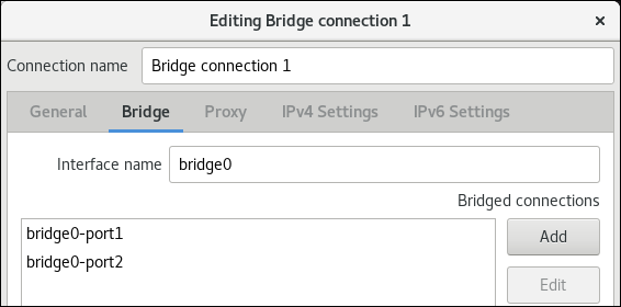
-
Optional: Set the name of the bridge interface in the
- Optional: Configure further bridge settings, such as Spanning Tree Protocol (STP) options.
-
Configure the IP settings of the bridge. Skip this step if you want to use this bridge as a port of other devices.
-
In the
IPv4 Settingstab, configure the IPv4 settings. For example, set a static IPv4 address, network mask, default gateway, DNS server, and DNS search domain:
-
In the
IPv6 Settingstab, configure the IPv6 settings. For example, set a static IPv6 address, network mask, default gateway, DNS server, and DNS search domain: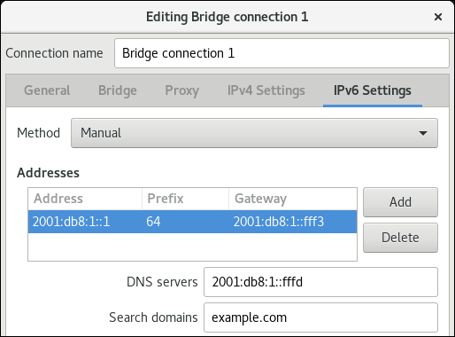
-
- Save the bridge connection.
-
Close
nm-connection-editor.
Verification steps
-
Use the
iputility to display the link status of Ethernet devices that are ports of a specific bridge.#
ip link show master
3: enp7s0: <BROADCAST,MULTICAST,UP,LOWER_UP> mtu 1500 qdisc fq_codel master bridge0 state UP mode DEFAULT group default qlen 1000 link/ether 52:54:00:62:61:0e brd ff:ff:ff:ff:ff:ff 4: enp8s0: <BROADCAST,MULTICAST,UP,LOWER_UP> mtu 1500 qdisc fq_codel master bridge0 state UP mode DEFAULT group default qlen 1000 link/ether 52:54:00:9e:f1:ce brd ff:ff:ff:ff:ff:ffbridge0
-
Use the
bridgeutility to display the status of Ethernet devices that are ports in any bridge device:#
bridge link show
3: enp7s0: <BROADCAST,MULTICAST,UP,LOWER_UP> mtu 1500 master bridge0 state forwarding priority 32 cost 100 4: enp8s0: <BROADCAST,MULTICAST,UP,LOWER_UP> mtu 1500 master bridge0 state listening priority 32 cost 100 5: enp9s0: <BROADCAST,MULTICAST,UP,LOWER_UP> mtu 1500 master bridge1 state forwarding priority 32 cost 100 6: enp11s0: <BROADCAST,MULTICAST,UP,LOWER_UP> mtu 1500 master bridge1 state blocking priority 32 cost 100 ...To display the status for a specific Ethernet device, use the
bridge link show dev ethernet_device_namecommand.
Additional resources
- Configuring a network bond using nm-connection-editor
- Configuring a network team using nm-connection-editor
- Configuring VLAN tagging using nm-connection-editor
- Configuring NetworkManager to avoid using a specific profile to provide a default gateway
- How to configure bridge with vlan information?
7.5. Configuring a network bridge using nmstatectl
To configure a network bridge using the Nmstate API, use the nmstatectl utility.
For example, the procedure below creates a bridge in NetworkManager with the following settings:
-
Network interfaces in the bridge:
enp1s0andenp7s0 - Spanning Tree Protocol (STP): Enabled
-
Static IPv4 address:
192.0.2.1with the/24subnet mask -
Static IPv6 address:
2001:db8:1::1with the/64subnet mask -
IPv4 default gateway:
192.0.2.254 -
IPv6 default gateway:
2001:db8:1::fffe -
IPv4 DNS server:
192.0.2.200 -
IPv6 DNS server:
2001:db8:1::ffbb -
DNS search domain:
example.com
Prerequisites
- Two or more physical or virtual network devices are installed on the server.
- To use Ethernet devices as ports in the bridge, the physical or virtual Ethernet devices must be installed on the server.
-
To use team, bond, or VLAN devices as ports in the bridge, set the interface name in the
portlist, and define the corresponding interfaces. -
The
nmstatepackage is installed.
Procedure
-
Create a YAML file, for example
~/create-bridge.yml, with the following contents:--- interfaces: - name: bridge0 type: linux-bridge state: up ipv4: enabled: true address: - ip: 192.0.2.1 prefix-length: 24 dhcp: false ipv6: enabled: true address: - ip: 2001:db8:1::1 prefix-length: 64 autoconf: false dhcp: false bridge: options: stp: enabled: true port: - name: enp1s0 - name: enp7s0 - name: enp1s0 type: ethernet state: up - name: enp7s0 type: ethernet state: up routes: config: - destination: 0.0.0.0/0 next-hop-address: 192.0.2.254 next-hop-interface: bridge0 - destination: ::/0 next-hop-address: 2001:db8:1::fffe next-hop-interface: bridge0 dns-resolver: config: search: - example.com server: - 192.0.2.200 - 2001:db8:1::ffbb -
Apply the settings to the system:
#
nmstatectl apply ~/create-bridge.yml
Verification steps
-
Display the status of the devices and connections:
#
nmcli device status
DEVICE TYPE STATE CONNECTIONbridge0
bridgeconnected
bridge0
-
Display all settings of the connection profile:
#
nmcli connection show
connection.id:bridge0
bridge0
connection.uuid:e2cc9206-75a2-4622-89cf-1252926060a9
connection.stable-id: -- connection.type: bridge connection.interface-name:bridge0
... -
Display the connection settings in YAML format:
#
nmstatectl show
bridge0
Additional resources
-
nmstatectl(8)man page -
/usr/share/doc/nmstate/examples/directory - How to configure bridge with vlan information?
7.6. Configuring a network bridge using RHEL System Roles
You can use the network RHEL System Role to configure a Linux bridge. For example, use it to configure a network bridge that uses two Ethernet devices, and sets IPv4 and IPv6 addresses, default gateways, and DNS configuration.
Note
Set the IP configuration on the bridge and not on the ports of the Linux bridge.
Perform this procedure on the Ansible control node.
Prerequisites
- You have prepared the control node and the managed nodes
- You are logged in to the control node as a user who can run playbooks on the managed nodes.
-
The account you use to connect to the managed nodes has
sudopermissions on them. - The hosts or host groups on which you want to run this playbook are listed in the Ansible inventory file.
- Two or more physical or virtual network devices are installed on the server.
Procedure
-
Create a playbook file, for example
~/bridge-ethernet.yml, with the following content:--- - name: Configure the network hosts:
managed-node-01.example.com
tasks: - name: Configure a network bridge that uses two Ethernet ports include_role: name: rhel-system-roles.network vars: network_connections: # Define the bridge profile - name: bridge0 type: bridge interface_name: bridge0 ip: address: - "192.0.2.1/24" - "2001:db8:1::1/64" gateway4: 192.0.2.254 gateway6: 2001:db8:1::fffe dns: - 192.0.2.200 - 2001:db8:1::ffbb dns_search: - example.com state: up # Add an Ethernet profile to the bridge - name: bridge0-port1 interface_name: enp7s0 type: ethernet controller: bridge0 port_type: bridge state: up # Add a second Ethernet profile to the bridge - name: bridge0-port2 interface_name: enp8s0 type: ethernet controller: bridge0 port_type: bridge state: up -
Run the playbook:
#
ansible-playbook
~/bridge-ethernet.yml
Additional resources
-
/usr/share/ansible/roles/rhel-system-roles.network/README.mdfile
Chapter 9. Configuring network bonding
A network bond is a method to combine or aggregate physical and virtual network interfaces to provide a logical interface with higher throughput or redundancy. In a bond, the kernel handles all operations exclusively. You can create bonds on different types of devices, such as Ethernet devices or VLANs.
Red Hat Enterprise Linux provides administrators different options to configure team devices. For example:
-
Use
nmclito configure bond connections using the command line. - Use the RHEL web console to configure bond connections using a web browser.
-
Use
nmtuito configure bond connections in a text-based user interface. -
Use the
nm-connection-editorapplication to configure bond connections in a graphical interface. -
Use
nmstatectlto configure bond connections through the Nmstate API. - Use RHEL System Roles to automate the bond configuration on one or multiple hosts.
9.1. Understanding network bonding
Network bonding is a method to combine or aggregate network interfaces to provide a logical interface with higher throughput or redundancy.
The active-backup, balance-tlb, and balance-alb modes do not require any specific configuration of the network switch. However, other bonding modes require configuring the switch to aggregate the links. For example, Cisco switches requires EtherChannel for modes 0, 2, and 3, but for mode 4, the Link Aggregation Control Protocol (LACP) and EtherChannel are required.
For further details, see the documentation of your switch and Linux Ethernet Bonding Driver HOWTO.
Important
Certain network bonding features, such as the fail-over mechanism, do not support direct cable connections without a network switch. For further details, see the Is bonding supported with direct connection using crossover cables? KCS solution.
9.2. Understanding the default behavior of controller and port interfaces
Consider the following default behavior of, when managing or troubleshooting team or bond port interfaces using the NetworkManager service:
- Starting the controller interface does not automatically start the port interfaces.
- Starting a port interface always starts the controller interface.
- Stopping the controller interface also stops the port interface.
- A controller without ports can start static IP connections.
- A controller without ports waits for ports when starting DHCP connections.
- A controller with a DHCP connection waiting for ports completes when you add a port with a carrier.
- A controller with a DHCP connection waiting for ports continues waiting when you add a port without carrier.
9.3. Comparison of network teaming and bonding features
Learn about the features supported in network teams and network bonds:
FeatureNetwork bondNetwork team
Broadcast Tx policy
Yes
Yes
Round-robin Tx policy
Yes
Yes
Active-backup Tx policy
Yes
Yes
LACP (802.3ad) support
Yes (active only)
Yes
Hash-based Tx policy
Yes
Yes
User can set hash function
No
Yes
Tx load-balancing support (TLB)
Yes
Yes
LACP hash port select
Yes
Yes
Load-balancing for LACP support
No
Yes
Ethtool link monitoring
Yes
Yes
ARP link monitoring
Yes
Yes
NS/NA (IPv6) link monitoring
No
Yes
Ports up/down delays
Yes
Yes
Port priorities and stickiness (“primary” option enhancement)
No
Yes
Separate per-port link monitoring setup
No
Yes
Multiple link monitoring setup
Limited
Yes
Lockless Tx/Rx path
No (rwlock)
Yes (RCU)
VLAN support
Yes
Yes
User-space runtime control
Limited
Yes
Logic in user-space
No
Yes
Extensibility
Hard
Easy
Modular design
No
Yes
Performance overhead
Low
Very low
D-Bus interface
No
Yes
Multiple device stacking
Yes
Yes
Zero config using LLDP
No
(in planning)
NetworkManager support
Yes
Yes
9.4. Upstream Switch Configuration Depending on the Bonding Modes
Apply the following settings to the upstream switch depending on the bonding mode:
Bonding modeConfiguration on the switch
0 – balance-rr
Requires static Etherchannel enabled (not LACP-negotiated)
1 – active-backup
Requires autonomous ports
2 – balance-xor
Requires static Etherchannel enabled (not LACP-negotiated)
3 – broadcast
Requires static Etherchannel enabled (not LACP-negotiated)
4 – 802.3ad
Requires LACP-negotiated Etherchannel enabled
5 – balance-tlb
Requires autonomous ports
6 – balance-alb
Requires autonomous ports
For configuring these settings on your switch, see the documentation of the switch.
9.5. Configuring a network bond using nmcli commands
To configure a network bond on the command line, use the nmcli utility.
Prerequisites
- Two or more physical or virtual network devices are installed on the server.
- To use Ethernet devices as ports of the bond, the physical or virtual Ethernet devices must be installed on the server.
-
To use team, bridge, or VLAN devices as ports of the bond, you can either create these devices while you create the bond or you can create them in advance as described in:
- Configuring a network team using nmcli commands
- Configuring a network bridge using nmcli commands
- Configuring VLAN tagging using nmcli commands
Procedure
-
Create a bond interface:
#
nmcli connection add type bond con-name
bond0
ifnamebond0
bond.options "mode=active-backup
"This command creates a bond named
bond0that uses theactive-backupmode.To additionally set a Media Independent Interface (MII) monitoring interval, add the
miimon=intervaloption to thebond.optionsproperty. For example, to use the same command but, additionally, set the MII monitoring interval to1000milliseconds (1 second), enter:#
nmcli connection add type bond con-name bond0 ifname bond0 bond.options "mode=
active-backup
,miimon=1000
" -
Display the network interfaces, and note names of interfaces you plan to add to the bond:
# nmcli device status
DEVICE   TYPE      STATE         CONNECTION
enp7s0   ethernet  disconnected  --
enp8s0   ethernet  disconnected  --
bridge0  bridge    connected     bridge0
bridge1  bridge    connected     bridge1
...
In this example:
-
enp7s0andenp8s0are not configured. To use these devices as ports, add connection profiles in the next step. -
bridge0andbridge1have existing connection profiles. To use these devices as ports, modify their profiles in the next step.
-
-
Assign interfaces to the bond:
-
If the interfaces you want to assign to the bond are not configured, create new connection profiles for them:
#
nmcli connection add type ethernet slave-type bond con-name
#bond0-port1
ifnameenp7s0
master bond0nmcli connection add type ethernet slave-type bond con-name
bond0-port2
ifnameenp8s0
master bond0These commands create profiles for
enp7s0andenp8s0, and add them to thebond0connection. -
To assign an existing connection profile to the bond:
-
Set the
masterparameter of these connections tobond0:#
nmcli connection modify
#bridge0
master bond0nmcli connection modify
bridge1
master bond0These commands assign the existing connection profiles named
bridge0andbridge1to thebond0connection. -
Reactivate the connections:
#
nmcli connection up
#bridge0
nmcli connection up
bridge1
-
-
Configure the IPv4 settings:
-
To use this bond device as a port of other devices, enter:
#
nmcli connection modify bond0 ipv4.method disabled
- To use DHCP, no action is required.
-
To set a static IPv4 address, network mask, default gateway, and DNS server to the
bond0connection, enter:#
nmcli connection modify bond0 ipv4.addresses '
#192.0.2.1/24
'nmcli connection modify bond0 ipv4.gateway '
#192.0.2.254
'nmcli connection modify bond0 ipv4.dns '
#192.0.2.253
'nmcli connection modify bond0 ipv4.dns-search '
#example.com
'nmcli connection modify bond0 ipv4.method manual
-
-
Configure the IPv6 settings:
-
To use this bond device as a port of other devices, enter:
#
nmcli connection modify bond0 ipv6.method disabled
- To use DHCP, no action is required.
-
To set a static IPv6 address, network mask, default gateway, and DNS server to the
bond0connection, enter:#
nmcli connection modify bond0 ipv6.addresses '
#2001:db8:1::1/64
'nmcli connection modify bond0 ipv6.gateway '
#2001:db8:1::fffe
'nmcli connection modify bond0 ipv6.dns '
#2001:db8:1::fffd
'nmcli connection modify bond0 ipv6.dns-search '
#example.com
'nmcli connection modify bond0 ipv6.method manual
-
-
-
Activate the connection:
#
nmcli connection up bond0
-
Verify that the ports are connected, and the
CONNECTIONcolumn displays the port’s connection name:#
nmcli device
DEVICE TYPE STATE CONNECTION ... enp7s0 ethernet connected bond0-port1 enp8s0 ethernet connected bond0-port2When you activate any port of the connection, NetworkManager also activates the bond, but not the other ports of it. You can configure that Red Hat Enterprise Linux enables all ports automatically when the bond is enabled:
-
Enable the
connection.autoconnect-slavesparameter of the bond’s connection:#
nmcli connection modify bond0 connection.autoconnect-slaves 1
-
Reactivate the bridge:
#
nmcli connection up bond0
-
Verification steps
-
Temporarily remove the network cable from the host.
Note that there is no method to properly test link failure events using software utilities. Tools that deactivate connections, such as
nmcli, show only the bonding driver’s ability to handle port configuration changes and not actual link failure events. -
Display the status of the bond:
#
cat /proc/net/bonding/
bond0
Additional resources
- Configuring NetworkManager to avoid using a specific profile to provide a default gateway
- Network bonding documentation
9.6. Configuring a network bond using the RHEL web console
Use the RHEL web console to configure a network bond if you prefer to manage network settings using a web browser-based interface.
Prerequisites
- You are logged in to the RHEL web console.
- Two or more physical or virtual network devices are installed on the server.
- To use Ethernet devices as members of the bond, the physical or virtual Ethernet devices must be installed on the server.
-
To use team, bridge, or VLAN devices as members of the bond, create them in advance as described in:
- Configuring a network team using the RHEL web console
- Configuring a network bridge using the RHEL web console
- Configuring VLAN tagging using the RHEL web console
Procedure
-
Select the
Networkingtab in the navigation on the left side of the screen. -
Click
in the
Interfacessection. - Enter the name of the bond device you want to create.
- Select the interfaces that should be members of the bond.
-
Select the mode of the bond.
If you select
Active backup, the web console shows the additional fieldPrimaryin which you can select the preferred active device. -
Set the link monitoring mode. For example, when you use the
Adaptive load balancingmode, set it toARP. -
Optional: Adjust the monitoring interval, link up delay, and link down delay settings. Typically, you only change the defaults for troubleshooting purposes.
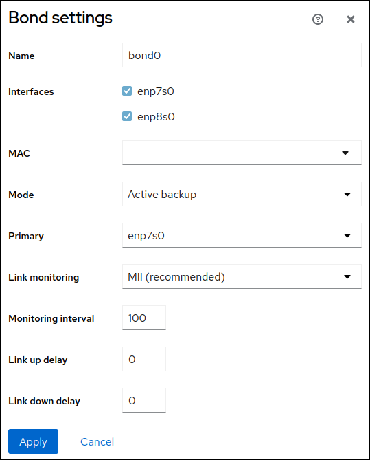
-
Click
.
-
By default, the bond uses a dynamic IP address. If you want to set a static IP address:
-
Click the name of the bond in the
Interfacessection. -
Click
Editnext to the protocol you want to configure. -
Select
Manualnext toAddresses, and enter the IP address, prefix, and default gateway. -
In the
DNSsection, click thebutton, and enter the IP address of the DNS server. Repeat this step to set multiple DNS servers.
-
In the
DNS search domainssection, click thebutton, and enter the search domain.
-
If the interface requires static routes, configure them in the
Routessection. - Click
-
Click the name of the bond in the
Verification
-
Select the
Networkingtab in the navigation on the left side of the screen, and check if there is incoming and outgoing traffic on the interface:
-
Temporarily remove the network cable from the host.
Note that there is no method to properly test link failure events using software utilities. Tools that deactivate connections, such as the web console, show only the bonding driver’s ability to handle member configuration changes and not actual link failure events.
-
Display the status of the bond:
#
cat /proc/net/bonding/
bond0
9.7. Configuring a network bond using nmtui
The nmtui application provides a text-based user interface for NetworkManager. You can use nmtui to configure a network bond on a host without a graphical interface.
Note
In nmtui:
- Navigate by using the cursor keys.
-
Press a button by selecting it and hitting
Enter
.
-
Select and deselect checkboxes by using
Space
.
Prerequisites
- Two or more physical or virtual network devices are installed on the server.
- To use Ethernet devices as ports of the bond, the physical or virtual Ethernet devices must be installed on the server.
Procedure
-
If you do not know the network device names on which you want configure a network bond, display the available devices:
#
nmcli device status
DEVICE TYPE STATE CONNECTIONenp7s0
ethernet unavailable --enp8s0
ethernet unavailable -- ... -
Start
nmtui:#
nmtui
-
Select
Edit a connection, and pressEnter
.
-
Press the
Addbutton. -
Select
Bondfrom the list of network types, and pressEnter
.
- Optional: Enter a name for the NetworkManager profile to be created.
-
Enter the bond device name to be created into the
Devicefield. -
Add ports to the bond to be created:
-
Press the
Addbutton next to theSlaveslist. -
Select the type of the interface you want to add as port to the bond, for example,
Ethernet. - Optional: Enter a name for the NetworkManager profile to be created for this bond port.
-
Enter the port’s device name into the
Devicefield. -
Press the
OKbutton to return to the window with the bond settings.Figure 9.1. Adding an Ethernet device as port to a bond
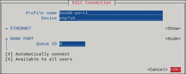
- Repeat these steps to add more ports to the bond.
-
Press the
-
Set the bond mode. Depending on the value you set,
nmtuidisplays additional fields for settings that are related to the selected mode. -
Depending on your environment, configure the IP address settings in the
IPv4 configurationandIPv6 configurationareas accordingly. For this, press theAutomaticbutton, and select:-
Disabled, if the bond does not require an IP address. -
Automatic, if a DHCP server dynamically assigns an IP address to the bond. -
Manual, if the network requires static IP address settings. In this case, you must fill further fields:-
Press the
Showbutton next to the protocol you want to configure to display additional fields. -
Press the
Addbutton next toAddresses, and enter the IP address and the subnet mask in Classless Inter-Domain Routing (CIDR) format.If you do not specify a subnet mask, NetworkManager sets a
/32subnet mask for IPv4 addresses and/64for IPv6 addresses. - Enter the address of the default gateway.
-
Press the
Addbutton next toDNS servers, and enter the DNS server address. -
Press the
Addbutton next toSearch domains, and enter the DNS search domain.
-
Press the
Figure 9.2. Example of a bond connection with static IP address settings
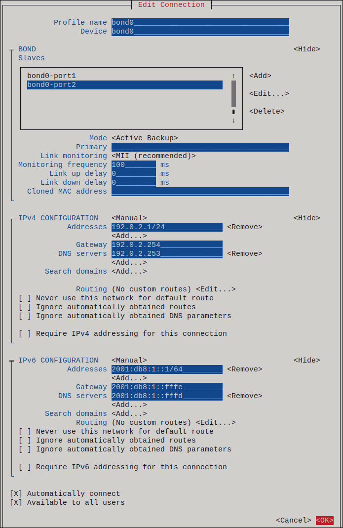
-
-
Press the
OKbutton to create and automatically activate the new connection. -
Press the
Backbutton to return to the main menu. -
Select
Quit, and pressEnter
to close the
nmtuiapplication.
Verification
-
Temporarily remove the network cable from the host.
Note that there is no method to properly test link failure events using software utilities. Tools that deactivate connections, such as
nmcli, show only the bonding driver’s ability to handle port configuration changes and not actual link failure events. -
Display the status of the bond:
#
cat /proc/net/bonding/
bond0
9.8. Configuring a network bond using nm-connection-editor
If you use Red Hat Enterprise Linux with a graphical interface, you can configure network bonds using the nm-connection-editor application.
Note that nm-connection-editor can add only new ports to a bond. To use an existing connection profile as a port, create the bond using the nmcli utility as described in Configuring a network bond using nmcli commands.
Prerequisites
- Two or more physical or virtual network devices are installed on the server.
- To use Ethernet devices as ports of the bond, the physical or virtual Ethernet devices must be installed on the server.
- To use team, bond, or VLAN devices as ports of the bond, ensure that these devices are not already configured.
Procedure
-
Open a terminal, and enter
nm-connection-editor:$
nm-connection-editor -
Click the
button to add a new connection.
-
Select the
Bondconnection type, and click.
-
In the
Bondtab:-
Optional: Set the name of the bond interface in the
Interface namefield. -
Click the Add button to add a network interface as a port to the bond.
-
Select the connection type of the interface. For example, select
Ethernetfor a wired connection. - Optional: Set a connection name for the port.
-
If you create a connection profile for an Ethernet device, open the
Ethernettab, and select in theDevicefield the network interface you want to add as a port to the bond. If you selected a different device type, configure it accordingly. Note that you can only use Ethernet interfaces in a bond that are not configured. -
Click
.
-
Select the connection type of the interface. For example, select
-
Repeat the previous step for each interface you want to add to the bond:
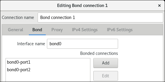
- Optional: Set other options, such as the Media Independent Interface (MII) monitoring interval.
-
Optional: Set the name of the bond interface in the
-
Configure the IP settings of the bond. Skip this step if you want to use this bond as a port of other devices.
-
In the
IPv4 Settingstab, configure the IPv4 settings. For example, set a static IPv4 address, network mask, default gateway, DNS server, and DNS search domain: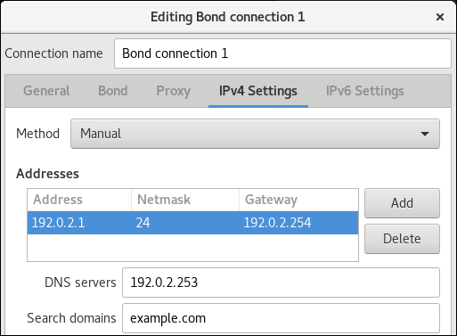
-
In the
IPv6 Settingstab, configure the IPv6 settings. For example, set a static IPv6 address, network mask, default gateway, DNS server, and DNS search domain:
-
-
Click
to save the bond connection.
-
Close
nm-connection-editor.
Verification steps
-
Temporarily remove the network cable from the host.
Note that there is no method to properly test link failure events using software utilities. Tools that deactivate connections, such as
nmcli, show only the bonding driver’s ability to handle port configuration changes and not actual link failure events. -
Display the status of the bond:
#
cat /proc/net/bonding/
bond0
Additional resources
- Configuring NetworkManager to avoid using a specific profile to provide a default gateway
- Configuring a network team using nm-connection-editor
- Configuring a network bridge using nm-connection-editor
- Configuring VLAN tagging using nm-connection-editor
9.9. Configuring a network bond using nmstatectl
To configure a network bond using the Nmstate API, use the nmstatectl utility.
For example, the procedure below creates a bond in NetworkManager with the following settings:
-
Network interfaces in the bond:
enp1s0andenp7s0 -
Mode:
active-backup -
Static IPv4 address:
192.0.2.1with a/24subnet mask -
Static IPv6 address:
2001:db8:1::1with a/64subnet mask -
IPv4 default gateway:
192.0.2.254 -
IPv6 default gateway:
2001:db8:1::fffe -
IPv4 DNS server:
192.0.2.200 -
IPv6 DNS server:
2001:db8:1::ffbb -
DNS search domain:
example.com
Prerequisites
- Two or more physical or virtual network devices are installed on the server.
- To use Ethernet devices as ports in the bond, the physical or virtual Ethernet devices must be installed on the server.
-
To use team, bridge, or VLAN devices as ports in the bond, set the interface name in the
portlist, and define the corresponding interfaces. -
The
nmstatepackage is installed.
Procedure
-
Create a YAML file, for example
~/create-bond.yml, with the following contents:--- interfaces: - name: bond0 type: bond state: up ipv4: enabled: true address: - ip: 192.0.2.1 prefix-length: 24 dhcp: false ipv6: enabled: true address: - ip: 2001:db8:1::1 prefix-length: 64 autoconf: false dhcp: false link-aggregation: mode: active-backup port: - enp1s0 - enp7s0 - name: enp1s0 type: ethernet state: up - name: enp7s0 type: ethernet state: up routes: config: - destination: 0.0.0.0/0 next-hop-address: 192.0.2.254 next-hop-interface: bond0 - destination: ::/0 next-hop-address: 2001:db8:1::fffe next-hop-interface: bond0 dns-resolver: config: search: - example.com server: - 192.0.2.200 - 2001:db8:1::ffbb -
Apply the settings to the system:
#
nmstatectl apply ~/create-bond.yml
Verification steps
-
Display the status of the devices and connections:
#
nmcli device status
DEVICE TYPE STATE CONNECTIONbond0
bondconnected
bond0
-
Display all settings of the connection profile:
#
nmcli connection show
connection.id:bond0
bond0
connection.uuid:79cbc3bd-302e-4b1f-ad89-f12533b818ee
connection.stable-id: -- connection.type: bond connection.interface-name:bond0
... -
Display the connection settings in YAML format:
#
nmstatectl show
bond0
Additional resources
-
nmstatectl(8)man page -
/usr/share/doc/nmstate/examples/directory
9.10. Configuring a network bond using RHEL System Roles
You can use the network RHEL System Roles to configure a Linux bond. For example, use it to configure a network bond in active-backup mode that uses two Ethernet devices, and sets an IPv4 and IPv6 addresses, default gateways, and DNS configuration.
Note
Set the IP configuration on the bond and not on the ports of the Linux bond.
Perform this procedure on the Ansible control node.
Prerequisites
- You have prepared the control node and the managed nodes
- You are logged in to the control node as a user who can run playbooks on the managed nodes.
-
The account you use to connect to the managed nodes has
sudopermissions on them. - The hosts or host groups on which you want to run this playbook are listed in the Ansible inventory file.
- Two or more physical or virtual network devices are installed on the server.
Procedure
-
Create a playbook file, for example
~/bond-ethernet.yml, with the following content:--- - name: Configure the network hosts:
managed-node-01.example.com
tasks: name: Configure a network bond that uses two Ethernet ports - include_role: name: rhel-system-roles.network vars: network_connections: # Define the bond profile - name: bond0 type: bond interface_name: bond0 ip: address: - "192.0.2.1/24" - "2001:db8:1::1/64" gateway4: 192.0.2.254 gateway6: 2001:db8:1::fffe dns: - 192.0.2.200 - 2001:db8:1::ffbb dns_search: - example.com bond: mode: active-backup state: up # Add an Ethernet profile to the bond - name: bond0-port1 interface_name: enp7s0 type: ethernet controller: bond0 state: up # Add a second Ethernet profile to the bond - name: bond0-port2 interface_name: enp8s0 type: ethernet controller: bond0 state: up -
Run the playbook:
#
ansible-playbook
~/bond-ethernet.yml
Additional resources
-
/usr/share/ansible/roles/rhel-system-roles.network/README.mdfile
9.11. Creating a network bond to enable switching between an Ethernet and wireless connection without interrupting the VPN
RHEL users who connect their workstation to their company’s network typically use a VPN to access remote resources. However, if the workstation switches between an Ethernet and Wi-Fi connection, for example, if you release a laptop from a docking station with an Ethernet connection, the VPN connection is interrupted. To avoid this problem, you can create a network bond that uses the Ethernet and Wi-Fi connection in active-backup mode.
Prerequisites
- The host contains an Ethernet and a Wi-Fi device.
-
An Ethernet and Wi-Fi NetworkManager connection profile has been created and both connections work independently.
This procedure uses the following connection profiles to create a network bond named
bond0:-
Docking_stationassociated with theenp11s0u1Ethernet device -
Wi-Fiassociated with thewlp1s0Wi-Fi device
-
Procedure
-
Create a bond interface in
active-backupmode:#
nmcli connection add type bond con-name bond0 ifname bond0 bond.options "mode=active-backup"
This command names both the interface and connection profile
bond0. -
Configure the IPv4 settings of the bond:
- If a DHCP server in your network assigns IPv4 addresses to hosts, no action is required.
-
If your local network requires static IPv4 addresses, set the address, network mask, default gateway, DNS server, and DNS search domain to the
bond0connection:#
nmcli connection modify bond0 ipv4.addresses '
#192.0.2.1/24
'nmcli connection modify bond0 ipv4.gateway '
#192.0.2.254
'nmcli connection modify bond0 ipv4.dns '
#192.0.2.253
'nmcli connection modify bond0 ipv4.dns-search '
#example.com
'nmcli connection modify bond0 ipv4.method manual
-
Configure the IPv6 settings of the bond:
- If your router or a DHCP server in your network assigns IPv6 addresses to hosts, no action is required.
-
If your local network requires static IPv6 addresses, set the address, network mask, default gateway, DNS server, and DNS search domain to the
bond0connection:#
nmcli connection modify bond0 ipv6.addresses '
#2001:db8:1::1/64
'nmcli connection modify bond0 ipv6.gateway '
#2001:db8:1::fffe
'nmcli connection modify bond0 ipv6.dns '
#2001:db8:1::fffd
'nmcli connection modify bond0 ipv6.dns-search '
#example.com
'nmcli connection modify bond0 ipv6.method manual
-
Display the connection profiles:
# nmcli connection show
NAME             UUID                                  TYPE      DEVICE
Docking_station  256dd073-fecc-339d-91ae-9834a00407f9  ethernet  enp11s0u1
Wi-Fi            1f1531c7-8737-4c60-91af-2d21164417e8  wifi      wlp1s0
...
You require the names of the connection profiles and the Ethernet device name in the next steps.
-
Assign the connection profile of the Ethernet connection to the bond:
#
nmcli connection modify
Docking_station
master bond0 -
Assign the connection profile of the Wi-Fi connection to the bond:
#
nmcli connection modify
Wi-Fi
master bond0 -
If your Wi-Fi network uses MAC filtering to allow only MAC addresses on a allow list to access the network, configure that NetworkManager dynamically assigns the MAC address of the active port to the bond:
#
nmcli connection modify bond0 +bond.options fail_over_mac=1
With this setting, you must set only the MAC address of the Wi-Fi device to the allow list instead of the MAC address of both the Ethernet and Wi-Fi device.
-
Set the device associated with the Ethernet connection as primary device of the bond:
#
nmcli con modify bond0 +bond.options "primary=enp11s0u1"
With this setting, the bond always uses the Ethernet connection if it is available.
-
Configure that NetworkManager automatically activates ports when the
bond0device is activated:#
nmcli connection modify bond0 connection.autoconnect-slaves 1
-
Activate the
bond0connection:#
nmcli connection up bond0
Verification steps
-
Display the currently active device, the status of the bond and its ports:
#
cat /proc/net/bonding/bond0
Ethernet Channel Bonding Driver: v3.7.1 (April 27, 2011) Bonding Mode: fault-tolerance (active-backup) (fail_over_mac active) Primary Slave: enp11s0u1 (primary_reselect always)Currently Active Slave: enp11s0u1
MII Status: up
MII Polling Interval (ms): 1 Up Delay (ms): 0 Down Delay (ms): 0 Peer Notification Delay (ms): 0 Slave Interface: enp11s0u1MII Status: up
Speed: 1000 Mbps Duplex: full Link Failure Count: 0 Permanent HW addr: 00:53:00:59:da:b7 Slave queue ID: 0 Slave Interface: wlp1s0MII Status: up
Speed: Unknown Duplex: Unknown Link Failure Count: 2 Permanent HW addr: 00:53:00:b3:22:ba Slave queue ID: 0
Additional resources
- Configuring an Ethernet connection
- Managing Wi-Fi connections
- Configuring network bonding
9.12. The different network bonding modes
The Linux bonding driver provides link aggregation. Bonding is the process of aggregating multiple network interfaces in parallel to provide a single logical bonded interface. The actions of a bonded interface depend on the bonding policy that is also known as mode. The different modes provide either load-balancing or hot standby services.
The following modes exist:
-
Balance-rr (Mode 0)
-
Balance-rruses the round-robin algorithm that sequentially transmits packets from the first available port to the last one. This mode provides load balancing and fault tolerance.This mode requires switch configuration of a port aggregation group, also called EtherChannel or similar port grouping. An EtherChannel is a port link aggregation technology to group multiple physical Ethernet links to one logical Ethernet link.
The drawback of this mode is that it is not suitable for heavy workloads and if TCP throughput or ordered packet delivery is essential.
-
Active-backup (Mode 1)
-
Active-backupuses the policy that determines that only one port is active in the bond. This mode provides fault tolerance and does not require any switch configuration.If the active port fails, an alternate port becomes active. The bond sends a gratuitous address resolution protocol (ARP) response to the network. The gratuitous ARP forces the receiver of the ARP frame to update their forwarding table. The
Active-backupmode transmits a gratuitous ARP to announce the new path to maintain connectivity for the host.The
primaryoption defines the preferred port of the bonding interface. -
Balance-xor (Mode 2)
-
Balance-xoruses the selected transmit hash policy to send the packets. This mode provides load balancing, fault tolerance, and requires switch configuration to set up an Etherchannel or similar port grouping.To alter packet transmission and balance transmit, this mode uses the
xmit_hash_policyoption. Depending on the source or destination of traffic on the interface, the interface requires an additional load-balancing configuration. See description xmit_hash_policy bonding parameter. -
Broadcast (Mode 3)
-
Broadcastuses a policy that transmits every packet on all interfaces. This mode provides fault tolerance and requires a switch configuration to set up an EtherChannel or similar port grouping.The drawback of this mode is that it is not suitable for heavy workloads and if TCP throughput or ordered packet delivery is essential.
-
802.3ad (Mode 4)
-
802.3aduses the same-named IEEE standard dynamic link aggregation policy. This mode provides fault tolerance. This mode requires switch configuration to set up a Link Aggregation Control Protocol (LACP) port grouping.This mode creates aggregation groups that share the same speed and duplex settings and utilizes all ports in the active aggregator. Depending on the source or destination of traffic on the interface, this mode requires an additional load-balancing configuration.
By default, the port selection for outgoing traffic depends on the transmit hash policy. Use the
xmit_hash_policyoption of the transmit hash policy to change the port selection and balance transmit.The difference between the
802.3adand theBalance-xoris compliance. The802.3adpolicy negotiates LACP between the port aggregation groups. See description xmit_hash_policy bonding parameter -
Balance-tlb (Mode 5)
-
Balance-tlbuses the transmit load balancing policy. This mode provides fault tolerance, load balancing, and establishes channel bonding that does not require any switch support.The active port receives the incoming traffic. In case of failure of the active port, another one takes over the MAC address of the failed port. To decide which interface processes the outgoing traffic, use one of the following modes:
-
Value
0: Uses the hash distribution policy to distribute traffic without load balancing -
Value
1: Distributes traffic to each port by using load balancingWith the bonding option
tlb_dynamic_lb=0, this bonding mode uses thexmit_hash_policybonding option to balance transmit. Theprimaryoption defines the preferred port of the bonding interface.
See description xmit_hash_policy bonding parameter.
-
Value
-
Balance-alb (Mode 6)
-
Balance-albuses an adaptive load balancing policy. This mode provides fault tolerance, load balancing, and does not require any special switch support.This mode Includes balance-transmit load balancing (
balance-tlb) and receive-load balancing for IPv4 and IPv6 traffic. The bonding intercepts ARP replies sent by the local system and overwrites the source hardware address of one of the ports in the bond. ARP negotiation manages the receive-load balancing. Therefore, different ports use different hardware addresses for the server.The
primaryoption defines the preferred port of the bonding interface. With the bonding optiontlb_dynamic_lb=0, this bonding mode uses thexmit_hash_policybonding option to balance transmit. See description xmit_hash_policy bonding parameter.
Additional resources
-
/usr/share/doc/kernel-doc-<provided by theversion
>/Documentation/networking/bonding.rst
kernel-docpackage -
/usr/share/doc/kernel-doc-<provided by theversion
>/Documentation/networking/bonding.txt
kernel-docpackage - Which bonding modes work when used with a bridge that virtual machine guests or containers connect to?
- How are the values for different policies in “xmit_hash_policy” bonding parameter calculated?
9.13. The xmit_hash_policy bonding parameter
The xmit_hash_policy load balancing parameter selects the transmit hash policy for a node selection in the balance-xor, 802.3ad, balance-alb, and balance-tlb modes. It is only applicable to mode 5 and 6 if the tlb_dynamic_lb parameter is 0. The possible values of this parameter are layer2, layer2+3, layer3+4, encap2+3, encap3+4, and vlan+srcmac.
Refer the table for details:
Policy or Network layers
Layer2
Layer2+3
Layer3+4
encap2+3
encap3+4
VLAN+srcmac
Uses
XOR of source and destination MAC addresses and Ethernet protocol type
XOR of source and destination MAC addresses and IP addresses
XOR of source and destination ports and IP addresses
XOR of source and destination MAC addresses and IP addresses inside a supported tunnel, for example, Virtual Extensible LAN (VXLAN). This mode relies on skb_flow_dissect() function to obtain the header fields
XOR of source and destination ports and IP addresses inside a supported tunnel, for example, VXLAN. This mode relies on skb_flow_dissect() function to obtain the header fields
XOR of VLAN ID and source MAC vendor and source MAC device
Placement of traffic
All traffic to a particular network peer on the same underlying network interface
All traffic to a particular IP address on the same underlying network interface
All traffic to a particular IP address and port on the same underlying network interface
Primary choice
If network traffic is between this system and multiple other systems in the same broadcast doma0in
If network traffic between this system and multiple other systems goes through a default gateway
If network traffic between this system and another system uses the same IP addresses but goes through multiple ports
The encapsulated traffic is between the source system and multiple other systems using multiple IP addresses
The encapsulated traffic is between the source system and other systems using multiple port numbers
If the bond carries network traffic, from multiple containers or virtual machines (VM), that expose their MAC address directly to the external network such as the bridge network, and you can not configure a switch for Mode 2 or Mode 4
Secondary choice
If network traffic is mostly between this system and multiple other systems behind a default gateway
If network traffic is mostly between this system and another system
Compliant
802.3ad
802.3ad
Not 802.3ad
Default policy
This is the default policy if no configuration is provided
For non-IP traffic, the formula is the same as for the layer2 transmit policy
For non-IP traffic, the formula is the same as for the layer2 transmit policy
Chapter 10. Configuring a VPN connection
A virtual private network (VPN) is a way of connecting to a local network over the Internet. IPsec provided by Libreswan is the preferred method for creating a VPN. Libreswan is a user-space IPsec implementation for VPN. A VPN enables the communication between your LAN, and another, remote LAN by setting up a tunnel across an intermediate network such as the Internet. For security reasons, a VPN tunnel always uses authentication and encryption. For cryptographic operations, Libreswan uses the NSS library.
10.1. Configuring a VPN connection with control-center
If you use Red Hat Enterprise Linux with a graphical interface, you can configure a VPN connection in the GNOME control-center.
Prerequisites
-
The
NetworkManager-libreswan-gnomepackage is installed.
Procedure
-
Press the
Super
key, type
Settings, and pressEnter
to open the
control-centerapplication. -
Select the
Networkentry on the left. -
Click the
+
icon.
-
Select
VPN. -
Select the
Identitymenu entry to see the basic configuration options:General
Gateway— The name orIPaddress of the remote VPN gateway.Authentication
Type-
IKEv2 (Certificate)– client is authenticated by certificate. It is more secure (default). -
IKEv1 (XAUTH)– client is authenticated by user name and password, or a pre-shared key (PSK).The following configuration settings are available under the
Advancedsection:Figure 10.1. Advanced options of a VPN connection
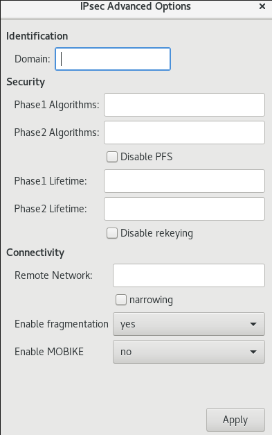
Warning
When configuring an IPsec-based VPN connection using the
gnome-control-centerapplication, theAdvanceddialog displays the configuration, but it does not allow any changes. As a consequence, users cannot change any advanced IPsec options. Use thenm-connection-editorornmclitools instead to perform configuration of the advanced properties.Identification
-
Domain— If required, enter the Domain Name.Security
-
Phase1 Algorithms— corresponds to theikeLibreswan parameter — enter the algorithms to be used to authenticate and set up an encrypted channel. -
Phase2 Algorithms— corresponds to theespLibreswan parameter — enter the algorithms to be used for theIPsecnegotiations.Check the
Disable PFSfield to turn off Perfect Forward Secrecy (PFS) to ensure compatibility with old servers that do not support PFS. -
Phase1 Lifetime— corresponds to theikelifetimeLibreswan parameter — how long the key used to encrypt the traffic will be valid. -
Phase2 Lifetime— corresponds to thesalifetimeLibreswan parameter — how long a particular instance of a connection should last before expiring.Note that the encryption key should be changed from time to time for security reasons.
-
Remote network— corresponds to therightsubnetLibreswan parameter — the destination private remote network that should be reached through the VPN.Check the
narrowingfield to enable narrowing. Note that it is only effective in IKEv2 negotiation. -
Enable fragmentation— corresponds to thefragmentationLibreswan parameter — whether or not to allow IKE fragmentation. Valid values areyes(default) orno. -
Enable Mobike— corresponds to themobikeLibreswan parameter — whether to allow Mobility and Multihoming Protocol (MOBIKE, RFC 4555) to enable a connection to migrate its endpoint without needing to restart the connection from scratch. This is used on mobile devices that switch between wired, wireless, or mobile data connections. The values areno(default) oryes.
-
-
Select the IPv4 menu entry:
IPv4 Method
-
Automatic (DHCP)— Choose this option if the network you are connecting to uses aDHCPserver to assign dynamicIPaddresses. -
Link-Local Only— Choose this option if the network you are connecting to does not have aDHCPserver and you do not want to assignIPaddresses manually. Random addresses will be assigned as per RFC 3927169.254/16. -
Manual— Choose this option if you want to assignIPaddresses manually. -
Disable—IPv4is disabled for this connection.DNS
In the
DNSsection, whenAutomaticisON, switch it toOFFto enter the IP address of a DNS server you want to use separating the IPs by comma.Routes
Note that in the
Routessection, whenAutomaticisON, routes from DHCP are used, but you can also add additional static routes. WhenOFF, only static routes are used. -
Address— Enter theIPaddress of a remote network or host. -
Netmask— The netmask or prefix length of theIPaddress entered above. -
Gateway— TheIPaddress of the gateway leading to the remote network or host entered above. -
Metric— A network cost, a preference value to give to this route. Lower values will be preferred over higher values.Use this connection only for resources on its network
Select this check box to prevent the connection from becoming the default route. Selecting this option means that only traffic specifically destined for routes learned automatically over the connection or entered here manually is routed over the connection.
-
-
To configure
IPv6settings in aVPNconnection, select the IPv6 menu entry:IPv6 Method
-
Automatic— Choose this option to useIPv6Stateless Address AutoConfiguration (SLAAC) to create an automatic, stateless configuration based on the hardware address and Router Advertisements (RA). -
Automatic, DHCP only— Choose this option to not use RA, but request information fromDHCPv6directly to create a stateful configuration. -
Link-Local Only— Choose this option if the network you are connecting to does not have aDHCPserver and you do not want to assignIPaddresses manually. Random addresses will be assigned as per RFC 4862FE80::0. -
Manual— Choose this option if you want to assignIPaddresses manually. -
Disable—IPv6is disabled for this connection.Note that
DNS,Routes,Use this connection only for resources on its networkare common toIPv4settings.
-
-
Once you have finished editing the
VPNconnection, click thebutton to customize the configuration or the
button to save it for the existing one.
-
Switch the profile to
ONto active theVPNconnection.
Additional resources
-
nm-settings-libreswan(5)
10.2. Configuring a VPN connection using nm-connection-editor
If you use Red Hat Enterprise Linux with a graphical interface, you can configure a VPN connection in the nm-connection-editor application.
Prerequisites
-
The
NetworkManager-libreswan-gnomepackage is installed. -
If you configure an Internet Key Exchange version 2 (IKEv2) connection:
- The certificate is imported into the IPsec network security services (NSS) database.
- The nickname of the certificate in the NSS database is known.
Procedure
-
Open a terminal, and enter:
$
nm-connection-editor
-
Click the
button to add a new connection.
-
Select the
IPsec based VPNconnection type, and click.
-
On the
VPNtab:-
Enter the host name or IP address of the VPN gateway into the
Gatewayfield, and select an authentication type. Based on the authentication type, you must enter different additional information:-
IKEv2 (Certifiate)authenticates the client by using a certificate, which is more secure. This setting requires the nickname of the certificate in the IPsec NSS database -
IKEv1 (XAUTH)authenticates the user by using a user name and password (pre-shared key). This setting requires that you enter the following values:- User name
- Password
- Group name
- Secret
-
-
If the remote server specifies a local identifier for the IKE exchange, enter the exact string in the
Remote IDfield. In the remote server runs Libreswan, this value is set in the server’sleftidparameter.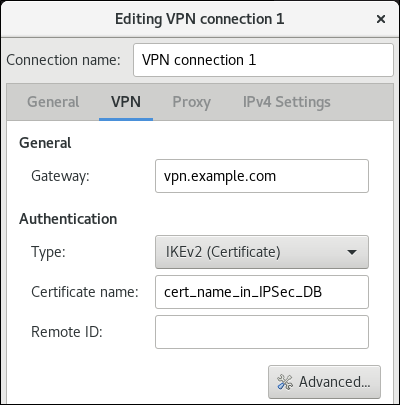
-
Optionally, configure additional settings by clicking the Advanced button. You can configure the following settings:
-
Identification
-
Domain— If required, enter the domain name.
-
-
Security
-
Phase1 Algorithmscorresponds to theikeLibreswan parameter. Enter the algorithms to be used to authenticate and set up an encrypted channel. -
Phase2 Algorithmscorresponds to theespLibreswan parameter. Enter the algorithms to be used for theIPsecnegotiations.Check the
Disable PFSfield to turn off Perfect Forward Secrecy (PFS) to ensure compatibility with old servers that do not support PFS. -
Phase1 Lifetimecorresponds to theikelifetimeLibreswan parameter. This parameter defines how long the key used to encrypt the traffic is valid. -
Phase2 Lifetimecorresponds to thesalifetimeLibreswan parameter. This parameter defines how long a security association is valid.
-
-
Connectivity
-
Remote networkcorresponds to therightsubnetLibreswan parameter and defines the destination private remote network that should be reached through the VPN.Check the
narrowingfield to enable narrowing. Note that it is only effective in the IKEv2 negotiation. -
Enable fragmentationcorresponds to thefragmentationLibreswan parameter and defines whether or not to allow IKE fragmentation. Valid values areyes(default) orno. -
Enable Mobikecorresponds to themobikeLibreswan parameter. The parameter defines whether to allow Mobility and Multihoming Protocol (MOBIKE) (RFC 4555) to enable a connection to migrate its endpoint without needing to restart the connection from scratch. This is used on mobile devices that switch between wired, wireless or mobile data connections. The values areno(default) oryes.
-
-
-
-
On the
IPv4 Settingstab, select the IP assignment method and, optionally, set additional static addresses, DNS servers, search domains, and routes.
- Save the connection.
-
Close
nm-connection-editor.
Note
When you add a new connection by clicking the + button, NetworkManager creates a new configuration file for that connection and then opens the same dialog that is used for editing an existing connection. The difference between these dialogs is that an existing connection profile has a Details menu entry.
Additional resources
-
nm-settings-libreswan(5)man page
10.3. Configuring automatic detection and usage of ESP hardware offload to accelerate an IPsec connection
Offloading Encapsulating Security Payload (ESP) to the hardware accelerates IPsec connections over Ethernet. By default, Libreswan detects if hardware supports this feature and, as a result, enables ESP hardware offload. In case that the feature was disabled or explicitly enabled, you can switch back to automatic detection.
Prerequisites
- The network card supports ESP hardware offload.
- The network driver supports ESP hardware offload.
- The IPsec connection is configured and works.
Procedure
-
Edit the Libreswan configuration file in the
/etc/ipsec.d/directory of the connection that should use automatic detection of ESP hardware offload support. -
Ensure the
nic-offloadparameter is not set in the connection’s settings. -
If you removed
nic-offload, restart theipsecservice:#
systemctl restart ipsec
Verification
If the network card supports ESP hardware offload support, following these steps to verify the result:
-
Display the
tx_ipsecandrx_ipseccounters of the Ethernet device the IPsec connection uses:#
ethtool -Stx_ipsec: 10 rx_ipsec: 10enp1s0
| egrep "_ipsec" -
Send traffic through the IPsec tunnel. For example, ping a remote IP address:
#
ping -c 5remote_ip_address
-
Display the
tx_ipsecandrx_ipseccounters of the Ethernet device again:#
ethtool -Stx_ipsec: 15 rx_ipsec: 15enp1s0
| egrep "_ipsec"If the counter values have increased, ESP hardware offload works.
Additional resources
- Configuring a VPN with IPsec
10.4. Configuring ESP hardware offload on a bond to accelerate an IPsec connection
Offloading Encapsulating Security Payload (ESP) to the hardware accelerates IPsec connections. If you use a network bond for fail-over reasons, the requirements and the procedure to configure ESP hardware offload are different from those using a regular Ethernet device. For example, in this scenario, you enable the offload support on the bond, and the kernel applies the settings to the ports of the bond.
Prerequisites
- All network cards in the bond support ESP hardware offload.
-
The network driver supports ESP hardware offload on a bond device. In RHEL, only the
ixgbedriver supports this feature. - The bond is configured and works.
-
The bond uses the
active-backupmode. The bonding driver does not support any other modes for this feature. - The IPsec connection is configured and works.
Procedure
-
Enable ESP hardware offload support on the network bond:
#
nmcli connection modify
bond0
ethtool.feature-esp-hw-offload onThis command enables ESP hardware offload support on the
bond0connection. -
Reactivate the
bond0connection:#
nmcli connection up
bond0
-
Edit the Libreswan configuration file in the
/etc/ipsec.d/directory of the connection that should use ESP hardware offload, and append thenic-offload=yesstatement to the connection entry:conn
example
...nic-offload=yes
-
Restart the
ipsecservice:#
systemctl restart ipsec
Verification
-
Display the active port of the bond:
#
grep "Currently Active Slave" /proc/net/bonding/
Currently Active Slave:bond0
enp1s0
-
Display the
tx_ipsecandrx_ipseccounters of the active port:#
ethtool -S
tx_ipsec: 10 rx_ipsec: 10enp1s0
| egrep "_ipsec" -
Send traffic through the IPsec tunnel. For example, ping a remote IP address:
#
ping -c 5
remote_ip_address
-
Display the
tx_ipsecandrx_ipseccounters of the active port again:#
ethtool -S enp1s0 | egrep "_ipsec"
tx_ipsec: 15 rx_ipsec: 15If the counter values have increased, ESP hardware offload works.
Additional resources
- Configuring network bonding
- Configuring a VPN with IPsec section in the Securing networks document
Chapter 11. Configuring IP tunnels
Similar to a VPN, an IP tunnel directly connects two networks over a third network, such as the Internet. However, not all tunnel protocols support encryption.
The routers in both networks that establish the tunnel requires at least two interfaces:
- One interface that is connected to the local network
- One interface that is connected to the network through which the tunnel is established.
To establish the tunnel, you create a virtual interface on both routers with an IP address from the remote subnet.
NetworkManager supports the following IP tunnels:
- Generic Routing Encapsulation (GRE)
- Generic Routing Encapsulation over IPv6 (IP6GRE)
- Generic Routing Encapsulation Terminal Access Point (GRETAP)
- Generic Routing Encapsulation Terminal Access Point over IPv6 (IP6GRETAP)
- IPv4 over IPv4 (IPIP)
- IPv4 over IPv6 (IPIP6)
- IPv6 over IPv6 (IP6IP6)
- Simple Internet Transition (SIT)
Depending on the type, these tunnels act either on layer 2 or 3 of the Open Systems Interconnection (OSI) model.
11.1. Configuring an IPIP tunnel using nmcli to encapsulate IPv4 traffic in IPv4 packets
An IP over IP (IPIP) tunnel operates on OSI layer 3 and encapsulates IPv4 traffic in IPv4 packets as described in RFC 2003.
Important
Data sent through an IPIP tunnel is not encrypted. For security reasons, use the tunnel only for data that is already encrypted, for example, by other protocols, such as HTTPS.
Note that IPIP tunnels support only unicast packets. If you require an IPv4 tunnel that supports multicast, see Configuring a GRE tunnel using nmcli to encapsulate layer-3 traffic in IPv4 packets.
For example, you can create an IPIP tunnel between two RHEL routers to connect two internal subnets over the Internet as shown in the following diagram:

Prerequisites
- Each RHEL router has a network interface that is connected to its local subnet.
- Each RHEL router has a network interface that is connected to the Internet.
- The traffic you want to send through the tunnel is IPv4 unicast.
Procedure
-
On the RHEL router in network A:
-
Create an IPIP tunnel interface named
tun0:#
nmcli connection add type ip-tunnel ip-tunnel.mode ipip con-name tun0 ifname tun0 remote 198.51.100.5 local 203.0.113.10
The
remoteandlocalparameters set the public IP addresses of the remote and the local routers. -
Set the IPv4 address to the
tun0device:#
nmcli connection modify tun0 ipv4.addresses '10.0.1.1/30'
Note that a
/30subnet with two usable IP addresses is sufficient for the tunnel. -
Configure the
tun0connection to use a manual IPv4 configuration:#
nmcli connection modify tun0 ipv4.method manual
-
Add a static route that routes traffic to the
172.16.0.0/24network to the tunnel IP on router B:#
nmcli connection modify tun0 +ipv4.routes "172.16.0.0/24 10.0.1.2"
-
Enable the
tun0connection.#
nmcli connection up tun0
-
Enable packet forwarding:
#
echo "net.ipv4.ip_forward=1" > /etc/sysctl.d/95-IPv4-forwarding.conf
#sysctl -p /etc/sysctl.d/95-IPv4-forwarding.conf
-
-
On the RHEL router in network B:
-
Create an IPIP tunnel interface named
tun0:#
nmcli connection add type ip-tunnel ip-tunnel.mode ipip con-name tun0 ifname tun0 remote 203.0.113.10 local 198.51.100.5
The
remoteandlocalparameters set the public IP addresses of the remote and local routers. -
Set the IPv4 address to the
tun0device:#
nmcli connection modify tun0 ipv4.addresses '10.0.1.2/30'
-
Configure the
tun0connection to use a manual IPv4 configuration:#
nmcli connection modify tun0 ipv4.method manual
-
Add a static route that routes traffic to the
192.0.2.0/24network to the tunnel IP on router A:#
nmcli connection modify tun0 +ipv4.routes "192.0.2.0/24 10.0.1.1"
-
Enable the
tun0connection.#
nmcli connection up tun0
-
Enable packet forwarding:
#
echo "net.ipv4.ip_forward=1" > /etc/sysctl.d/95-IPv4-forwarding.conf
#sysctl -p /etc/sysctl.d/95-IPv4-forwarding.conf
-
Verification steps
-
From each RHEL router, ping the IP address of the internal interface of the other router:
-
On Router A, ping
172.16.0.1:#
ping 172.16.0.1
-
On Router B, ping
192.0.2.1:#
ping 192.0.2.1
-
Additional resources
-
nmcli(1)man page -
nm-settings(5)man page
11.2. Configuring a GRE tunnel using nmcli to encapsulate layer-3 traffic in IPv4 packets
A Generic Routing Encapsulation (GRE) tunnel encapsulates layer-3 traffic in IPv4 packets as described in RFC 2784. A GRE tunnel can encapsulate any layer 3 protocol with a valid Ethernet type.
Important
Data sent through a GRE tunnel is not encrypted. For security reasons, use the tunnel only for data that is already encrypted, for example, by other protocols, such as HTTPS.
For example, you can create a GRE tunnel between two RHEL routers to connect two internal subnets over the Internet as shown in the following diagram:
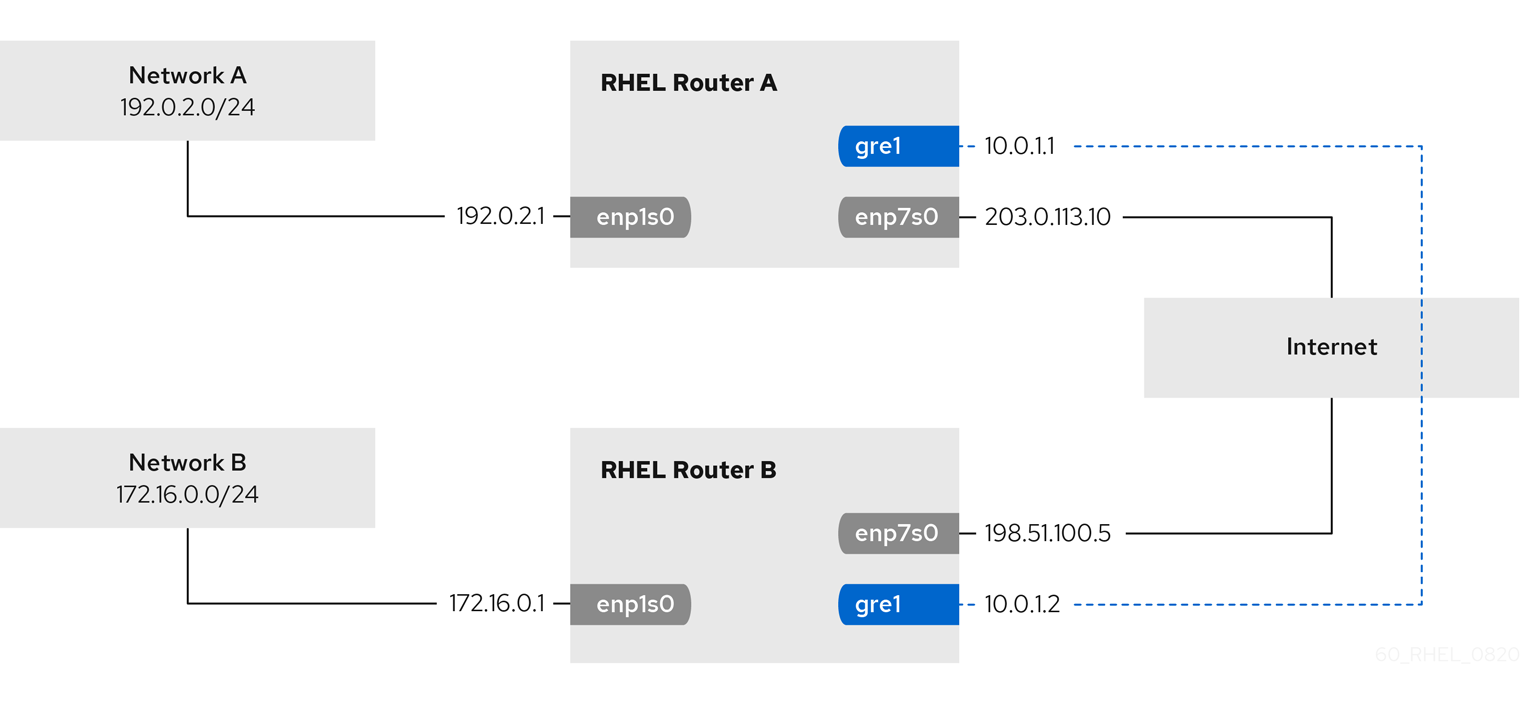
Note
The gre0 device name is reserved. Use gre1 or a different name for the device.
Prerequisites
- Each RHEL router has a network interface that is connected to its local subnet.
- Each RHEL router has a network interface that is connected to the Internet.
Procedure
-
On the RHEL router in network A:
-
Create a GRE tunnel interface named
gre1:#
nmcli connection add type ip-tunnel ip-tunnel.mode gre con-name gre1 ifname gre1 remote 198.51.100.5 local 203.0.113.10
The
remoteandlocalparameters set the public IP addresses of the remote and the local routers. -
Set the IPv4 address to the
gre1device:#
nmcli connection modify gre1 ipv4.addresses '10.0.1.1/30'
Note that a
/30subnet with two usable IP addresses is sufficient for the tunnel. -
Configure the
gre1connection to use a manual IPv4 configuration:#
nmcli connection modify gre1 ipv4.method manual
-
Add a static route that routes traffic to the
172.16.0.0/24network to the tunnel IP on router B:#
nmcli connection modify gre1 +ipv4.routes "172.16.0.0/24 10.0.1.2"
-
Enable the
gre1connection.#
nmcli connection up gre1
-
Enable packet forwarding:
#
echo "net.ipv4.ip_forward=1" > /etc/sysctl.d/95-IPv4-forwarding.conf
#sysctl -p /etc/sysctl.d/95-IPv4-forwarding.conf
-
-
On the RHEL router in network B:
-
Create a GRE tunnel interface named
gre1:#
nmcli connection add type ip-tunnel ip-tunnel.mode gre con-name gre1 ifname gre1 remote 203.0.113.10 local 198.51.100.5
The
remoteandlocalparameters set the public IP addresses of the remote and the local routers. -
Set the IPv4 address to the
gre1device:#
nmcli connection modify gre1 ipv4.addresses '10.0.1.2/30'
-
Configure the
gre1connection to use a manual IPv4 configuration:#
nmcli connection modify gre1 ipv4.method manual
-
Add a static route that routes traffic to the
192.0.2.0/24network to the tunnel IP on router A:#
nmcli connection modify gre1 +ipv4.routes "192.0.2.0/24 10.0.1.1"
-
Enable the
gre1connection.#
nmcli connection up gre1
-
Enable packet forwarding:
#
echo "net.ipv4.ip_forward=1" > /etc/sysctl.d/95-IPv4-forwarding.conf
#sysctl -p /etc/sysctl.d/95-IPv4-forwarding.conf
-
Verification steps
-
From each RHEL router, ping the IP address of the internal interface of the other router:
-
On Router A, ping
172.16.0.1:#
ping 172.16.0.1
-
On Router B, ping
192.0.2.1:#
ping 192.0.2.1
-
Additional resources
-
nmcli(1)man page -
nm-settings(5)man page
11.3. Configuring a GRETAP tunnel to transfer Ethernet frames over IPv4
A Generic Routing Encapsulation Terminal Access Point (GRETAP) tunnel operates on OSI level 2 and encapsulates Ethernet traffic in IPv4 packets as described in RFC 2784.
Important
Data sent through a GRETAP tunnel is not encrypted. For security reasons, establish the tunnel over a VPN or a different encrypted connection.
For example, you can create a GRETAP tunnel between two RHEL routers to connect two networks using a bridge as shown in the following diagram:
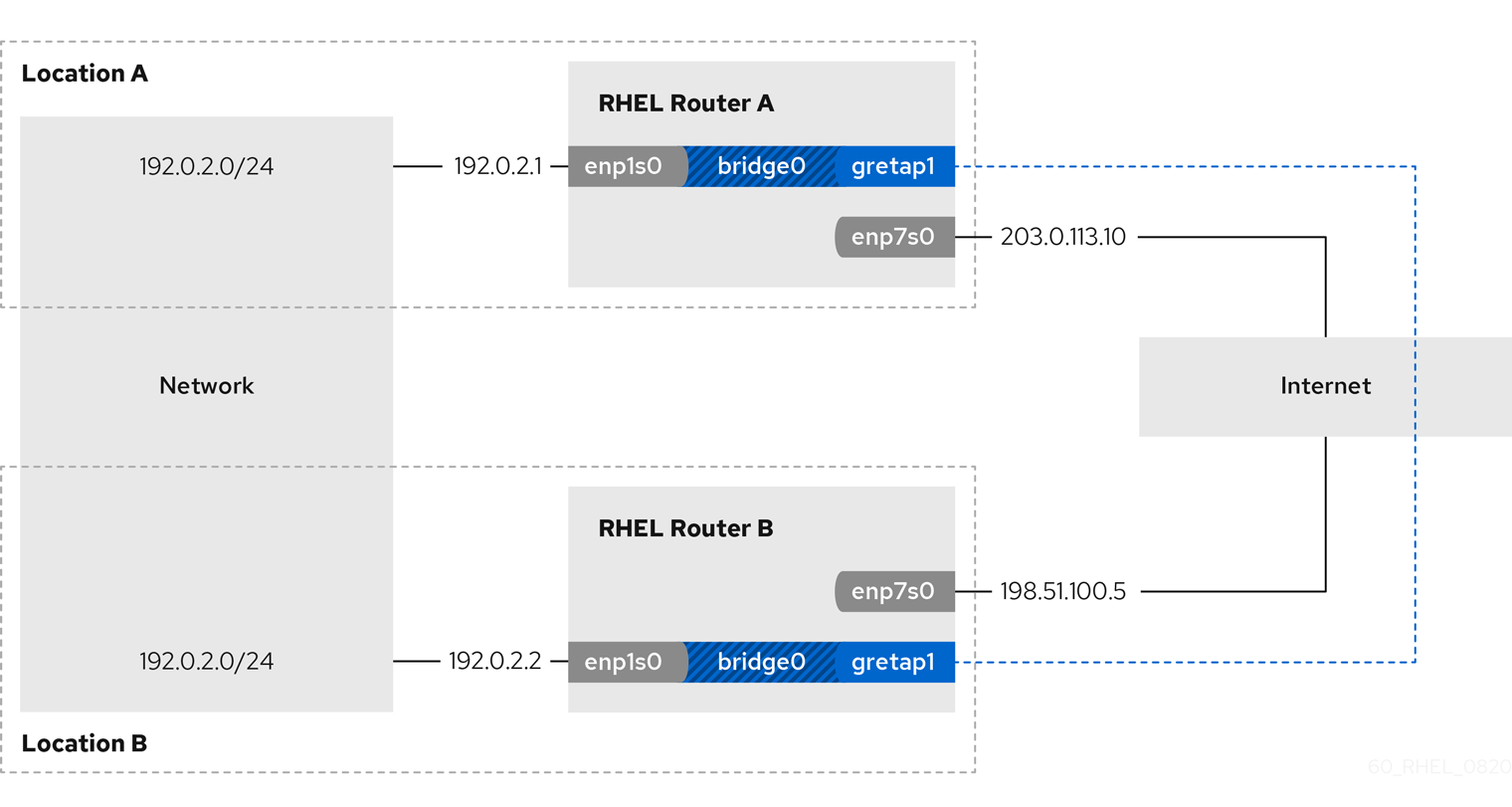
Note
The gretap0 device name is reserved. Use gretap1 or a different name for the device.
Prerequisites
- Each RHEL router has a network interface that is connected to its local network, and the interface has no IP configuration assigned.
- Each RHEL router has a network interface that is connected to the Internet.
Procedure
-
On the RHEL router in network A:
-
Create a bridge interface named
bridge0:#
nmcli connection add type bridge con-name bridge0 ifname bridge0
-
Configure the IP settings of the bridge:
#
nmcli connection modify bridge0 ipv4.addresses '192.0.2.1/24'
#nmcli connection modify bridge0 ipv4.method manual
-
Add a new connection profile for the interface that is connected to local network to the bridge:
#
nmcli connection add type ethernet slave-type bridge con-name bridge0-port1 ifname enp1s0 master bridge0
-
Add a new connection profile for the GRETAP tunnel interface to the bridge:
#
nmcli connection add type ip-tunnel ip-tunnel.mode gretap slave-type bridge con-name bridge0-port2 ifname gretap1 remote 198.51.100.5 local 203.0.113.10 master bridge0
The
remoteandlocalparameters set the public IP addresses of the remote and the local routers. -
Optional: Disable the Spanning Tree Protocol (STP) if you do not need it:
#
nmcli connection modify bridge0 bridge.stp no
By default, STP is enabled and causes a delay before you can use the connection.
-
Configure that activating the
bridge0connection automatically activates the ports of the bridge:#
nmcli connection modify bridge0 connection.autoconnect-slaves 1
-
Active the
bridge0connection:#
nmcli connection up bridge0
-
-
On the RHEL router in network B:
-
Create a bridge interface named
bridge0:#
nmcli connection add type bridge con-name bridge0 ifname bridge0
-
Configure the IP settings of the bridge:
#
nmcli connection modify bridge0 ipv4.addresses '192.0.2.2/24'
#nmcli connection modify bridge0 ipv4.method manual
-
Add a new connection profile for the interface that is connected to local network to the bridge:
#
nmcli connection add type ethernet slave-type bridge con-name bridge0-port1 ifname enp1s0 master bridge0
-
Add a new connection profile for the GRETAP tunnel interface to the bridge:
#
nmcli connection add type ip-tunnel ip-tunnel.mode gretap slave-type bridge con-name bridge0-port2 ifname gretap1 remote 203.0.113.10 local 198.51.100.5 master bridge0
The
remoteandlocalparameters set the public IP addresses of the remote and the local routers. -
Optional: Disable the Spanning Tree Protocol (STP) if you do not need it:
#
nmcli connection modify bridge0 bridge.stp no
-
Configure that activating the
bridge0connection automatically activates the ports of the bridge:#
nmcli connection modify bridge0 connection.autoconnect-slaves 1
-
Active the
bridge0connection:#
nmcli connection up bridge0
-
Verification steps
-
On both routers, verify that the
enp1s0andgretap1connections are connected and that theCONNECTIONcolumn displays the connection name of the port:#
nmcli device
nmcli device DEVICE TYPE STATE CONNECTION ... bridge0 bridge connected bridge0 enp1s0 ethernet connected bridge0-port1 gretap1 iptunnel connected bridge0-port2 -
From each RHEL router, ping the IP address of the internal interface of the other router:
-
On Router A, ping
192.0.2.2:#
ping 192.0.2.2
-
On Router B, ping
192.0.2.1:#
ping 192.0.2.1
-
Additional resources
-
nmcli(1)man page -
nm-settings(5)man page
11.4. Additional resources
-
ip-link(8)man page
Chapter 12. Changing a hostname
The hostname of a system is the name on the system itself. You can set the name when you install RHEL, and you can change it afterwards.
12.1. Changing a hostname using nmcli
You can use the nmcli utility to update the system hostname. Note that other utilities, might use a different term, such as static or persistent hostname.
Procedure
-
Optional: Display the current hostname setting:
#
nmcli general hostname
old-hostname.example.com
-
Set the new hostname:
#
nmcli general hostname
new-hostname.example.com
-
NetworkManager automatically restarts the
systemd-hostnamedto activate the new name. However, the following manual actions can be required if you do not want to reboot the host:-
Restart all services that only read the hostname when the service starts:
#
systemctl restart
service_name
- Active shell users must re-login for the changes to take effect.
-
Verification
-
Display the hostname:
#
nmcli general hostname
new-hostname.example.com
12.2. Changing a hostname using hostnamectl
You can use the hostnamectl utility to update the hostname. By default, this utility sets the following hostname types:
-
Static hostname: Stored in the
/etc/hostnamefile. Typically, services use this name as the hostname. -
Pretty hostname: A descriptive name, such as
Proxy server in data center A. - Transient hostname: A fall-back value that is typically received from the network configuration.
Procedure
-
Optional: Display the current hostname setting:
#
hostnamectl status --static
old-hostname.example.com
-
Set the new hostname:
#
hostnamectl set-hostname
new-hostname.example.com
This command sets the static, pretty, and transient hostname to the new value. To set only a specific type, pass the
--static,--pretty, or--transientoption to the command. -
The
hostnamectlutility automatically restarts thesystemd-hostnamedto activate the new name. However, the following manual actions can be required if you do not want to reboot the host:-
Restart all services that only read the hostname when the service starts:
#
systemctl restart
service_name
- Active shell users must re-login for the changes to take effect.
-
Verification
-
Display the hostname:
#
hostnamectl status --static
new-hostname.example.com
Additional resources
-
hostnamectl(1) -
systemd-hostnamed.service(8)
Chapter 13. Legacy network scripts support in RHEL
By default, RHEL uses NetworkManager to configure and manage network connections, and the /usr/sbin/ifup and /usr/sbin/ifdown scripts use NetworkManager to process ifcfg files in the /etc/sysconfig/network-scripts/ directory.
Important
The legacy scripts are deprecated in RHEL 8 and will be removed in a future major version of RHEL. If you still use the legacy network scripts, for example, because you upgraded from an earlier version to RHEL 8, Red Hat recommends that you migrate your configuration to NetworkManager.
13.1. Installing the legacy network scripts
If you require the deprecated network scripts that processes the network configuration without using NetworkManager, you can install them. In this case, the /usr/sbin/ifup and /usr/sbin/ifdown scripts link to the deprecated shell scripts that manage the network configuration.
Procedure
-
Install the
network-scriptspackage:#
yum install network-scripts
Chapter 14. Port mirroring
Network administrators can use port mirroring to replicate inbound and outbound network traffic being communicated from one network device to another. Administrators use port mirroring to monitor network traffic and collect network data to:
- Debug networking issues and tune the network flow
- Inspect and analyze the network traffic to troubleshoot networking problems
- Detect an intrusion
14.1. Mirroring a network interface using nmcli
You can configure port mirroring using NetworkManager. The following procedure mirrors the network traffic from enp1s0 to enp7s0 by adding Traffic Control (tc) rules and filters to the enp1s0 network interface.
Prerequisites
- A network interface to mirror the network traffic to.
Procedure
-
Add a network connection profile that you want to mirror the network traffic from:
#
nmcli connection add type ethernet ifname
enp1s0
con-nameenp1s0
autoconnectno
-
Attach a
prioqdisctoenp1s0for the egress (outgoing) traffic with the10:handle:#
nmcli connection modify
enp1s0
+tc.qdisc "root prio handle 10:"The
prioqdiscattached without children allows attaching filters. -
Add a
qdiscfor the ingress traffic, with theffff:handle:#
nmcli connection modify
enp1s0
+tc.qdisc "ingress handle ffff:" -
Add the following filters to match packets on the ingress and egress
qdiscs, and to mirror them toenp7s0:#
nmcli connection modify
#enp1s0
+tc.tfilter "parent ffff: matchall action mirred egress mirror devenp7s0
"nmcli connection modify
enp1s0
+tc.tfilter "parent 10: matchall action mirred egress mirror devenp7s0
"The
matchallfilter matches all packets, and themirredaction redirects packets to destination. -
Activate the connection:
#
nmcli connection up
enp1s0
Verification steps
-
Install the
tcpdumputility:#
yum install tcpdump
-
Display the traffic mirrored on the target device (
enp7s0):#
tcpdump -i
enp7s0
Additional resources
-
How to capture network packets using
tcpdump
Chapter 15. Configuring NetworkManager to ignore certain devices
By default, NetworkManager manages all devices except the lo (loopback) device. However, you can set certain devices as unmanaged to configure that NetworkManager ignores these devices. With this setting, you can manually manage these devices, for example, using a script.
15.1. Permanently configuring a device as unmanaged in NetworkManager
You can permanently configure devices as unmanaged based on several criteria, such as the interface name, MAC address, or device type.
To temporarily configure network devices as unmanaged, see Temporarily configuring a device as unmanaged in NetworkManager.
Procedure
-
Optional: Display the list of devices to identify the device or MAC address you want to set as
unmanaged:#
ip link show
... 2:enp1s0: <BROADCAST,MULTICAST,UP,LOWER_UP> mtu 1500 qdisc fq_codel state UP mode DEFAULT group default qlen 1000
link/ether 52:54:00:74:79:56 brd ff:ff:ff:ff:ff:ff
... -
Create the
/etc/NetworkManager/conf.d/99-unmanaged-devices.conffile with the following content:-
To configure a specific interface as unmanaged, add:
[keyfile]
unmanaged-devices=interface-name:
enp1s0
-
To configure a device with a specific MAC address as unmanaged, add:
[keyfile]
unmanaged-devices=mac:
52:54:00:74:79:56
-
To configure all devices of a specific type as unmanaged, add:
[keyfile]
unmanaged-devices=type:ethernet
To set multiple devices as unmanaged, separate the entries in the
unmanaged-devicesparameter with semicolon: -
-
Reload the
NetworkManagerservice:#
systemctl reload NetworkManager
Verification steps
-
Display the list of devices:
#
nmcli device status
DEVICE TYPE STATE CONNECTIONenp1s0
ethernetunmanaged
-- ...The
unmanagedstate next to theenp1s0device indicates that NetworkManager does not manage this device.
Additional resources
-
NetworkManager.conf(5)man page
15.2. Temporarily configuring a device as unmanaged in NetworkManager
You can temporarily configure devices as unmanaged.
Use this method, for example, for testing purposes. To permanently configure network devices as unmanaged, see Permanently configuring a device as unmanaged in NetworkManager.
Procedure
-
Optional: Display the list of devices to identify the device you want to set as
unmanaged:#
nmcli device status
DEVICE TYPE STATE CONNECTIONenp1s0
ethernet disconnected -- ... -
Set the
enp1s0device to theunmanagedstate:#
nmcli device set
enp1s0
managed no
Verification steps
-
Display the list of devices:
#
nmcli device status
DEVICE TYPE STATE CONNECTIONenp1s0
ethernetunmanaged
-- ...The
unmanagedstate next to theenp1s0device indicates that NetworkManager does not manage this device.
Additional resources
-
NetworkManager.conf(5)man page
Chapter 16. Configuring network devices to accept traffic from all MAC addresses
Network devices usually intercept and read packets that their controller is programmed to receive. You can configure the network devices to accept traffic from all MAC addresses in a virtual switch or at the port group level.
You can use this network mode to:
- Diagnose network connectivity issues
- Monitor network activity for security reasons
- Intercept private data-in-transit or intrusion in the network
You can enable this mode for any kind of network device, except InfiniBand.
16.1. Temporarily configuring a device to accept all traffic
You can use the ip utility to temporary configure a network device to accept all traffic regardless of the MAC addresses.
Procedure
-
Optional: Display the network interfaces to identify the one for which you want to receive all traffic:
#
ip address show
1: enp1s0: <NO-CARRIER,BROADCAST,MULTICAST,UP> mtu 1500 qdisc fq_codel state DOWN group default qlen 1000 link/ether 98:fa:9b:a4:34:09 brd ff:ff:ff:ff:ff:ff ... -
Modify the device to enable or disable this property:
-
To enable the
accept-all-mac-addressesmode forenp1s0:#
ip link set
enp1s0
promiscon
-
To disable the
accept-all-mac-addressesmode forenp1s0:#
ip link set
enp1s0
promiscoff
-
Verification steps
-
Verify that the
accept-all-mac-addressesmode is enabled:#
ip link show
1: enp1s0: <NO-CARRIER,BROADCAST,MULTICAST,enp1s0
PROMISC
,UP> mtu 1500 qdisc fq_codel state DOWN mode DEFAULT group default qlen 1000 link/ether 98:fa:9b:a4:34:09 brd ff:ff:ff:ff:ff:ffThe
PROMISCflag in the device description indicates that the mode is enabled.
16.2. Permanently configuring a network device to accept all traffic using nmcli
You can use the nmcli utility to permanently configure a network device to accept all traffic regardless of the MAC addresses.
Procedure
-
Optional: Display the network interfaces to identify the one for which you want to receive all traffic:
#
ip address show
1: enp1s0: <NO-CARRIER,BROADCAST,MULTICAST,UP> mtu 1500 qdisc fq_codel state DOWN group default qlen 1000 link/ether 98:fa:9b:a4:34:09 brd ff:ff:ff:ff:ff:ff ...You can create a new connection, if you do not have any.
-
Modify the network device to enable or disable this property.
-
To enable the
ethernet.accept-all-mac-addressesmode forenp1s0:#
nmcli connection modify
enp1s0
ethernet.accept-all-mac-addressesyes
-
To disable the
accept-all-mac-addressesmode forenp1s0:#
nmcli connection modify
enp1s0
ethernet.accept-all-mac-addressesno
-
-
Apply the changes, reactivate the connection:
#
nmcli connection up
enp1s0
Verification steps
-
Verify that the
ethernet.accept-all-mac-addressesmode is enabled:#
nmcli connection show
... 802-3-ethernet.accept-all-mac-addresses:1enp1s0
(true)
The
802-3-ethernet.accept-all-mac-addresses: trueindicates that the mode is enabled.
16.3. Permanently configuring a network device to accept all traffic using nmstatectl
You can use the nmstatectl utility to permanently configure a network device to accept all traffic regardless of the MAC addresses.
Prerequisites
-
The
nmstatepackage is installed. -
The
enp1s0.ymlfile that you used to configure the device is available.
Procedure
-
Edit the existing
enp1s0.ymlfile for theenp1s0connection and add the following content to it:---
interfaces:
- name:
enp1s0
type: ethernet
state: up
accept -all-mac-address:
true
-
Apply the network settings:
#
nmstatectl apply ~/enp1s0.yml
Verification steps
-
Verify that the
802-3-ethernet.accept-all-mac-addressesmode is enabled:#
nmstatectl show
interfaces: - name:enp1s0
enp1s0
type: ethernet state: up accept-all-mac-addresses:true
...The
802-3-ethernet.accept-all-mac-addresses: trueindicates that the mode is enabled.
Additional resources
-
nmstatectl(8)man page -
/usr/share/doc/nmstate/examples/directory
Chapter 17. Setting up an 802.1x network authentication service for LAN clients using hostapd with FreeRADIUS backend
The IEEE 802.1X standard defines secure authentication and authorization methods to protect networks from unauthorized clients. Using the hostapd service and FreeRADIUS, you can provide network access control (NAC) in your network.
In this documentation, the RHEL host acts as a bridge to connect different clients with an existing network. However, the RHEL host grants only authenticated clients access to the network.

17.1. Prerequisites
-
A clean installation of FreeRADIUS.
If the
freeradiuspackage is already installed, remove the/etc/raddb/directory, uninstall and then install the package again. Do not reinstall the package using theyum reinstallcommand, because the permissions and symbolic links in the/etc/raddb/directory are then different.
17.2. Setting up the bridge on the authenticator
A network bridge is a link-layer device which forwards traffic between hosts and networks based on a table of MAC addresses. If you set up RHEL as an 802.1X authenticator, add both the interfaces on which to perform authentication and the LAN interface to the bridge.
Prerequisites
- The server has multiple Ethernet interfaces.
Procedure
-
Create the bridge interface:
#
nmcli connection add type bridge con-name br0 ifname br0
-
Assign the Ethernet interfaces to the bridge:
#
nmcli connection add type ethernet slave-type bridge con-name br0-port1 ifname enp1s0 master br0
#nmcli connection add type ethernet slave-type bridge con-name br0-port2 ifname enp7s0 master br0
#nmcli connection add type ethernet slave-type bridge con-name br0-port3 ifname enp8s0 master br0
#nmcli connection add type ethernet slave-type bridge con-name br0-port4 ifname enp9s0 master br0
-
Enable the bridge to forward extensible authentication protocol over LAN (EAPOL) packets:
#
nmcli connection modify br0 group-forward-mask 8
-
Configure the connection to automatically activate the ports:
#
nmcli connection modify br0 connection.autoconnect-slaves 1
-
Activate the connection:
#
nmcli connection up br0
Verification
-
Display the link status of Ethernet devices that are ports of a specific bridge:
#
ip link show master br0
3: enp1s0: <BROADCAST,MULTICAST,UP,LOWER_UP> mtu 1500 qdisc fq_codel master br0 state UP mode DEFAULT group default qlen 1000 link/ether 52:54:00:62:61:0e brd ff:ff:ff:ff:ff:ff ... -
Verify if forwarding of EAPOL packets is enabled on the
br0device:#
cat /sys/class/net/br0/bridge/group_fwd_mask
0x8If the command returns
0x8, forwarding is enabled.
Additional resources
-
nm-settings(5)man page
17.3. Certificate requirements by FreeRADIUS
For a secure FreeRADIUS service, you require TLS certificates for different purposes:
-
A TLS server certificate for encrypted connections to the server. Use a trusted certificate authority (CA) to issue the certificate.
The server certificate requires the extended key usage (EKU) field set to
TLS Web Server Authentication. -
Client certificates issued by the same CA for extended authentication protocol transport layer security (EAP-TLS). EAP-TLS provides certificate-based authentication and is enabled by default.
The client certificates require their EKU field set to
TLS Web Client Authentication.
Warning
To secure connection, use your company’s CA or create your own CA to issue certificates for FreeRADIUS. If you use a public CA, you allow it to authenticate users and issue client certificates for EAP-TLS.
17.4. Creating a set of certificates on a FreeRADIUS server for testing purposes
For testing purposes, the freeradius package installs scripts and configuration files in the /etc/raddb/certs/ directory to create your own certificate authority (CA) and issue certificates.
Important
If you use the default configuration, certificates generated by these scripts expire after 60 days and keys use an insecure password (“whatever”). However, you can customize the CA, server, and client configuration.
After you perform the procedure, the following files, which you require later in this documentation, are created:
-
/etc/raddb/certs/ca.pem: CA certificate -
/etc/raddb/certs/server.key: Private key of the server certificate -
/etc/raddb/certs/server.pem: Server certificate -
/etc/raddb/certs/client.key: Private key of the client certificate -
/etc/raddb/certs/client.pem: Client certificate
Prerequisites
-
You installed the
freeradiuspackage.
Procedure
-
Change into the
/etc/raddb/certs/directory:#
cd /etc/raddb/certs/
-
Optional: Customize the CA configuration:
... [ req ] default_bits =
2048
input_password =ca_password
output_password =ca_password
... [certificate_authority] countryName =US
stateOrProvinceName =North Carolina
localityName =Raleigh
organizationName =Example Inc.
emailAddress = commonName = "Example Certificate Authority
" ... -
Optional: Customize the server configuration:
... [ CA_default ] default_days =
730
... [ req ] distinguished_name =server
default_bits =2048
input_password =key_password
output_password =key_password
... [server] countryName =US
stateOrProvinceName =North Carolina
localityName =Raleigh
organizationName =Example Inc.
emailAddress = commonName = "Example Server Certificate
" ... -
Optional: Customize the client configuration:
... [ CA_default ] default_days =
365
... [ req ] distinguished_name =client
default_bits =2048
input_password =password_on_private_key
output_password =password_on_private_key
... [client] countryName =US
stateOrProvinceName =North Carolina
localityName =Raleigh
organizationName =Example Inc.
emailAddress = commonName = ... -
Create the certificates:
#
make all
-
Change the group on the
/etc/raddb/certs/server.pemfile toradiusd:#
chgrp radiusd /etc/raddb/certs/server.pem
*
Additional resources
-
/etc/raddb/certs/README.md
17.5. Configuring FreeRADIUS to authenticate network clients securely using EAP
FreeRADIUS supports different methods of the Extensible authentication protocol (EAP). However, for a secure network, configure FreeRADIUS to support only the following secure EAP authentication methods:
- EAP-TLS (transport layer security) uses a secure TLS connection to authenticate clients using certificates. To use EAP-TLS, you need TLS client certificates for each network client and a server certificate for the server. Note that the same certificate authority (CA) must have issued the certificates. Always use your own CA to create certificates, because all client certificates issued by the CA you use can authenticate to your FreeRADIUS server.
- EAP-TTLS (tunneled transport layer security) uses a secure TLS connection and authenticates clients using mechanisms, such as password authentication protocol (PAP) or challenge handshake authentication protocol (CHAP). To use EAP-TTLS, you need a TLS server certificate.
- EAP-PEAP (protected extensible authentication protocol) uses a secure TLS connection as the outer authentication protocol to set up the tunnel. The authenticator authenticates the certificate of the RADIUS server. Afterwards, the supplicant authenticates through the encrypted tunnel using Microsoft challenge handshake authentication protocol version 2 (MS-CHAPv2) or other methods.
Note
The default FreeRADIUS configuration files serve as documentation and describe all parameters and directives. If you want to disable certain features, comment them out instead of removing the corresponding parts in the configuration files. This enables you to preserve the structure of the configuration files and the included documentation.
Prerequisites
-
You installed the
freeradiuspackage. -
The configuration files in the
/etc/raddb/directory are unchanged and as provided by thefreeradiuspackage. -
The following files exist on the server:
-
TLS private key of the FreeRADIUS host:
/etc/raddb/certs/server.key -
TLS server certificate of the FreeRADIUS host:
/etc/raddb/certs/server.pem -
TLS CA certificate:
/etc/raddb/certs/ca.pem
If you store the files in a different location or if they have different names, set the
private_key_file,certificate_file, andca_fileparameters in the/etc/raddb/mods-available/eapfile accordingly. -
TLS private key of the FreeRADIUS host:
Procedure
-
If the
/etc/raddb/certs/dhwith Diffie-Hellman (DH) parameters does not exist, create one. For example, to create a DH file with a 2048 bits prime, enter:#
openssl dhparam -out /etc/raddb/certs/dh 2048
For security reasons, do not use a DH file with less than a 2048 bits prime. Depending on the number of bits, the creation of the file can take several minutes.
-
Set secure permissions on the TLS private key, server certificate, CA certificate, and the file with DH parameters:
#
chmod 640 /etc/raddb/certs/server.key /etc/raddb/certs/server.pem /etc/raddb/certs/ca.pem /etc/raddb/certs/dh
#chown root:radiusd /etc/raddb/certs/server.key /etc/raddb/certs/server.pem /etc/raddb/certs/ca.pem /etc/raddb/certs/dh
-
Edit the
/etc/raddb/mods-available/eapfile:-
Set the password of the private key in the
private_key_passwordparameter:eap { ... tls-config tls-common { ... private_key_password =key_password
... } } -
Depending on your environment, set the
default_eap_typeparameter in theeapdirective to your primary EAP type you use:eap { ... default_eap_type = ttls ... }For a secure environment, use only
ttls,tls, orpeap. -
Comment out the
md5directives to disable the insecure EAP-MD5 authentication method:eap { ... # md5 { # } ... }Note that, in the default configuration file, other insecure EAP authentication methods are commented out by default.
-
-
Edit the
/etc/raddb/sites-available/defaultfile, and comment out all authentication methods other thaneap:authenticate { ... # Auth-Type PAP { # pap # } # Auth-Type CHAP { # chap # } # Auth-Type MS-CHAP { # mschap # } # mschap # digest ... }This leaves only EAP enabled and disables plain-text authentication methods.
-
Edit the
/etc/raddb/clients.conffile:-
Set a secure password in the
localhostandlocalhost_ipv6client directives:client localhost { ipaddr = 127.0.0.1 ... secret =client_password
... } client localhost_ipv6 { ipv6addr = ::1 secret =client_password
} -
If RADIUS clients, such as network authenticators, on remote hosts should be able to access the FreeRADIUS service, add corresponding client directives for them:
client
hostapd.example.org
{ ipaddr =192.0.2.2/32
secret =client_password
}The
ipaddrparameter accepts IPv4 and IPv6 addresses, and you can use the optional classless inter-domain routing (CIDR) notation to specify ranges. However, you can set only one value in this parameter. For example, to grant access to an IPv4 and IPv6 address, add two client directives.Use a descriptive name for the client directive, such as a hostname or a word that describes where the IP range is used.
-
-
If you want to use EAP-TTLS or EAP-PEAP, add the users to the
/etc/raddb/usersfile:example_user
Cleartext-Password := "user_password
"For users who should use certificate-based authentication (EAP-TLS), do not add any entry.
-
Verify the configuration files:
#
radiusd -XC
... Configuration appears to be OK -
Enable and start the
radiusdservice:#
systemctl enable --now radiusd
Verification
- Testing EAP-TTLS authentication against a FreeRADIUS server or authenticator
- Testing EAP-TLS authentication against a FreeRADIUS server or authenticator
Troubleshooting
-
Stop the
radiusdservice:#
systemctl stop radiusd
-
Start the service in debug mode:
#
radiusd -X
... Ready to process requests -
Perform authentication tests on the FreeRADIUS host, as referenced in the
Verificationsection.
Next steps
- Disable unrequired authentication methods and other features you do not use.
17.6. Configuring hostapd as an authenticator in a wired network
The host access point daemon (hostapd) service can act as an authenticator in a wired network to provide 802.1X authentication. For this, the hostapd service requires a RADIUS server that authenticates the clients.
The hostapd service provides an integrated RADIUS server. However, use the integrated RADIUS server only for testing purposes. For production environments, use FreeRADIUS server, which supports additional features, such as different authentication methods and access control.
Important
The hostapd service does not interact with the traffic plane. The service acts only as an authenticator. For example, use a script or service that uses the hostapd control interface to allow or deny traffic based on the result of authentication events.
Prerequisites
-
You installed the
hostapdpackage. - The FreeRADIUS server has been configured, and it is ready to authenticate clients.
Procedure
-
Create the
/etc/hostapd/hostapd.conffile with the following content:# General settings of hostapd # =========================== # Control interface settings ctrl_interface=
/var/run/hostapd
ctrl_interface_group=wheel
# Enable logging for all modules logger_syslog=-1
logger_stdout=-1
# Log level logger_syslog_level=2
logger_stdout_level=2
# Wired 802.1X authentication # =========================== # Driver interface type driver=wired # Enable IEEE 802.1X authorization ieee8021x=1 # Use port access entry (PAE) group address # (01:80:c2:00:00:03) when sending EAPOL frames use_pae_group_addr=1 # Network interface for authentication requests interface=br0
# RADIUS client configuration # =========================== # Local IP address used as NAS-IP-Address own_ip_addr=192.0.2.2
# Unique NAS-Identifier within scope of RADIUS server nas_identifier=hostapd.example.org
# RADIUS authentication server auth_server_addr=192.0.2.1
auth_server_port=1812
auth_server_shared_secret=client_password
# RADIUS accounting server acct_server_addr=192.0.2.1
acct_server_port=1813
acct_server_shared_secret=client_password
For further details about the parameters used in this configuration, see their descriptions in the
/usr/share/doc/hostapd/hostapd.confexample configuration file. -
Enable and start the
hostapdservice:#
systemctl enable --now hostapd
Verification
-
See:
- Testing EAP-TTLS authentication against a FreeRADIUS server or authenticator
- Testing EAP-TLS authentication against a FreeRADIUS server or authenticator
Troubleshooting
-
Stop the
hostapdservice:#
systemctl stop hostapd
-
Start the service in debug mode:
#
hostapd -d /etc/hostapd/hostapd.conf
-
Perform authentication tests on the FreeRADIUS host, as referenced in the
Verificationsection.
Additional resources
-
hostapd.conf(5)man page -
/usr/share/doc/hostapd/hostapd.conffile
17.7. Testing EAP-TTLS authentication against a FreeRADIUS server or authenticator
To test if authentication using extensible authentication protocol (EAP) over tunneled transport layer security (EAP-TTLS) works as expected, run this procedure:
- After you set up the FreeRADIUS server
-
After you set up the
hostapdservice as an authenticator for 802.1X network authentication.
The output of the test utilities used in this procedure provide additional information about the EAP communication and help you to debug problems.
Prerequisites
-
When you want to authenticate to:
-
A FreeRADIUS server:
-
The
eapol_testutility, provided by thehostapdpackage, is installed. - The client, on which you run this procedure, has been authorized in the FreeRADIUS server’s client databases.
-
The
-
An authenticator, the
wpa_supplicantutility, provided by the same-named package, is installed.
-
-
You stored the certificate authority (CA) certificate in the
/etc/pki/tls/certs/ca.pemfile.
Procedure
-
Create the
/etc/wpa_supplicant/wpa_supplicant-TTLS.conffile with the following content:ap_scan=0 network={ eap=TTLS eapol_flags=0 key_mgmt=IEEE8021X # Anonymous identity (sent in unencrypted phase 1) # Can be any string anonymous_identity="anonymous
" # Inner authentication (sent in TLS-encrypted phase 2) phase2="auth=PAP
" identity="example_user
" password="user_password
" # CA certificate to validate the RADIUS server's identity ca_cert="/etc/pki/tls/certs/ca.pem
" } -
To authenticate to:
-
A FreeRADIUS server, enter:
#
eapol_test -c
... EAP: Status notification: remote certificate verification (param=success) ... CTRL-EVENT-EAP-SUCCESS EAP authentication completed successfully ... SUCCESS/etc/wpa_supplicant/wpa_supplicant-TTLS.conf
-a192.0.2.1
-sclient_password
The
-aoption defines the IP address of the FreeRADIUS server, and the-soption specifies the password for the host on which you run the command in the FreeRADIUS server’s client configuration. -
An authenticator, enter:
#
wpa_supplicant -c
... enp0s31f6: CTRL-EVENT-EAP-SUCCESS EAP authentication completed successfully .../etc/wpa_supplicant/wpa_supplicant-TTLS.conf
-D wired -i enp0s31f6The
-ioption specifies the network interface name on whichwpa_supplicantsends out extended authentication protocol over LAN (EAPOL) packets.For more debugging information, pass the
-doption to the command.
-
Additional resources
-
/usr/share/doc/wpa_supplicant/wpa_supplicant.conffile
17.8. Testing EAP-TLS authentication against a FreeRADIUS server or authenticator
To test if authentication using extensible authentication protocol (EAP) transport layer security (EAP-TLS) works as expected, run this procedure:
- After you set up the FreeRADIUS server
-
After you set up the
hostapdservice as an authenticator for 802.1X network authentication.
The output of the test utilities used in this procedure provide additional information about the EAP communication and help you to debug problems.
Prerequisites
-
When you want to authenticate to:
-
A FreeRADIUS server:
-
The
eapol_testutility, provided by thehostapdpackage, is installed. - The client, on which you run this procedure, has been authorized in the FreeRADIUS server’s client databases.
-
The
-
An authenticator, the
wpa_supplicantutility, provided by the same-named package, is installed.
-
-
You stored the certificate authority (CA) certificate in the
/etc/pki/tls/certs/ca.pemfile. - The CA that issued the client certificate is the same that issued the server certificate of the FreeRADIUS server.
-
You stored the client certificate in the
/etc/pki/tls/certs/client.pemfile. -
You stored the private key of the client in the
/etc/pki/tls/private/client.key
Procedure
-
Create the
/etc/wpa_supplicant/wpa_supplicant-TLS.conffile with the following content:ap_scan=0 network={ eap=TLS eapol_flags=0 key_mgmt=IEEE8021X identity="" client_cert="/etc/pki/tls/certs/client.pem
" private_key="/etc/pki/tls/private/client.key
" private_key_passwd="password_on_private_key
" # CA certificate to validate the RADIUS server's identity ca_cert="/etc/pki/tls/certs/ca.pem
" } -
To authenticate to:
-
A FreeRADIUS server, enter:
#
eapol_test -c
... EAP: Status notification: remote certificate verification (param=success) ... CTRL-EVENT-EAP-SUCCESS EAP authentication completed successfully ... SUCCESS/etc/wpa_supplicant/wpa_supplicant-TLS.conf
-a192.0.2.1
-sclient_password
The
-aoption defines the IP address of the FreeRADIUS server, and the-soption specifies the password for the host on which you run the command in the FreeRADIUS server’s client configuration. -
An authenticator, enter:
#
wpa_supplicant -c
... enp0s31f6: CTRL-EVENT-EAP-SUCCESS EAP authentication completed successfully .../etc/wpa_supplicant/wpa_supplicant-TLS.conf
-D wired -i enp0s31f6The
-ioption specifies the network interface name on whichwpa_supplicantsends out extended authentication protocol over LAN (EAPOL) packets.For more debugging information, pass the
-doption to the command.
-
Additional resources
-
/usr/share/doc/wpa_supplicant/wpa_supplicant.conffile
17.9. Blocking and allowing traffic based on hostapd authentication events
The hostapd service does not interact with the traffic plane. The service acts only as an authenticator. However, you can write a script to allow and deny traffic based on the result of authentication events.
Important
This procedure is not supported and is no enterprise-ready solution. It only demonstrates how to block or allow traffic by evaluating events retrieved by hostapd_cli.
When the 802-1x-tr-mgmt systemd service starts, RHEL blocks all traffic on the listen port of hostapd except extensible authentication protocol over LAN (EAPOL) packets and uses the hostapd_cli utility to connect to the hostapd control interface. The /usr/local/bin/802-1x-tr-mgmt script then evaluates events. Depending on the different events received by hostapd_cli, the script allows or blocks traffic for MAC addresses. Note that, when the 802-1x-tr-mgmt service stops, all traffic is automatically allowed again.
Perform this procedure on the hostapd server.
Prerequisites
-
The
hostapdservice has been configured, and the service is ready to authenticate clients.
Procedure
-
Create the
/usr/local/bin/802-1x-tr-mgmtfile with the following content:#!/bin/sh if [ "x$1" == "xblock_all" ] then nft delete table bridge tr-mgmt-br0 2>/dev/null || true nft -f - << EOF table bridge tr-mgmt-br0 { set allowed_macs { type ether_addr } chain accesscontrol { ether saddr @allowed_macs accept ether daddr @allowed_macs accept drop } chain forward { type filter hook forward priority 0; policy accept; meta ibrname "br0" jump accesscontrol } } EOF echo "802-1x-tr-mgmt Blocking all traffic through br0. Traffic for given host will be allowed after 802.1x authentication" elif [ "x$1" == "xallow_all" ] then nft delete table bridge tr-mgmt-br0 echo "802-1x-tr-mgmt Allowed all forwarding again" fi case ${2:-NOTANEVENT} in AP-STA-CONNECTED | CTRL-EVENT-EAP-SUCCESS | CTRL-EVENT-EAP-SUCCESS2) nft add element bridge tr-mgmt-br0 allowed_macs { $3 } echo "$1: Allowed traffic from $3" ;; AP-STA-DISCONNECTED | CTRL-EVENT-EAP-FAILURE) nft delete element bridge tr-mgmt-br0 allowed_macs { $3 } echo "802-1x-tr-mgmt $1: Denied traffic from $3" ;; esac -
Create the
/etc/systemd/system/[email protected]systemd service file with the following content:[Unit] Description=Example 802.1x traffic management for hostapd After=hostapd.service After=sys-devices-virtual-net-%i.device [Service] Type=simple ExecStartPre=-/bin/sh -c '/usr/sbin/tc qdisc del dev %i ingress > /dev/null 2>&1' ExecStartPre=-/bin/sh -c '/usr/sbin/tc qdisc del dev %i clsact > /dev/null 2>&1' ExecStartPre=/usr/sbin/tc qdisc add dev %i clsact ExecStartPre=/usr/sbin/tc filter add dev %i ingress pref 10000 protocol 0x888e matchall action ok index 100 ExecStartPre=/usr/sbin/tc filter add dev %i ingress pref 10001 protocol all matchall action drop index 101 ExecStart=/usr/sbin/hostapd_cli -i %i -a /usr/local/bin/802-1x-tr-mgmt ExecStopPost=-/usr/sbin/tc qdisc del dev %i clsact [Install] WantedBy=multi-user.target
-
Reload systemd:
#
systemctl daemon-reload
-
Enable and start the
802-1x-tr-mgmtservice with the interface namehostapdis listening on:#
systemctl enable --now [email protected]
Verification
-
Authenticate with a client to the network. See:
- Testing EAP-TTLS authentication against a FreeRADIUS server or authenticator
- Testing EAP-TLS authentication against a FreeRADIUS server or authenticator
Additional resources
-
systemd.service(5)man page
Chapter 18. Authenticating a RHEL client to the network using the 802.1X standard with a certificate stored on the file system
Administrators frequently use port-based Network Access Control (NAC) based on the IEEE 802.1X standard to protect a network from unauthorized LAN and Wi-Fi clients.
18.1. Configuring 802.1X network authentication on an existing Ethernet connection using nmcli
Using the nmcli utility, you can configure the client to authenticate itself to the network. For example, configure TLS authentication in an existing NetworkManager Ethernet connection profile named enp1s0 to authenticate to the network.
Prerequisites
- The network supports 802.1X network authentication.
- The Ethernet connection profile exists in NetworkManager and has a valid IP configuration.
-
The following files required for TLS authentication exist on the client:
-
The client key stored is in the
/etc/pki/tls/private/client.keyfile, and the file is owned and only readable by therootuser. -
The client certificate is stored in the
/etc/pki/tls/certs/client.crtfile. -
The Certificate Authority (CA) certificate is stored in the
/etc/pki/tls/certs/ca.crtfile.
-
The client key stored is in the
-
The
wpa_supplicantpackage is installed.
Procedure
-
Set the Extensible Authentication Protocol (EAP) to
tlsand the paths to the client certificate and key file:#
nmcli connection modify
enp1s0
802-1x.eap tls 802-1x.client-cert /etc/pki/tls/certs/client.crt 802-1x.private-key /etc/pki/tls/certs/certs/client.keyNote that you must set the
802-1x.eap,802-1x.client-cert, and802-1x.private-keyparameters in a single command. -
Set the path to the CA certificate:
#
nmcli connection modify
enp1s0
802-1x.ca-cert /etc/pki/tls/certs/ca.crt -
Set the identity of the user used in the certificate:
#
nmcli connection modify
enp1s0
802-1x.identity -
Optionally, store the password in the configuration:
#
nmcli connection modify
enp1s0
802-1x.private-key-passwordpassword
Important
By default, NetworkManager stores the password in clear text in the
/etc/sysconfig/network-scripts/keys-connection_namefile, that is readable only by therootuser. However, clear text passwords in a configuration file can be a security risk.To increase the security, set the
802-1x.password-flagsparameter to0x1. With this setting, on servers with the GNOME desktop environment or thenm-appletrunning, NetworkManager retrieves the password from these services. In other cases, NetworkManager prompts for the password. -
Activate the connection profile:
#
nmcli connection up
enp1s0
Verification steps
- Access resources on the network that require network authentication.
Additional resources
- Configuring an Ethernet connection
-
nm-settings(5)man page -
nmcli(1)man page
18.2. Configuring a static Ethernet connection with 802.1X network authentication using nmstatectl
Using the nmstate utility, you can create an Ethernet connection that uses the 802.1X standard to authenticate the client. For example, add an Ethernet connection for the enp1s0 interface with the following settings:
-
A static IPv4 address –
192.0.2.1with a/24subnet mask -
A static IPv6 address –
2001:db8:1::1with a/64subnet mask -
An IPv4 default gateway –
192.0.2.254 -
An IPv6 default gateway –
2001:db8:1::fffe -
An IPv4 DNS server –
192.0.2.200 -
An IPv6 DNS server –
2001:db8:1::ffbb -
A DNS search domain –
example.com -
802.1X network authentication using the
TLSExtensible Authentication Protocol (EAP)
Note
The nmstate library only supports the TLS EAP method.
Prerequisites
- The network supports 802.1X network authentication.
- The managed node uses NetworkManager.
-
The following files required for TLS authentication exist on the client:
-
The client key stored is in the
/etc/pki/tls/private/client.keyfile, and the file is owned and only readable by therootuser. -
The client certificate is stored in the
/etc/pki/tls/certs/client.crtfile. -
The Certificate Authority (CA) certificate is stored in the
/etc/pki/tls/certs/ca.crtfile.
-
The client key stored is in the
Procedure
-
Create a YAML file, for example
~/create-ethernet-profile.yml, with the following contents:--- interfaces: - name:
enp1s0
type:ethernet
state:up
ipv4: enabled:true
address: - ip:192.0.2.1
prefix-length:24
dhcp:false
ipv6: enabled:true
address: - ip:2001:db8:1::1
prefix-length:64
autoconf:false
dhcp:false
802.1x: ca-cert:/etc/pki/tls/certs/ca.crt
client-cert:/etc/pki/tls/certs/client.crt
eap-methods: - tls identity:client.example.org
private-key:/etc/pki/tls/private/client.key
private-key-password:password
routes: config: - destination:0.0.0.0/0
next-hop-address:192.0.2.254
next-hop-interface:enp1s0
- destination:::/0
next-hop-address:2001:db8:1::fffe
next-hop-interface:enp1s0
dns-resolver: config: search: -example.com
server: -192.0.2.200
-2001:db8:1::ffbb
-
Apply the settings to the system:
#
nmstatectl apply ~/create-ethernet-profile.yml
Verification
- Access resources on the network that require network authentication.
18.3. Configuring a static Ethernet connection with 802.1X network authentication using RHEL System Roles
Using the network RHEL System Role, you can automate the creation of an Ethernet connection that uses the 802.1X standard to authenticate the client. For example, remotely add an Ethernet connection for the enp1s0 interface with the following settings by running an Ansible playbook:
-
A static IPv4 address –
192.0.2.1with a/24subnet mask -
A static IPv6 address –
2001:db8:1::1with a/64subnet mask -
An IPv4 default gateway –
192.0.2.254 -
An IPv6 default gateway –
2001:db8:1::fffe -
An IPv4 DNS server –
192.0.2.200 -
An IPv6 DNS server –
2001:db8:1::ffbb -
A DNS search domain –
example.com -
802.1X network authentication using the
TLSExtensible Authentication Protocol (EAP)
Perform this procedure on the Ansible control node.
Prerequisites
- You have prepared the control node and the managed nodes
- You are logged in to the control node as a user who can run playbooks on the managed nodes.
-
The account you use to connect to the managed nodes has
sudopermissions on them. - The hosts or host groups on which you want to run this playbook are listed in the Ansible inventory file.
- The network supports 802.1X network authentication.
- The managed nodes uses NetworkManager.
-
The following files required for TLS authentication exist on the control node:
-
The client key is stored in the
/srv/data/client.keyfile. -
The client certificate is stored in the
/srv/data/client.crtfile. -
The Certificate Authority (CA) certificate is stored in the
/srv/data/ca.crtfile.
-
The client key is stored in the
Procedure
-
Create a playbook file, for example
~/enable-802.1x.yml, with the following content:--- - name: Configure an Ethernet connection with 802.1X authentication hosts:
managed-node-01.example.com
tasks: - name: Copy client key for 802.1X authentication copy: src: "/srv/data/client.key" dest: "/etc/pki/tls/private/client.key" mode: 0600 - name: Copy client certificate for 802.1X authentication copy: src: "/srv/data/client.crt" dest: "/etc/pki/tls/certs/client.crt" - name: Copy CA certificate for 802.1X authentication copy: src: "/srv/data/ca.crt" dest: "/etc/pki/ca-trust/source/anchors/ca.crt" - include_role: name: rhel-system-roles.network vars: network_connections: - name: enp1s0 type: ethernet autoconnect: yes ip: address: - 192.0.2.1/24 - 2001:db8:1::1/64 gateway4: 192.0.2.254 gateway6: 2001:db8:1::fffe dns: - 192.0.2.200 - 2001:db8:1::ffbb dns_search: - example.com ieee802_1x: identity:user_name
eap: tls private_key: "/etc/pki/tls/private/client.key" private_key_password: "password" client_cert: "/etc/pki/tls/certs/client.crt" ca_cert: "/etc/pki/ca-trust/source/anchors/ca.crt" domain_suffix_match:example.com
state: up -
Run the playbook:
#
ansible-playbook
~/enable-802.1x.yml
Additional resources
-
/usr/share/ansible/roles/rhel-system-roles.network/README.mdfile
Chapter 19. Managing the default gateway setting
The default gateway is a router that forwards network packets when no other route matches the destination of a packet. In a local network, the default gateway is typically the host that is one hop closer to the internet.
19.1. Setting the default gateway on an existing connection using nmcli
In most situations, administrators set the default gateway when they create a connection as explained in, for example, Configuring a static Ethernet connection using nmcli.
In most situations, administrators set the default gateway when they create a connection. However, you can also set or update the default gateway setting on a previously created connection using the nmcli utility.
Prerequisites
- At least one static IP address must be configured on the connection on which the default gateway will be set.
-
If the user is logged in on a physical console, user permissions are sufficient. Otherwise, user must have
rootpermissions.
Procedure
-
Set the IP address of the default gateway.
For example, to set the IPv4 address of the default gateway on the
exampleconnection to192.0.2.1:#
nmcli connection modify
example
ipv4.gateway "192.0.2.1"For example, to set the IPv6 address of the default gateway on the
exampleconnection to2001:db8:1::1:#
nmcli connection modify
example
ipv6.gateway "2001:db8:1::1" -
Restart the network connection for changes to take effect. For example, to restart the
exampleconnection using the command line:#
nmcli connection up
example
Warning
All connections currently using this network connection are temporarily interrupted during the restart.
-
Optionally, verify that the route is active.
To display the IPv4 default gateway:
#
ip -4 routedefault via 192.0.2.1 devexample
proto static metric 100To display the IPv6 default gateway:
#
ip -6 routedefault via 2001:db8:1::1 devexample
proto static metric 100 pref medium
Additional resources
- Configuring a static Ethernet connection using nmcli
19.2. Setting the default gateway on an existing connection using the nmcli interactive mode
In most situations, administrators set the default gateway when they create a connection as explained in, for example, Configuring a dynamic Ethernet connection using the nmcli interactive editor.
In most situations, administrators set the default gateway when they create a connection. However, you can also set or update the default gateway setting on a previously created connection using the interactive mode of the nmcli utility.
Prerequisites
- At least one static IP address must be configured on the connection on which the default gateway will be set.
-
If the user is logged in on a physical console, user permissions are sufficient. Otherwise, the user must have
rootpermissions.
Procedure
-
Open the
nmcliinteractive mode for the required connection. For example, to open thenmcliinteractive mode for the example connection:#
nmcli connection edit
example
-
Set the default gateway.
For example, to set the IPv4 address of the default gateway on the
exampleconnection to192.0.2.1:nmcli>
set ipv4.gateway 192.0.2.1
For example, to set the IPv6 address of the default gateway on the
exampleconnection to2001:db8:1::1:nmcli>
set ipv6.gateway 2001:db8:1::1
-
Optionally, verify that the default gateway was set correctly:
nmcli>
print
... ipv4.gateway: 192.0.2.1 ... ipv6.gateway: 2001:db8:1::1 ... -
Save the configuration:
nmcli>
save persistent
-
Restart the network connection for changes to take effect:
nmcli>
activate
example
Warning
All connections currently using this network connection are temporarily interrupted during the restart.
-
Leave the
nmcliinteractive mode:nmcli>
quit
-
Optionally, verify that the route is active.
To display the IPv4 default gateway:
#
ip -4 route
default via 192.0.2.1 devexample
proto static metric 100To display the IPv6 default gateway:
#
ip -6 route
default via 2001:db8:1::1 devexample
proto static metric 100 pref medium
Additional resources
- Configuring a static Ethernet connection using the nmcli interactive editor
19.3. Setting the default gateway on an existing connection using nm-connection-editor
In most situations, administrators set the default gateway when they create a connection. However, you can also set or update the default gateway setting on a previously created connection using the nm-connection-editor application.
Prerequisites
- At least one static IP address must be configured on the connection on which the default gateway will be set.
Procedure
-
Open a terminal, and enter
nm-connection-editor:#
nm-connection-editor
- Select the connection to modify, and click the gear wheel icon to edit the existing connection.
-
Set the IPv4 default gateway. For example, to set the IPv4 address of the default gateway on the connection to
192.0.2.1:-
Open the
IPv4 Settingstab. -
Enter the address in the
gatewayfield next to the IP range the gateway’s address is within: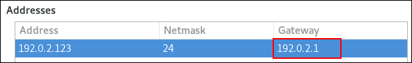
-
Open the
-
Set the IPv6 default gateway. For example, to set the IPv6 address of the default gateway on the connection to
2001:db8:1::1:-
Open the
IPv6tab. -
Enter the address in the
gatewayfield next to the IP range the gateway’s address is within: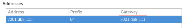
-
Open the
-
Click
.
-
Click
.
-
Restart the network connection for changes to take effect. For example, to restart the
exampleconnection using the command line:#
nmcli connection up
example
Warning
All connections currently using this network connection are temporarily interrupted during the restart.
-
Optionally, verify that the route is active.
To display the IPv4 default gateway:
#
ip -4 route
default via 192.0.2.1 devexample
proto static metric 100To display the IPv6 default gateway:
#
ip -6 route
default via 2001:db8:1::1 devexample
proto static metric 100 pref medium
Additional resources
- Configuring an Ethernet connection using nm-connection-editor
19.4. Setting the default gateway on an existing connection using control-center
In most situations, administrators set the default gateway when they create a connection. However, you can also set or update the default gateway setting on a previously created connection using the control-center application.
Prerequisites
- At least one static IP address must be configured on the connection on which the default gateway will be set.
-
The network configuration of the connection is open in the
control-centerapplication.
Procedure
-
Set the IPv4 default gateway. For example, to set the IPv4 address of the default gateway on the connection to
192.0.2.1:-
Open the
IPv4tab. -
Enter the address in the
gatewayfield next to the IP range the gateway’s address is within:
-
Open the
-
Set the IPv6 default gateway. For example, to set the IPv6 address of the default gateway on the connection to
2001:db8:1::1:-
Open the
IPv6tab. -
Enter the address in the
gatewayfield next to the IP range the gateway’s address is within: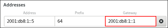
-
Open the
-
Click
.
-
Back in the
Networkwindow, disable and re-enable the connection by switching the button for the connection to Off and back to On for changes to take effect.Warning
All connections currently using this network connection are temporarily interrupted during the restart.
-
Optionally, verify that the route is active.
To display the IPv4 default gateway:
$
ip -4 route
default via 192.0.2.1 devexample
proto static metric 100To display the IPv6 default gateway:
$
ip -6 route
default via 2001:db8:1::1 devexample
proto static metric 100 pref medium
Additional resources
- Configuring an Ethernet connection using control-center
19.5. Setting the default gateway on an existing connection using nmstatectl
In most situations, administrators set the default gateway when they create a connection. However, you can also set or update the default gateway setting of a network connection using the nmstatectl utility.
Prerequisites
- At least one static IP address must be configured on the connection on which the default gateway will be set.
-
The
enp1s0interface is configured, and the IP address of the default gateway is within the subnet of the IP configuration of this interface. -
The
nmstatepackage is installed.
Procedure
-
Create a YAML file, for example
~/set-default-gateway.yml, with the following contents:--- routes: config: - destination: 0.0.0.0/0 next-hop-address: 192.0.2.1 next-hop-interface: enp1s0 -
Apply the settings to the system:
#
nmstatectl apply ~/set-default-gateway.yml
Additional resources
-
nmstatectl(8)man page -
/usr/share/doc/nmstate/examples/directory
19.6. Setting the default gateway on an existing connection using RHEL System Roles
You can use the network RHEL System Role to set the default gateway.
Important
When you run a play that uses the network RHEL System Role, the system role overrides an existing connection profile with the same name if the value of settings does not match the ones specified in the play. Therefore, always specify the whole configuration of the network connection profile in the play, even if, for example, the IP configuration already exists. Otherwise, the role resets these values to their defaults.
Depending on whether it already exists, the procedure creates or updates the enp1s0 connection profile with the following settings:
-
A static IPv4 address –
198.51.100.20with a/24subnet mask -
A static IPv6 address –
2001:db8:1::1with a/64subnet mask -
An IPv4 default gateway –
198.51.100.254 -
An IPv6 default gateway –
2001:db8:1::fffe -
An IPv4 DNS server –
198.51.100.200 -
An IPv6 DNS server –
2001:db8:1::ffbb -
A DNS search domain –
example.com
Perform this procedure on the Ansible control node.
Prerequisites
- You have prepared the control node and the managed nodes
- You are logged in to the control node as a user who can run playbooks on the managed nodes.
-
The account you use to connect to the managed nodes has
sudopermissions on them. - The hosts or host groups on which you want to run this playbook are listed in the Ansible inventory file.
Procedure
-
Create a playbook file, for example
~/ethernet-connection.yml, with the following content:--- - name: Configure the network hosts:
managed-node-01.example.com
tasks: - name: Configure an Ethernet connection with static IP and default gateway include_role: name: rhel-system-roles.network vars: network_connections: - name: enp1s0 type: ethernet autoconnect: yes ip: address: - 198.51.100.20/24 - 2001:db8:1::1/64 gateway4: 198.51.100.254 gateway6: 2001:db8:1::fffe dns: - 198.51.100.200 - 2001:db8:1::ffbb dns_search: - example.com state: up -
Run the playbook:
#
ansible-playbook
~/ethernet-connection.yml
Additional resources
-
/usr/share/ansible/roles/rhel-system-roles.network/README.mdfile
19.7. Setting the default gateway on an existing connection when using the legacy network scripts
In most situations, administrators set the default gateway when they create a connection. However, you can also set or update the default gateway setting on a previously created connection when you use the legacy network scripts.
Prerequisites
-
The
NetworkManagerpackage is not installed, or theNetworkManagerservice is disabled. -
The
network-scriptspackage is installed.
Procedure
-
Set the
GATEWAYparameter in the/etc/sysconfig/network-scripts/ifcfg-enp1s0file to192.0.2.1:GATEWAY=192.0.2.1
-
Add the
defaultentry in the/etc/sysconfig/network-scripts/route-enp0s1file:default via 192.0.2.1
-
Restart the network:
#
systemctl restart network
19.8. How NetworkManager manages multiple default gateways
In certain situations, for example for fallback reasons, you set multiple default gateways on a host. However, to avoid asynchronous routing issues, each default gateway of the same protocol requires a separate metric value. Note that RHEL only uses the connection to the default gateway that has the lowest metric set.
You can set the metric for both the IPv4 and IPv6 gateway of a connection using the following command:
#nmcli connection modify
connection-name
ipv4.route-metricvalue
ipv6.route-metricvalue
Important
Do not set the same metric value for the same protocol in multiple connection profiles to avoid routing issues.
If you set a default gateway without a metric value, NetworkManager automatically sets the metric value based on the interface type. For that, NetworkManager assigns the default value of this network type to the first connection that is activated, and sets an incremented value to each other connection of the same type in the order they are activated. For example, if two Ethernet connections with a default gateway exist, NetworkManager sets a metric of 100 on the route to the default gateway of the connection that you activate first. For the second connection, NetworkManager sets 101.
The following is an overview of frequently-used network types and their default metrics:
Connection typeDefault metric value
VPN
50
Ethernet
100
MACsec
125
InfiniBand
150
Bond
300
Team
350
VLAN
400
Bridge
425
TUN
450
Wi-Fi
600
IP tunnel
675
Additional resources
- Configuring policy-based routing to define alternative routes
- Getting started with Multipath TCP
19.9. Configuring NetworkManager to avoid using a specific profile to provide a default gateway
You can configure that NetworkManager never uses a specific profile to provide the default gateway. Follow this procedure for connection profiles that are not connected to the default gateway.
Prerequisites
- The NetworkManager connection profile for the connection that is not connected to the default gateway exists.
Procedure
-
If the connection uses a dynamic IP configuration, configure that NetworkManager does not use the connection as the default route for IPv4 and IPv6 connections:
#
nmcli connection modify
connection_name
ipv4.never-default yes ipv6.never-default yesNote that setting
ipv4.never-defaultandipv6.never-defaulttoyes, automatically removes the default gateway’s IP address for the corresponding protocol from the connection profile. -
Activate the connection:
#
nmcli connection up
connection_name
Verification steps
-
Use the
ip -4 routeandip -6 routecommands to verify that RHEL does not use the network interface for the default route for the IPv4 and IPv6 protocol.
19.10. Fixing unexpected routing behavior due to multiple default gateways
There are only a few scenarios, such as when using multipath TCP, in which you require multiple default gateways on a host. In most cases, you configure only a single default gateway to avoid unexpected routing behavior or asynchronous routing issues.
Note
To route traffic to different internet providers, use policy-based routing instead of multiple default gateways.
Prerequisites
- The host uses NetworkManager to manage network connections, which is the default.
- The host has multiple network interfaces.
- The host has multiple default gateways configured.
Procedure
-
Display the routing table:
-
For IPv4, enter:
#
ip -4 route
default via 192.0.2.1 dev enp1s0 proto static metric 101 default via 198.51.100.1 dev enp7s0 proto static metric 102 ... -
For IPv6, enter:
#
ip -6 route
default via 2001:db8:1::1 dev enp1s0 proto static metric 101 pref medium default via 2001:db8:2::1 dev enp7s0 proto static metric 102 pref medium ...
Entries starting with
defaultindicate a default route. Note the interface names of these entries displayed next todev. -
-
Use the following commands to display the NetworkManager connections that use the interfaces you identified in the previous step:
#
nmcli -f GENERAL.CONNECTION,IP4.GATEWAY,IP6.GATEWAY device show enp1s0
GENERAL.CONNECTION: Corporate-LAN IP4.GATEWAY: 192.168.122.1 IP6.GATEWAY: 2001:db8:1::1 #nmcli -f GENERAL.CONNECTION,IP4.GATEWAY,IP6.GATEWAY device show enp7s0
GENERAL.CONNECTION: Internet-Provider IP4.GATEWAY: 198.51.100.1 IP6.GATEWAY: 2001:db8:2::1In these examples, the profiles named
Corporate-LANandInternet-Providerhave the default gateways set. Because, in a local network, the default gateway is typically the host that is one hop closer to the internet, the rest of this procedure assumes that the default gateways in theCorporate-LANare incorrect. -
Configure that NetworkManager does not use the
Corporate-LANconnection as the default route for IPv4 and IPv6 connections:#
nmcli connection modify Corporate-LAN ipv4.never-default yes ipv6.never-default yes
Note that setting
ipv4.never-defaultandipv6.never-defaulttoyes, automatically removes the default gateway’s IP address for the corresponding protocol from the connection profile. -
Activate the
Corporate-LANconnection:#
nmcli connection up Corporate-LAN
Verification steps
-
Display the IPv4 and IPv6 routing tables and verify that only one default gateway is available for each protocol:
-
For IPv4, enter:
#
ip -4 route
default via 192.0.2.1 dev enp1s0 proto static metric 101 ... -
For IPv6, enter:
#
ip -6 route
default via 2001:db8:1::1 dev enp1s0 proto static metric 101 pref medium ...
-
Additional resources
- Configuring policy-based routing to define alternative routes
- Getting started with Multipath TCP
Chapter 20. Configuring static routes
Routing ensures that you can send and receive traffic between mutually-connected networks. In larger environments, administrators typically configure services so that routers can dynamically learn about other routers. In smaller environments, administrators often configure static routes to ensure that traffic can reach from one network to the next.
You need static routes to achieve a functioning communication among multiple networks if all of these conditions apply:
- The traffic has to pass multiple networks.
- The exclusive traffic flow through the default gateways is not sufficient.
Section 20.1, “Example of a network that requires static routes” describes scenarios and how the traffic flows between different networks when you do not configure static routes.
20.1. Example of a network that requires static routes
You require static routes in this example because not all IP networks are directly connected through one router. Without the static routes, some networks cannot communicate with each other. Additionally, traffic from some networks flows only in one direction.
Note
The network topology in this example is artificial and only used to explain the concept of static routing. It is not a recommended topology in production environments.
For a functioning communication among all networks in this example, configure a static route to Raleigh (198.51.100.0/24) with next the hop Router 2 (203.0.113.10). The IP address of the next hop is the one of Router 2 in the data center network (203.0.113.0/24).
You can configure the static route as follows:
-
For a simplified configuration, set this static route only on Router 1. However, this increases the traffic on Router 1 because hosts from the data center (
203.0.113.0/24) send traffic to Raleigh (198.51.100.0/24) always through Router 1 to Router 2. -
For a more complex configuration, configure this static route on all hosts in the data center (
203.0.113.0/24). All hosts in this subnet then send traffic directly to Router 2 (203.0.113.10) that is closer to Raleigh (198.51.100.0/24).
For more details between which networks traffic flows or not, see the explanations below the diagram.
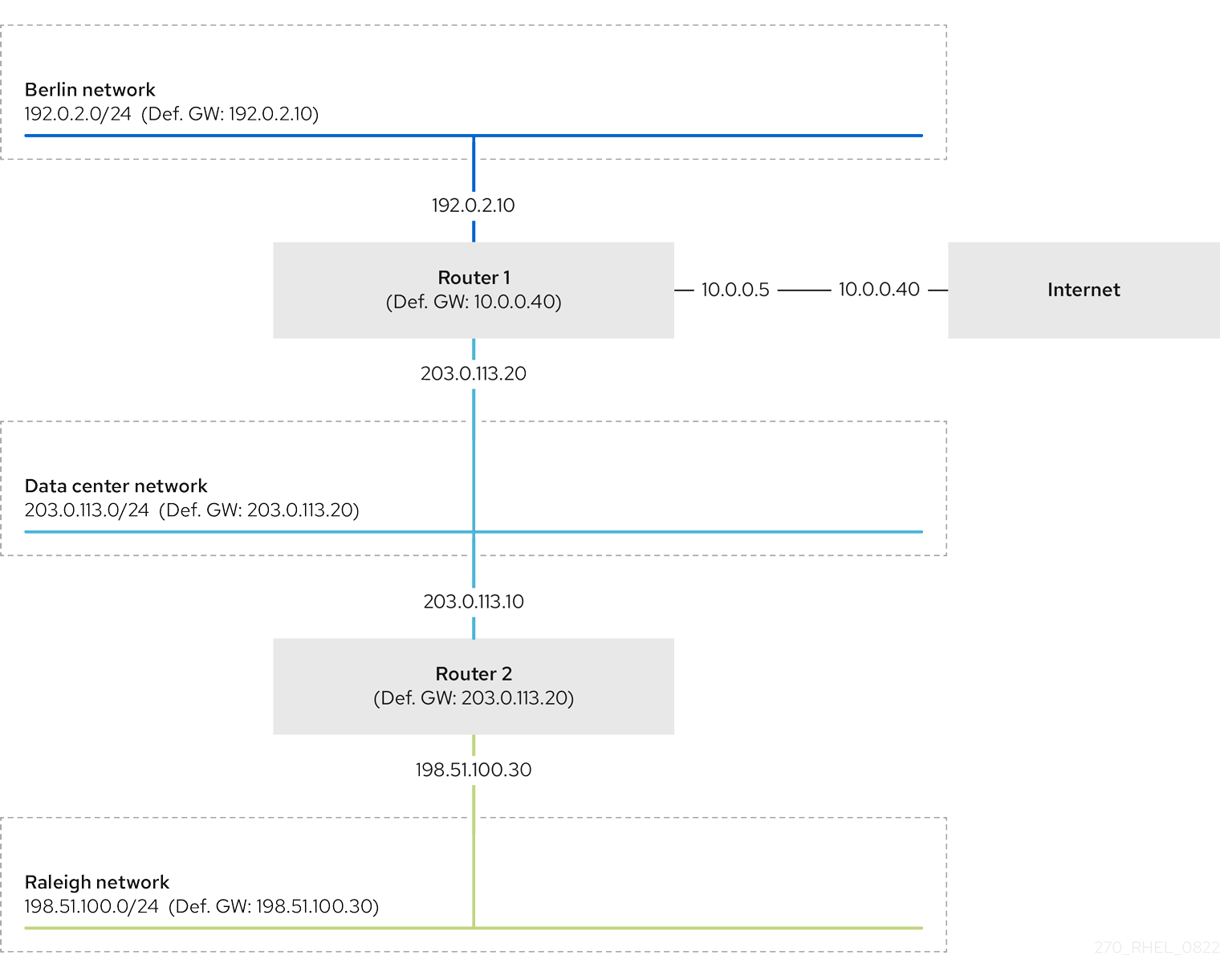
In case that the required static routes are not configured, the following are the situations in which the communication works and when it does not:
-
Hosts in the Berlin network (
192.0.2.0/24):- Can communicate with other hosts in the same subnet because they are directly connected.
-
Can communicate with the Internet because Router 1 is in the Berlin network (
192.0.2.0/24) and has a default gateway, which leads to the Internet. -
Can communicate with the data center network (
203.0.113.0/24) because Router 1 has interfaces in both the Berlin (192.0.2.0/24) and the data center (203.0.113.0/24) networks. -
Cannot communicate with the Raleigh network (
198.51.100.0/24) because Router 1 has no interface in this network. Therefore, Router 1 sends the traffic to its own default gateway (Internet).
-
Hosts in the data center network (
203.0.113.0/24):- Can communicate with other hosts in the same subnet because they are directly connected.
-
Can communicate with the Internet because they have their default gateway set to Router 1, and Router 1 has interfaces in both networks, the data center (
203.0.113.0/24) and to the Internet. -
Can communicate with the Berlin network (
192.0.2.0/24) because they have their default gateway set to Router 1, and Router 1 has interfaces in both the data center (203.0.113.0/24) and the Berlin (192.0.2.0/24) networks. -
Cannot communicate with the Raleigh network (
198.51.100.0/24) because the data center network has no interface in this network. Therefore, hosts in the data center (203.0.113.0/24) send traffic to their default gateway (Router 1). Router 1 also has no interface in the Raleigh network (198.51.100.0/24) and, as a result, Router 1 sends this traffic to its own default gateway (Internet).
-
Hosts in the Raleigh network (
198.51.100.0/24):- Can communicate with other hosts in the same subnet because they are directly connected.
-
Cannot communicate with hosts on the Internet. Router 2 sends the traffic to Router 1 because of the default gateway settings. The actual behavior of Router 1 depends on the reverse path filter (
rp_filter) system control (sysctl) setting. By default on RHEL, Router 1 drops the outgoing traffic instead of routing it to the Internet. However, regardless of the configured behavior, communication is not possible without the static route. -
Cannot communicate with the data center network (
203.0.113.0/24). The outgoing traffic reaches the destination through Router 2 because of the default gateway setting. However, replies to packets do not reach the sender because hosts in the data center network (203.0.113.0/24) send replies to their default gateway (Router 1). Router 1 then sends the traffic to the Internet. -
Cannot communicate with the Berlin network (
192.0.2.0/24). Router 2 sends the traffic to Router 1 because of the default gateway settings. The actual behavior of Router 1 depends on therp_filtersysctlsetting. By default on RHEL, Router 1 drops the outgoing traffic instead of sending it to the Berlin network (192.0.2.0/24). However, regardless of the configured behavior, communication is not possible without the static route.
Note
In addition to configuring the static routes, you must enable IP forwarding on both routers.
Additional resources
- Why can’t a server be pinged if net.ipv4.conf.all.rp_filter is set on the server?
- Enabling IP forwarding
20.2. How to use the nmcli command to configure a static route
To configure a static route, use the nmcli utility with the following syntax:
$nmcli connection modify
connection_name
ipv4.routes "ip
[/prefix
] [next_hop
] [metric
] [attribute
=value
] [attribute
=value
] ..."
The command supports the following route attributes:
-
cwnd=: Sets the congestion window (CWND) size, defined in number of packets.n
-
lock-cwnd=true|false: Defines whether or not the kernel can update the CWND value. -
lock-mtu=true|false: Defines whether or not the kernel can update the MTU to path MTU discovery. -
lock-window=true|false: Defines whether or not the kernel can update the maximum window size for TCP packets. -
mtu=: Sets the maximum transfer unit (MTU) to use along the path to the destination.n
-
onlink=true|false: Defines whether the next hop is directly attached to this link even if it does not match any interface prefix. -
scope=: For an IPv4 route, this attribute sets the scope of the destinations covered by the route prefix. Set the value as an integer (0-255).n
-
src=: Sets the source address to prefer when sending traffic to the destinations covered by the route prefix.address
-
table=: Sets the ID of the table the route should be added to. If you omit this parameter, NetworkManager uses thetable_id
maintable. -
tos=: Sets the type of service (TOS) key. Set the value as an integer (0-255).n
-
type=: Sets the route type. NetworkManager supports thevalue
unicast,local,blackhole,unreachable,prohibit, andthrowroute types. The default isunicast. -
window=: Sets the maximal window size for TCP to advertise to these destinations, measured in bytes.n
If you use the ipv4.routes sub-command, nmcli overrides all current settings of this parameter.
To add a route:
$nmcli connection modify
connection_name
+ipv4.routes "..."
Similarly, to remove a specific route:
$nmcli connection modify
connection_name
-ipv4.routes "..."
20.3. Configuring a static route using an nmcli command
You can add a static route to an existing NetworkManager connection profile using the nmcli connection modify command.
The procedure below configures the following routes:
-
An IPv4 route to the remote
198.51.100.0/24network. The corresponding gateway with the IP address192.0.2.10is reachable through theexampleconnection. -
An IPv6 route to the remote
2001:db8:2::/64network. The corresponding gateway with the IP address2001:db8:1::10is reachable through theexampleconnection.
Prerequisites
-
The
exampleconnection profile exists and it configures this host to be in the same IP subnet as the gateways.
Procedure
-
Add the static IPv4 route to the
exampleconnection profile:#
nmcli connection modify
example
+ipv4.routes "198.51.100.0/24 192.0.2.10
"To set multiple routes in one step, pass the individual routes comma-separated to the command. For example, to add a route to the
198.51.100.0/24and203.0.113.0/24networks, both routed through the192.0.2.10gateway, enter:#
nmcli connection modify
example
+ipv4.routes "198.51.100.0/24 192.0.2.10
,203.0.113.0/24 192.0.2.10
" -
Add the static IPv6 route to the
exampleconnection profile:#
nmcli connection modify
example
+ipv6.routes "2001:db8:2::/64 2001:db8:1::10
" -
Re-activate the connection:
#
nmcli connection up
example
Verification
-
Display the IPv4 routes:
#
ip -4 route
...198.51.100.0/24
via192.0.2.10
devenp1s0
-
Display the IPv6 routes:
#
ip -6 route
...2001:db8:2::/64
via2001:db8:1::10
devenp1s0
metric1024
prefmedium
Additional resources
-
nmcli(1)man page -
nm-settings-nmcli(5)man page
20.4. Configuring a static route using nmtui
The nmtui application provides a text-based user interface for NetworkManager. You can use nmtui to configure static routes on a host without a graphical interface.
For example, the procedure below adds a route to the 192.0.2.0/24 network that uses the gateway running on 198.51.100.1, which is reachable through an existing connection profile.
Note
In nmtui:
- Navigate by using the cursor keys.
-
Press a button by selecting it and hitting
Enter
.
-
Select and deselect checkboxes by using
Space
.
Prerequisites
- The network is configured.
- The gateway for the static route must be directly reachable on the interface.
- If the user is logged in on a physical console, user permissions are sufficient. Otherwise, the command requires root permissions.
Procedure
-
Start
nmtui:#
nmtui
-
Select
Edit a connection, and pressEnter
.
-
Select the connection profile through which you can reach the next hop to the destination network, and press
Enter
.
-
Depending on whether it is an IPv4 or IPv6 route, press the
Showbutton next to the protocol’s configuration area. -
Press the
Editbutton next toRouting. This opens a new window where you configure static routes:-
Press the
Addbutton and fill in:- The destination network, including the prefix in Classless Inter-Domain Routing (CIDR) format
- The IP address of the next hop
- A metric value, if you add multiple routes to the same network and want to prioritize the routes by efficiency
- Repeat the previous step for every route you want to add and that is reachable through this connection profile.
-
Press the
OKbutton to return to the window with the connection settings.Figure 20.1. Example of a static route without metric

-
-
Press the
OKbutton to return to thenmtuimain menu. -
Select
Activate a connectionand pressEnter
.
-
Select the connection profile that you edited, and press Enter twice to deactivate and activate it again.
Important
Skip this step if you run
nmtuiover a remote connection, such as SSH, that uses the connection profile you want to reactivate. In this case, if you would deactivate it innmtui, the connection is terminated and, consequently, you cannot activate it again. To avoid this problem, use thenmcli connection connection_profile_name upcommand to reactivate the connection in the mentioned scenario. -
Press the
Backbutton to return to the main menu. -
Select
Quit, and pressEnter
to close the
nmtuiapplication.
Verification
-
Verify that the route is active:
$
ip route... 192.0.2.0/24 via 198.51.100.1 devexample
proto static metric 100
20.5. Configuring a static route using control-center
You can use control-center in GNOME to add a static route to the configuration of a network connection.
The procedure below configures the following routes:
-
An IPv4 route to the remote
198.51.100.0/24network. The corresponding gateway has the IP address192.0.2.10. -
An IPv6 route to the remote
2001:db8:2::/64network. The corresponding gateway has the IP address2001:db8:1::10.
Prerequisites
- The network is configured.
- This host is in the same IP subnet as the gateways.
-
The network configuration of the connection is opened in the
control-centerapplication. See Configuring an Ethernet connection using nm-connection-editor.
Procedure
-
On the
IPv4tab:-
Optional: Disable automatic routes by clicking the
button in the
Routessection of theIPv4tab to use only static routes. If automatic routes are enabled, Red Hat Enterprise Linux uses static routes and routes received from a DHCP server. -
Enter the address, netmask, gateway, and optionally a metric value of the IPv4 route:
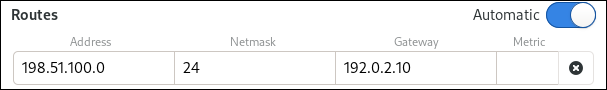
-
Optional: Disable automatic routes by clicking the
-
On the
IPv6tab:-
Optional: Disable automatic routes by clicking the
button i the
Routessection of theIPv4tab to use only static routes. -
Enter the address, netmask, gateway, and optionally a metric value of the IPv6 route:
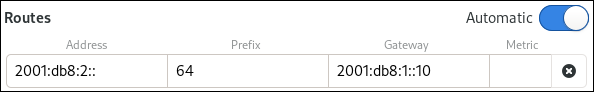
-
Optional: Disable automatic routes by clicking the
-
Click
.
-
Back in the
Networkwindow, disable and re-enable the connection by switching the button for the connection to Off and back to On for changes to take effect.Warning
Restarting the connection briefly disrupts connectivity on that interface.
Verification
-
Display the IPv4 routes:
#
ip -4 route
...198.51.100.0/24
via192.0.2.10
devenp1s0
-
Display the IPv6 routes:
#
ip -6 route
...2001:db8:2::/64
via2001:db8:1::10
devenp1s0
metric1024
prefmedium
20.6. Configuring a static route using nm-connection-editor
You can use the nm-connection-editor application to add a static route to the configuration of a network connection.
The procedure below configures the following routes:
-
An IPv4 route to the remote
198.51.100.0/24network. The corresponding gateway with the IP address192.0.2.10is reachable through theexampleconnection. -
An IPv6 route to the remote
2001:db8:2::/64network. The corresponding gateway with the IP address2001:db8:1::10is reachable through theexampleconnection.
Prerequisites
- The network is configured.
- This host is in the same IP subnet as the gateways.
Procedure
-
Open a terminal, and enter
nm-connection-editor:$
nm-connection-editor -
Select the
exampleconnection profile, and click the gear wheel icon to edit the existing connection. -
On the
IPv4 Settingstab:-
Click the
button.
-
Click the Add button and enter the address, netmask, gateway, and optionally a metric value.

-
Click
.
-
Click the
-
On the
IPv6 Settingstab:-
Click the
button.
-
Click the Add button and enter the address, netmask, gateway, and optionally a metric value.
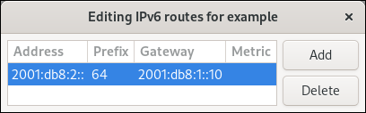
-
Click
.
-
Click the
-
Click
.
-
Restart the network connection for changes to take effect. For example, to restart the
exampleconnection using the command line:#
nmcli connection up
example
Verification
-
Display the IPv4 routes:
#
ip -4 route
...198.51.100.0/24
via192.0.2.10
devenp1s0
-
Display the IPv6 routes:
#
ip -6 route
...2001:db8:2::/64
via2001:db8:1::10
devenp1s0
metric1024
prefmedium
20.7. Configuring a static route using the nmcli interactive mode
You can use the interactive mode of the nmcli utility to add a static route to the configuration of a network connection.
The procedure below configures the following routes:
-
An IPv4 route to the remote
198.51.100.0/24network. The corresponding gateway with the IP address192.0.2.10is reachable through theexampleconnection. -
An IPv6 route to the remote
2001:db8:2::/64network. The corresponding gateway with the IP address2001:db8:1::10is reachable through theexampleconnection.
Prerequisites
-
The
exampleconnection profile exists and it configures this host to be in the same IP subnet as the gateways.
Procedure
-
Open the
nmcliinteractive mode for theexampleconnection:#
nmcli connection edit
example
-
Add the static IPv4 route:
nmcli>
set ipv4.routes
198.51.100.0/24 192.0.2.10
-
Add the static IPv6 route:
nmcli>
set ipv6.routes
2001:db8:2::/64 2001:db8:1::10
-
Optionally, verify that the routes were added correctly to the configuration:
nmcli>
print
... ipv4.routes: { ip =198.51.100.0/24
, nh =192.0.2.10
} ... ipv6.routes: { ip =2001:db8:2::/64
, nh =2001:db8:1::10
} ...The
ipattribute displays the network to route and thenhattribute the gateway (next hop). -
Save the configuration:
nmcli>
save persistent
-
Restart the network connection:
nmcli>
activate
example
-
Leave the
nmcliinteractive mode:nmcli>
quit
Verification
-
Display the IPv4 routes:
#
ip -4 route
...198.51.100.0/24
via192.0.2.10
devenp1s0
-
Display the IPv6 routes:
#
ip -6 route
...2001:db8:2::/64
via2001:db8:1::10
devenp1s0
metric1024
prefmedium
Additional resources
-
nmcli(1)man page -
nm-settings-nmcli(5)man page
20.8. Configuring a static route using nmstatectl
You can add a static route to the configuration of a network connection using the nmstatectl utility.
The procedure below configures the following routes:
-
An IPv4 route to the remote
198.51.100.0/24network. The corresponding gateway with the IP address192.0.2.10is reachable through theenp1s0interface. -
An IPv6 route to the remote
2001:db8:2::/64network. The corresponding gateway with the IP address2001:db8:1::10is reachable through theenp1s0interface.
Prerequisites
-
The
enp1s0network interface is configured and is in the same IP subnet as the gateways. -
The
nmstatepackage is installed.
Procedure
-
Create a YAML file, for example
~/add-static-route-to-enp1s0.yml, with the following contents:---
routes:
config:
- destination:
198.51.100.0/24
next-hop-address:
192.0.2.10
next-hop-interface:
enp1s0
- destination:
2001:db8:2::/64
next-hop-address:
2001:db8:1::10
next-hop-interface:
enp1s0
-
Apply the settings to the system:
#
nmstatectl apply
~/add-static-route-to-enp1s0.yml
Verification
-
Display the IPv4 routes:
#
ip -4 route
...198.51.100.0/24
via192.0.2.10
devenp1s0
-
Display the IPv6 routes:
#
ip -6 route
...2001:db8:2::/64
via2001:db8:1::10
devenp1s0
metric1024
prefmedium
Additional resources
-
nmstatectl(8)man page -
/usr/share/doc/nmstate/examples/directory
20.9. Configuring a static route using RHEL System Roles
You can use the network RHEL System Role to configure static routes.
Important
When you run a play that uses the network RHEL System Role, the system role overrides an existing connection profile with the same name if the value of settings does not match the ones specified in the play. Therefore, always specify the whole configuration of the network connection profile in the play, even if, for example, the IP configuration already exists. Otherwise, the role resets these values to their defaults.
Depending on whether it already exists, the procedure creates or updates the enp7s0 connection profile with the following settings:
-
A static IPv4 address –
192.0.2.1with a/24subnet mask -
A static IPv6 address –
2001:db8:1::1with a/64subnet mask -
An IPv4 default gateway –
192.0.2.254 -
An IPv6 default gateway –
2001:db8:1::fffe -
An IPv4 DNS server –
192.0.2.200 -
An IPv6 DNS server –
2001:db8:1::ffbb -
A DNS search domain –
example.com -
Static routes:
-
198.51.100.0/24with gateway192.0.2.10 -
2001:db8:2::/64with gateway2001:db8:1::10
-
Perform this procedure on the Ansible control node.
Prerequisites
- You have prepared the control node and the managed nodes
- You are logged in to the control node as a user who can run playbooks on the managed nodes.
-
The account you use to connect to the managed nodes has
sudopermissions on them. - The hosts or host groups on which you to want run this playbook are listed in the Ansible inventory file.
Procedure
-
Create a playbook file, for example
~/add-static-routes.yml, with the following content:--- - name: Configure the network hosts:
managed-node-01.example.com
tasks: - name:Configure an Ethernet connection with static IP and additional routes
include_role: name: rhel-system-roles.network vars: network_connections: - name:enp7s0
type:ethernet
autoconnect:yes
ip: address: -192.0.2.1/24
-2001:db8:1::1/64
gateway4:192.0.2.254
gateway6:2001:db8:1::fffe
dns: -192.0.2.200
-2001:db8:1::ffbb
dns_search: -example.com
route: - network:198.51.100.0
prefix:24
gateway:192.0.2.10
- network:2001:db8:2::
prefix:64
gateway:2001:db8:1::10
state:up
-
Run the playbook:
#
ansible-playbook
~/add-static-routes.yml
Verification steps
-
On the managed nodes:
-
Display the IPv4 routes:
#
ip -4 route
...198.51.100.0/24
via192.0.2.10
devenp7s0
-
Display the IPv6 routes:
#
ip -6 route
...2001:db8:2::/64
via2001:db8:1::10
devenp7s0
metric1024
prefmedium
-
Additional resources
-
/usr/share/ansible/roles/rhel-system-roles.network/README.mdfile
20.10. Creating static routes configuration files in key-value format when using the legacy network scripts
The legacy network scripts support setting statics routes in key-value format.
The procedure below configures an IPv4 route to the remote 198.51.100.0/24 network. The corresponding gateway with the IP address 192.0.2.10 is reachable through the enp1s0 interface.
Note
The legacy network scripts support the key-value format only for static IPv4 routes. For IPv6 routes, use the ip-command format. See Creating static routes configuration files in ip-command format when using the legacy network scripts.
Prerequisites
- The gateways for the static route must be directly reachable on the interface.
-
The
NetworkManagerpackage is not installed, or theNetworkManagerservice is disabled. -
The
network-scriptspackage is installed. -
The
networkservice is enabled.
Procedure
-
Add the static IPv4 route to the
/etc/sysconfig/network-scripts/route-enp0s1file:ADDRESS0=
198.51.100.0
NETMASK0=255.255.255.0
GATEWAY0=192.0.2.10
-
The
ADDRESS0variable defines the network of the first routing entry. -
The
NETMASK0variable defines the netmask of the first routing entry. -
The
GATEWAY0variable defines the IP address of the gateway to the remote network or host for the first routing entry.If you add multiple static routes, increase the number in the variable names. Note that the variables for each route must be numbered sequentially. For example,
ADDRESS0,ADDRESS1,ADDRESS3, and so on.
-
The
-
Restart the network:
#
systemctl restart network
Verification
-
Display the IPv4 routes:
#
ip -4 route
...198.51.100.0/24
via192.0.2.10
devenp1s0
Troubleshooting
-
Display the journal entries of the
networkunit:#
journalctl -u network
The following are possible error messages and their causes:
-
Error: Nexthop has invalid gateway: You specified an IPv4 gateway address in theroute-file that is not in the same subnet as this router.enp1s0
-
RTNETLINK answers: No route to host: You specified an IPv6 gateway address in theroute6-file that is not in the same subnet as this router.enp1s0
-
Error: Invalid prefix for given prefix length: You specified the remote network in theroute-file by using an IP address within the remote network rather than the network address.enp1s0
-
Additional resources
-
/usr/share/doc/network-scripts/sysconfig.txtfile
20.11. Creating static routes configuration files in ip-command format when using the legacy network scripts
The legacy network scripts support setting statics routes.
The procedure below configures the following routes:
-
An IPv4 route to the remote
198.51.100.0/24network. The corresponding gateway with the IP address192.0.2.10is reachable through theenp1s0interface. -
An IPv6 route to the remote
2001:db8:2::/64network. The corresponding gateway with the IP address2001:db8:1::10is reachable through theenp1s0interface.
Important
IP addresses of the gateways (next hop) must be in the same IP subnet as the host on which you configure the static routes.
The examples in this procedure use configuration entries in ip-command format.
Prerequisites
- The gateways for the static route must be directly reachable on the interface.
-
The
NetworkManagerpackage is not installed, or theNetworkManagerservice is disabled. -
The
network-scriptspackage is installed. -
The
networkservice is enabled.
Procedure
-
Add the static IPv4 route to the
/etc/sysconfig/network-scripts/route-enp1s0file:198.51.100.0/24 via 192.0.2.10 dev enp1s0
Always specify the network address of the remote network, such as
198.51.100.0. Setting an IP address within the remote network, such as198.51.100.1causes that the network scripts fail to add this route. -
Add the static IPv6 route to the
/etc/sysconfig/network-scripts/route6-enp1s0file:2001:db8:2::/64 via 2001:db8:1::10 dev enp1s0
-
Restart the
networkservice:#
systemctl restart network
Verification
-
Display the IPv4 routes:
#
ip -4 route
...198.51.100.0/24
via192.0.2.10
devenp1s0
-
Display the IPv6 routes:
#
ip -6 route
...2001:db8:2::/64
via2001:db8:1::10
devenp1s0
metric1024
prefmedium
Troubleshooting
-
Display the journal entries of the
networkunit:#
journalctl -u network
The following are possible error messages and their causes:
-
Error: Nexthop has invalid gateway: You specified an IPv4 gateway address in theroute-file that is not in the same subnet as this router.enp1s0
-
RTNETLINK answers: No route to host: You specified an IPv6 gateway address in theroute6-file that is not in the same subnet as this router.enp1s0
-
Error: Invalid prefix for given prefix length: You specified the remote network in theroute-file by using an IP address within the remote network rather than the network address.enp1s0
-
Additional Resources
-
/usr/share/doc/network-scripts/sysconfig.txtfile
Chapter 21. Configuring policy-based routing to define alternative routes
By default, the kernel in RHEL decides where to forward network packets based on the destination address using a routing table. Policy-based routing enables you to configure complex routing scenarios. For example, you can route packets based on various criteria, such as the source address, packet metadata, or protocol.
Note
On systems that use NetworkManager, only the nmcli utility supports setting routing rules and assigning routes to specific tables.
21.1. Routing traffic from a specific subnet to a different default gateway using NetworkManager
You can use policy-based routing to configure a different default gateway for traffic from certain subnets. For example, you can configure RHEL as a router that, by default, routes all traffic to Internet provider A using the default route. However, traffic received from the internal workstations subnet is routed to provider B.
The procedure assumes the following network topology:

Prerequisites
-
The system uses
NetworkManagerto configure the network, which is the default. -
The RHEL router you want to set up in the procedure has four network interfaces:
-
The
enp7s0interface is connected to the network of provider A. The gateway IP in the provider’s network is198.51.100.2, and the network uses a/30network mask. -
The
enp1s0interface is connected to the network of provider B. The gateway IP in the provider’s network is192.0.2.2, and the network uses a/30network mask. -
The
enp8s0interface is connected to the10.0.0.0/24subnet with internal workstations. -
The
enp9s0interface is connected to the203.0.113.0/24subnet with the company’s servers.
-
The
-
Hosts in the internal workstations subnet use
10.0.0.1as the default gateway. In the procedure, you assign this IP address to theenp8s0network interface of the router. -
Hosts in the server subnet use
203.0.113.1as the default gateway. In the procedure, you assign this IP address to theenp9s0network interface of the router. -
The
firewalldservice is enabled and active.
Procedure
-
Configure the network interface to provider A:
#
nmcli connection add type ethernet con-name Provider-A ifname enp7s0 ipv4.method manual ipv4.addresses 198.51.100.1/30 ipv4.gateway 198.51.100.2 ipv4.dns 198.51.100.200 connection.zone external
The
nmcli connection addcommand creates a NetworkManager connection profile. The command uses the following options:-
typeethernet: Defines that the connection type is Ethernet. -
con-nameconnection_name
-
ifnamenetwork_device
-
ipv4.methodmanual: Enables to configure a static IP address. -
ipv4.addressesIP_address
/
subnet_mask
-
ipv4.gatewayIP_address
-
ipv4.dnsIP_of_DNS_server
-
connection.zonefirewalld_zone
firewalldzone. Note thatfirewalldautomatically enables masquerading for interfaces assigned to theexternalzone.
-
-
Configure the network interface to provider B:
#
nmcli connection add type ethernet con-name Provider-B ifname enp1s0 ipv4.method manual ipv4.addresses 192.0.2.1/30 ipv4.routes "0.0.0.0/0 192.0.2.2 table=5000" connection.zone external
This command uses the
ipv4.routesparameter instead ofipv4.gatewayto set the default gateway. This is required to assign the default gateway for this connection to a different routing table (5000) than the default. NetworkManager automatically creates this new routing table when the connection is activated. -
Configure the network interface to the internal workstations subnet:
#
nmcli connection add type ethernet con-name Internal-Workstations ifname enp8s0 ipv4.method manual ipv4.addresses 10.0.0.1/24 ipv4.routes "10.0.0.0/24 table=5000" ipv4.routing-rules "priority 5 from 10.0.0.0/24 table 5000" connection.zone trusted
This command uses the
ipv4.routesparameter to add a static route to the routing table with ID5000. This static route for the10.0.0.0/24subnet uses the IP of the local network interface to provider B (192.0.2.1) as next hop.Additionally, the command uses the
ipv4.routing-rulesparameter to add a routing rule with priority5that routes traffic from the10.0.0.0/24subnet to table5000. Low values have a high priority.Note that the syntax in the
ipv4.routing-rulesparameter is the same as in anip rule addcommand, except thatipv4.routing-rulesalways requires specifying a priority. -
Configure the network interface to the server subnet:
#
nmcli connection add type ethernet con-name Servers ifname enp9s0 ipv4.method manual ipv4.addresses 203.0.113.1/24 connection.zone trusted
Verification steps
-
On a RHEL host in the internal workstation subnet:
-
Install the
traceroutepackage:#
yum install traceroute
-
Use the
tracerouteutility to display the route to a host on the Internet:#
traceroute redhat.com
traceroute to redhat.com (209.132.183.105), 30 hops max, 60 byte packets 1 10.0.0.1 (10.0.0.1) 0.337 ms 0.260 ms 0.223 ms 2 192.0.2.1 (192.0.2.1) 0.884 ms 1.066 ms 1.248 ms ...The output of the command displays that the router sends packets over
192.0.2.1, which is the network of provider B.
-
-
On a RHEL host in the server subnet:
-
Install the
traceroutepackage:#
yum install traceroute
-
Use the
tracerouteutility to display the route to a host on the Internet:#
traceroute redhat.com
traceroute to redhat.com (209.132.183.105), 30 hops max, 60 byte packets 1 203.0.113.1 (203.0.113.1) 2.179 ms 2.073 ms 1.944 ms 2 198.51.100.2 (198.51.100.2) 1.868 ms 1.798 ms 1.549 ms ...The output of the command displays that the router sends packets over
198.51.100.2, which is the network of provider A.
-
Troubleshooting steps
On the RHEL router:
-
Display the rule list:
#
ip rule list
0: from all lookup local5
:from 10.0.0.0/24 lookup 5000
32766: from all lookup main 32767: from all lookup defaultBy default, RHEL contains rules for the tables
local,main, anddefault. -
Display the routes in table
5000:#
ip route list table 5000
0.0.0.0/0 via 192.0.2.2 dev enp1s0 proto static metric 100 10.0.0.0/24 dev enp8s0 proto static scope link src 192.0.2.1 metric 102 -
Display the interfaces and firewall zones:
#
firewall-cmd --get-active-zones
external interfaces: enp1s0 enp7s0 trusted interfaces: enp8s0 enp9s0 -
Verify that the
externalzone has masquerading enabled:#
firewall-cmd --info-zone=external
external (active) target: default icmp-block-inversion: no interfaces: enp1s0 enp7s0 sources: services: ssh ports: protocols:masquerade: yes
...
Additional resources
-
nm-settings(5)man page -
nmcli(1)man page - Is it possible to set up Policy Based Routing with NetworkManager in RHEL?
21.2. Routing traffic from a specific subnet to a different default gateway using RHEL System Roles
You can use policy-based routing to configure a different default gateway for traffic from certain subnets. For example, you can configure RHEL as a router that, by default, routes all traffic to Internet provider A using the default route. However, traffic received from the internal workstations subnet is routed to provider B.
To configure policy-based routing remotely and on multiple nodes, you can use the RHEL network System Role. Perform this procedure on the Ansible control node.
This procedure assumes the following network topology:
Prerequisites
- You have prepared the control node and the managed nodes
- You are logged in to the control node as a user who can run playbooks on the managed nodes.
-
The account you use to connect to the managed nodes has
sudopermissions on the them. - The hosts or host groups on which you want run this playbook are listed in the Ansible inventory file.
-
The managed nodes uses the
NetworkManagerandfirewalldservices. -
The managed nodes you want to configure has four network interfaces:
-
The
enp7s0interface is connected to the network of provider A. The gateway IP in the provider’s network is198.51.100.2, and the network uses a/30network mask. -
The
enp1s0interface is connected to the network of provider B. The gateway IP in the provider’s network is192.0.2.2, and the network uses a/30network mask. -
The
enp8s0interface is connected to the10.0.0.0/24subnet with internal workstations. -
The
enp9s0interface is connected to the203.0.113.0/24subnet with the company’s servers.
-
The
-
Hosts in the internal workstations subnet use
10.0.0.1as the default gateway. In the procedure, you assign this IP address to theenp8s0network interface of the router. -
Hosts in the server subnet use
203.0.113.1as the default gateway. In the procedure, you assign this IP address to theenp9s0network interface of the router.
Procedure
-
Create a playbook file, for example
~/pbr.yml, with the following content:--- - name: Configuring policy-based routing hosts:
managed-node-01.example.com
tasks: - name: Routing traffic from a specific subnet to a different default gateway include_role: name: rhel-system-roles.network vars: network_connections: - name: Provider-A interface_name: enp7s0 type: ethernet autoconnect: True ip: address: - 198.51.100.1/30 gateway4: 198.51.100.2 dns: - 198.51.100.200 state: up zone: external - name: Provider-B interface_name: enp1s0 type: ethernet autoconnect: True ip: address: - 192.0.2.1/30 route: - network: 0.0.0.0 prefix: 0 gateway: 192.0.2.2 table: 5000 state: up zone: external - name: Internal-Workstations interface_name: enp8s0 type: ethernet autoconnect: True ip: address: - 10.0.0.1/24 route: - network: 10.0.0.0 prefix: 24 table: 5000 routing_rule: - priority: 5 from: 10.0.0.0/24 table: 5000 state: up zone: trusted - name: Servers interface_name: enp9s0 type: ethernet autoconnect: True ip: address: - 203.0.113.1/24 state: up zone: trusted -
Run the playbook:
#
ansible-playbook
~/pbr.yml
Verification
-
On a RHEL host in the internal workstation subnet:
-
Install the
traceroutepackage:#
yum install traceroute
-
Use the
tracerouteutility to display the route to a host on the Internet:#
traceroute redhat.com
traceroute to redhat.com (209.132.183.105), 30 hops max, 60 byte packets 1 10.0.0.1 (10.0.0.1) 0.337 ms 0.260 ms 0.223 ms 2 192.0.2.1 (192.0.2.1) 0.884 ms 1.066 ms 1.248 ms ...The output of the command displays that the router sends packets over
192.0.2.1, which is the network of provider B.
-
-
On a RHEL host in the server subnet:
-
Install the
traceroutepackage:#
yum install traceroute
-
Use the
tracerouteutility to display the route to a host on the Internet:#
traceroute redhat.com
traceroute to redhat.com (209.132.183.105), 30 hops max, 60 byte packets 1 203.0.113.1 (203.0.113.1) 2.179 ms 2.073 ms 1.944 ms 2 198.51.100.2 (198.51.100.2) 1.868 ms 1.798 ms 1.549 ms ...The output of the command displays that the router sends packets over
198.51.100.2, which is the network of provider A.
-
-
On the RHEL router that you configured using the RHEL System Role:
-
Display the rule list:
#
ip rule list
0: from all lookup local5
:from 10.0.0.0/24 lookup 5000
32766: from all lookup main 32767: from all lookup defaultBy default, RHEL contains rules for the tables
local,main, anddefault. -
Display the routes in table
5000:#
ip route list table 5000
0.0.0.0/0 via 192.0.2.2 dev enp1s0 proto static metric 100 10.0.0.0/24 dev enp8s0 proto static scope link src 192.0.2.1 metric 102 -
Display the interfaces and firewall zones:
#
firewall-cmd --get-active-zones
external interfaces: enp1s0 enp7s0 trusted interfaces: enp8s0 enp9s0 -
Verify that the
externalzone has masquerading enabled:#
firewall-cmd --info-zone=external
external (active) target: default icmp-block-inversion: no interfaces: enp1s0 enp7s0 sources: services: ssh ports: protocols:masquerade: yes
...
-
Additional resources
-
/usr/share/ansible/roles/rhel-system-roles.network/README.mdfile
21.3. Overview of configuration files involved in policy-based routing when using the legacy network scripts
If you use the legacy network scripts instead of NetworkManager to configure your network, you can also configure policy-based routing.
Note
Configuring the network using the legacy network scripts provided by the network-scripts package is deprecated in RHEL 8. Red Hat recommends that you use NetworkManager to configure policy-based routing. For an example, see Routing traffic from a specific subnet to a different default gateway using NetworkManager.
The following configuration files are involved in policy-based routing when you use the legacy network scripts:
-
/etc/sysconfig/network-scripts/route-interface: This file defines the IPv4 routes. Use thetableoption to specify the routing table. For example:192.0.2.0/24 via 198.51.100.1
table 1
203.0.113.0/24 via 198.51.100.2table 2
-
/etc/sysconfig/network-scripts/route6-: This file defines the IPv6 routes.interface
-
/etc/sysconfig/network-scripts/rule-interface: This file defines the rules for IPv4 source networks for which the kernel routes traffic to specific routing tables. For example:from 192.0.2.0/24 lookup 1 from 203.0.113.0/24 lookup 2
-
/etc/sysconfig/network-scripts/rule6-: This file defines the rules for IPv6 source networks for which the kernel routes traffic to specific routing tables.interface
-
/etc/iproute2/rt_tables: This file defines the mappings if you want to use names instead of numbers to refer to specific routing tables. For example:1 Provider_A 2 Provider_B
Additional resources
-
ip-route(8)man page -
ip-rule(8)man page
21.4. Routing traffic from a specific subnet to a different default gateway using the legacy network scripts
You can use policy-based routing to configure a different default gateway for traffic from certain subnets. For example, you can configure RHEL as a router that, by default, routes all traffic to Internet provider A using the default route. However, traffic received from the internal workstations subnet is routed to provider B.
Important
Configuring the network using the legacy network scripts provided by the network-scripts package is deprecated in RHEL 8. Follow the procedure only if you use the legacy network scripts instead of NetworkManager on your host. If you use NetworkManager to manage your network settings, see Routing traffic from a specific subnet to a different default gateway using NetworkManager.
The procedure assumes the following network topology:
Note
The legacy network scripts process configuration files in alphabetical order. Therefore, you must name the configuration files in a way that ensures that an interface, that is used in rules and routes of other interfaces, are up when a depending interface requires it. To accomplish the correct order, this procedure uses numbers in the ifcfg-*, route-*, and rules-* files.
Prerequisites
-
The
NetworkManagerpackage is not installed, or theNetworkManagerservice is disabled. -
The
network-scriptspackage is installed. -
The RHEL router you want to set up in the procedure has four network interfaces:
-
The
enp7s0interface is connected to the network of provider A. The gateway IP in the provider’s network is198.51.100.2, and the network uses a/30network mask. -
The
enp1s0interface is connected to the network of provider B. The gateway IP in the provider’s network is192.0.2.2, and the network uses a/30network mask. -
The
enp8s0interface is connected to the10.0.0.0/24subnet with internal workstations. -
The
enp9s0interface is connected to the203.0.113.0/24subnet with the company’s servers.
-
The
-
Hosts in the internal workstations subnet use
10.0.0.1as the default gateway. In the procedure, you assign this IP address to theenp8s0network interface of the router. -
Hosts in the server subnet use
203.0.113.1as the default gateway. In the procedure, you assign this IP address to theenp9s0network interface of the router. -
The
firewalldservice is enabled and active.
Procedure
-
Add the configuration for the network interface to provider A by creating the
/etc/sysconfig/network-scripts/ifcfg-1_Provider-Afile with the following content:TYPE=Ethernet
IPADDR=198.51.100.1
PREFIX=30
GATEWAY=198.51.100.2
DNS1=198.51.100.200
DEFROUTE=yes
NAME=1_Provider-A
DEVICE=enp7s0
ONBOOT=yes
ZONE=external
The configuration file uses the following parameters:
-
TYPE=Ethernet: Defines that the connection type is Ethernet. -
IPADDR=IP_address
-
PREFIX=subnet_mask
-
GATEWAY=IP_address
-
DNS1=IP_of_DNS_server
-
DEFROUTE=yes|no
-
NAME=connection_name
-
DEVICE=network_device
-
ONBOOT=yes: Defines that RHEL starts this connection when the system boots. -
ZONE=firewalld_zone
firewalldzone. Note thatfirewalldautomatically enables masquerading for interfaces assigned to theexternalzone.
-
-
Add the configuration for the network interface to provider B:
-
Create the
/etc/sysconfig/network-scripts/ifcfg-2_Provider-Bfile with the following content:TYPE=Ethernet
IPADDR=192.0.2.1
PREFIX=30
DEFROUTE=no
NAME=2_Provider-B
DEVICE=enp1s0
ONBOOT=yes
ZONE=external
Note that the configuration file for this interface does not contain a default gateway setting.
-
Assign the gateway for the
2_Provider-Bconnection to a separate routing table. Therefore, create the/etc/sysconfig/network-scripts/route-2_Provider-Bfile with the following content:0.0.0.0/0 via 192.0.2.2 table 5000
This entry assigns the gateway and traffic from all subnets routed through this gateway to table
5000.
-
-
Create the configuration for the network interface to the internal workstations subnet:
-
Create the
/etc/sysconfig/network-scripts/ifcfg-3_Internal-Workstationsfile with the following content:TYPE=Ethernet
IPADDR=10.0.0.1
PREFIX=24
DEFROUTE=no
NAME=3_Internal-Workstations
DEVICE=enp8s0
ONBOOT=yes
ZONE=internal
-
Add the routing rule configuration for the internal workstation subnet. Therefore, create the
/etc/sysconfig/network-scripts/rule-3_Internal-Workstationsfile with the following content:pri 5 from 10.0.0.0/24 table 5000
This configuration defines a routing rule with priority
5that routes all traffic from the10.0.0.0/24subnet to table5000. Low values have a high priority. -
Create the
/etc/sysconfig/network-scripts/route-3_Internal-Workstationsfile with the following content to add a static route to the routing table with ID5000:10.0.0.0/24 via 192.0.2.1 table 5000
This static route defines that RHEL sends traffic from the
10.0.0.0/24subnet to the IP of the local network interface to provider B (192.0.2.1). This interface is to routing table5000and used as the next hop.
-
-
Add the configuration for the network interface to the server subnet by creating the
/etc/sysconfig/network-scripts/ifcfg-4_Serversfile with the following content:TYPE=Ethernet
IPADDR=203.0.113.1
PREFIX=24
DEFROUTE=no
NAME=4_Servers
DEVICE=enp9s0
ONBOOT=yes
ZONE=internal
-
Restart the network:
#
systemctl restart network
Verification steps
-
On a RHEL host in the internal workstation subnet:
-
Install the
traceroutepackage:#
yum install traceroute
-
Use the
tracerouteutility to display the route to a host on the internet:#
traceroute redhat.com
traceroute to redhat.com (209.132.183.105), 30 hops max, 60 byte packets 1 10.0.0.1 (10.0.0.1) 0.337 ms 0.260 ms 0.223 ms 2 192.0.2.1 (192.0.2.1) 0.884 ms 1.066 ms 1.248 ms ...The output of the command displays that the router sends packets over
192.0.2.1, which is the network of provider B.
-
-
On a RHEL host in the server subnet:
-
Install the
traceroutepackage:#
yum install traceroute
-
Use the
tracerouteutility to display the route to a host on the internet:#
traceroute redhat.com
traceroute to redhat.com (209.132.183.105), 30 hops max, 60 byte packets 1 203.0.113.1 (203.0.113.1) 2.179 ms 2.073 ms 1.944 ms 2 198.51.100.2 (198.51.100.2) 1.868 ms 1.798 ms 1.549 ms ...The output of the command displays that the router sends packets over
198.51.100.2, which is the network of provider A.
-
Troubleshooting steps
On the RHEL router:
-
Display the rule list:
#
ip rule list
0: from all lookup local5
:from 10.0.0.0/24 lookup 5000
32766: from all lookup main 32767: from all lookup defaultBy default, RHEL contains rules for the tables
local,main, anddefault. -
Display the routes in table
5000:#
ip route list table 5000
default via 192.0.2.2 dev enp1s0 10.0.0.0/24 via 192.0.2.1 dev enp1s0 -
Display the interfaces and firewall zones:
#
firewall-cmd --get-active-zones
external interfaces: enp1s0 enp7s0 internal interfaces: enp8s0 enp9s0 -
Verify that the
externalzone has masquerading enabled:#
firewall-cmd --info-zone=external
external (active) target: default icmp-block-inversion: no interfaces: enp1s0 enp7s0 sources: services: ssh ports: protocols:masquerade: yes
...
Additional resources
- Overview of configuration files involved in policy-based routing when using the legacy network scripts
-
ip-route(8)man page -
ip-rule(8)man page -
/usr/share/doc/network-scripts/sysconfig.txtfile
Chapter 22. Creating a dummy interface
As a Red Hat Enterprise Linux user, you can create and use dummy network interfaces for debugging and testing purposes. A dummy interface provides a device to route packets without actually transmitting them. It enables you to create additional loopback-like devices managed by NetworkManager and makes an inactive SLIP (Serial Line Internet Protocol) address look like a real address for local programs.
22.1. Creating a dummy interface with both an IPv4 and IPv6 address using nmcli
You can create a dummy interface with various settings, such as IPv4 and IPv6 addresses. After creating the dummy interface, NetworkManager automatically assigns it to the default public firewall zone.
Note
To configure a dummy interface without IPv4 or IPv6 address, set the ipv4.method and ipv6.method parameters to disabled. Otherwise, IP auto-configuration fails, and NetworkManager deactivates the connection and removes the dummy device.
Procedure
-
To create a dummy interface named dummy0 with static IPv4 and IPv6 addresses, enter:
#
nmcli connection add type dummy ifname
dummy0
ipv4.method manual ipv4.addresses192.0.2.1/24
ipv6.method manual ipv6.addresses2001:db8:2::1/64
-
Optional:To view the dummy interface, enter:
#
nmcli connection show
NAME UUID TYPE DEVICE enp1s0 db1060e9-c164-476f-b2b5-caec62dc1b05 ethernet ens3 dummy-dummy0 aaf6eb56-73e5-4746-9037-eed42caa8a65 dummy dummy0
Additional resources
-
nm-settings(5)man page
Chapter 23. Using nmstate-autoconf to automatically configure the network state using LLDP
Network devices can use the Link Layer Discovery Protocol (LLDP) to advertise their identity, capabilities, and neighbors in a LAN. The nmstate-autoconf utility can use this information to automatically configure local network interfaces.
Important
The nmstate-autoconf utility is provided as a Technology Preview only. Technology Preview features are not supported with Red Hat production Service Level Agreements (SLAs), might not be functionally complete, and Red Hat does not recommend using them for production. These previews provide early access to upcoming product features, enabling customers to test functionality and provide feedback during the development process.
See Technology Preview Features Support Scope on the Red Hat Customer Portal for information about the support scope for Technology Preview features.
23.1. Using nmstate-autoconf to automatically configure network interfaces
The nmstate-autoconf utility uses LLDP to identify the VLAN settings of interfaces connected to a switch to configure local devices.
This procedure assumes the following scenario and that the switch broadcasts the VLAN settings using LLDP:
-
The
enp1s0andenp2s0interfaces of the RHEL server are connected to switch ports that are configured with VLAN ID100and VLAN nameprod-net. -
The
enp3s0interface of the RHEL server is connected to a switch port that is configured with VLAN ID200and VLAN namemgmt-net.
The nmstate-autoconf utility then uses this information to create the following interfaces on the server:
-
bond100– A bond interface withenp1s0andenp2s0as ports. -
prod-net– A VLAN interface on top ofbond100with VLAN ID100. -
mgmt-net– A VLAN interface on top ofenp3s0with VLAN ID200
If you connect multiple network interfaces to different switch ports for which LLDP broadcasts the same VLAN ID, nmstate-autoconf creates a bond with these interfaces and, additionally, configures the common VLAN ID on top of it.
Prerequisites
-
The
nmstatepackage is installed. - LLDP is enabled on the network switch.
- The Ethernet interfaces are up.
Procedure
-
Enable LLDP on the Ethernet interfaces:
-
Create a YAML file, for example
~/enable-lldp.yml, with the following contents:interfaces: - name: enp1s0 type: ethernet lldp: enabled: true - name: enp2s0 type: ethernet lldp: enabled: true - name: enp3s0 type: ethernet lldp: enabled: true -
Apply the settings to the system:
#
nmstatectl apply ~/enable-lldp.yml
-
-
Configure the network interfaces using LLDP:
-
Optional, start a dry-run to display and verify the YAML configuration that
nmstate-autoconfgenerates:#
nmstate-autoconf -d
--- interfaces: - name: prod-net type: vlan state: up vlan: base-iface: bond100 id: 100 - name: mgmt-net type: vlan state: up vlan: base-iface: enp3s0 id: 200 - name: bond100 type: bond state: up link-aggregation: mode: balance-rr port: - enp1s0 - enp2s0enp1s0
,enp2s0
,enp3s0
-
Use
nmstate-autoconfto generate the configuration based on information received from LLDP, and apply the settings to the system:#
nmstate-autoconf
enp1s0
,enp2s0
,enp3s0
-
Next steps
-
If there is no DHCP server in your network that provides the IP settings to the interfaces, configure them manual. For details, see:
- Configuring an Ethernet connection
- Configuring network bonding
Verification
-
Display the settings of the individual interfaces:
#
nmstatectl show
<interface_name>
Additional resources
-
nmstate-autoconf(8)man page
Chapter 24. Using LLDP to debug network configuration problems
You can use the Link Layer Discovery Protocol (LLDP) to debug network configuration problems in the topology. This means that, LLDP can report configuration inconsistencies with other hosts or routers and switches.
24.1. Debugging an incorrect VLAN configuration using LLDP information
If you configured a switch port to use a certain VLAN and a host does not receive these VLAN packets, you can use the Link Layer Discovery Protocol (LLDP) to debug the problem. Perform this procedure on the host that does not receive the packets.
Prerequisites
-
The
nmstatepackage is installed. - The switch supports LLDP.
- LLDP is enabled on neighbor devices.
Procedure
-
Create the
~/enable-LLDP-enp1s0.ymlfile with the following content:interfaces: - name:
enp1s0
type: ethernet lldp: enabled: true -
Use the
~/enable-LLDP-enp1s0.ymlfile to enable LLDP on interfaceenp1s0:#
nmstatectl apply ~/enable-LLDP-enp1s0.yml
-
Display the LLDP information:
#
nmstatectl show enp1s0
- name: enp1s0 type: ethernet state: up ipv4: enabled: false dhcp: false ipv6: enabled: false autoconf: false dhcp: false lldp: enabled: true neighbors: - - type: 5 system-name: Summit300-48 - type: 6 system-description: Summit300-48 - Version 7.4e.1 (Build 5) 05/27/05 04:53:11 - type: 7 system-capabilities: - MAC Bridge component - Router - type: 1 _description: MAC address chassis-id: 00:01:30:F9:AD:A0 chassis-id-type: 4 - type: 2 _description: Interface name port-id: 1/1 port-id-type: 5 - type: 127 ieee-802-1-vlans: - name: v2-0488-03-0505 vid: 488 oui: 00:80:c2 subtype: 3 - type: 127 ieee-802-3-mac-phy-conf: autoneg: true operational-mau-type: 16 pmd-autoneg-cap: 27648 oui: 00:12:0f subtype: 1 - type: 127 ieee-802-1-ppvids: - 0 oui: 00:80:c2 subtype: 2 - type: 8 management-addresses: - address: 00:01:30:F9:AD:A0 address-subtype: MAC interface-number: 1001 interface-number-subtype: 2 - type: 127 ieee-802-3-max-frame-size: 1522 oui: 00:12:0f subtype: 4 mac-address: 82:75:BE:6F:8C:7A mtu: 1500 -
Verify the output to ensure that the settings match your expected configuration. For example, the LLDP information of the interface connected to the switch shows that the switch port this host is connected to uses VLAN ID
448:- type: 127 ieee-802-1-vlans: - name: v2-0488-03-0505 vid: 488If the network configuration of the
enp1s0interface uses a different VLAN ID, change it accordingly.
Additional resources
Configuring VLAN tagging
Chapter 25. Manually creating NetworkManager profiles in keyfile format
NetworkManager supports profiles stored in the keyfile format. However, by default, if you use NetworkManager utilities, such as nmcli, the network RHEL System Role, or the nmstate API to manage profiles, NetworkManager still uses profiles in the ifcfg format.
In the next major RHEL release, the keyfile format will be the default.
25.1. The keyfile format of NetworkManager profiles
NetworkManager uses the INI-style keyfile format when it stores connection profiles on disk.
Example of an Ethernet connection profile in keyfile format
[connection] id=example_connection
uuid=82c6272d-1ff7-4d56-9c7c-0eb27c300029
type=ethernet
autoconnect=true
[ipv4] method=auto
[ipv6] method=auto
[ethernet] mac-address=00:53:00:8f:fa:66
Each section corresponds to a NetworkManager setting name as described in the nm-settings(5) and nm-settings-keyfile(5) man pages. Each key-value-pair in a section is one of the properties listed in the settings specification of the man page.
Most variables in NetworkManager keyfiles have a one-to-one mapping. This means that a NetworkManager property is stored in the keyfile as a variable of the same name and in the same format. However, there are exceptions, mainly to make the keyfile syntax easier to read. For a list of these exceptions, see the nm-settings-keyfile(5) man page.
Important
For security reasons, because connection profiles can contain sensitive information, such as private keys and passphrases, NetworkManager uses only configuration files owned by the root and that are only readable and writable by root.
Depending on the purpose of the connection profile, save it in one of the following directories:
-
/etc/NetworkManager/system-connections/: The general location for persistent profiles created by the user that can also be edited. NetworkManager copies them automatically to/etc/NetworkManager/system-connections/. -
/run/NetworkManager/system-connections/: For temporary profiles that are automatically removed when you reboot the system. -
/usr/lib/NetworkManager/system-connections/: For pre-deployed immutable profiles. When you edit such a profile using the NetworkManager API, NetworkManager copies this profile to either the persistent or temporary storage.
NetworkManager does not automatically reload profiles from disk. When you create or update a connection profile in keyfile format, use the nmcli connection reload command to inform NetworkManager about the changes.
25.2. Creating a NetworkManager profile in keyfile format
You can manually create a NetworkManager connection profile in keyfile format.
Note
Manually creating or updating the configuration files can result in an unexpected or non-functional network configuration. Red Hat recommends that you use NetworkManager utilities, such as nmcli, the network RHEL System Role, or the nmstate API to manage NetworkManager connections.
Procedure
-
If you create a profile for a hardware interface, such as Ethernet, display the MAC address of this interface:
#
ip address show
2: enp1s0: <BROADCAST,MULTICAST,UP,LOWER_UP> mtu 1500 qdisc fq_codel state UP group default qlen 1000 link/etherenp1s0
00:53:00:8f:fa:66
brd ff:ff:ff:ff:ff:ff -
Create a connection profile. For example, for a connection profile of an Ethernet device that uses DHCP, create the
/etc/NetworkManager/system-connections/example.nmconnectionfile with the following content:[connection] id=
example_connection
type=ethernet
autoconnect=true
[ipv4] method=auto
[ipv6] method=auto
[ethernet] mac-address=00:53:00:8f:fa:66
Note
You can use any file name with a
.nmconnectionsuffix. However, when you later usenmclicommands to manage the connection, you must use the connection name set in theidvariable when you refer to this connection. When you omit theidvariable, use the file name without the.nmconnectionto refer to this connection. -
Set permissions on the configuration file so that only the
rootuser can read and update it:#
chown root:root
#/etc/NetworkManager/system-connections/example.nmconnection
chmod 600
/etc/NetworkManager/system-connections/example.nmconnection
-
Reload the connection profiles:
#
nmcli connection reload
-
Verify that NetworkManager read the profile from the configuration file:
#
nmcli -f NAME,UUID,FILENAME connection
NAME UUID FILENAMEexample-connection
86da2486-068d-4d05-9ac7-957ec118afba
/etc/NetworkManager/system-connections/example.nmconnection
...If the command does not show the newly added connection, verify that the file permissions and the syntax you used in the file are correct.
-
Optional: If you set the
autoconnectvariable in the profile tofalse, activate the connection:# nmcli connection up
example_connection
Verification
-
Display the connection profile:
#
nmcli connection show
example_connection
-
Display the IP settings of the interface:
#
ip address show enp1s0
Additional resources
-
nm-settings-keyfile (5)
25.3. Migrating NetworkManager profiles from ifcfg to keyfile format
You can use the nmcli connection migrate command to migrate your existing ifcfg connection profiles to the keyfile format. This way, all your connection profiles will be in one location and in the preferred format.
Prerequisites
-
You have connection profiles in
ifcfgformat in the/etc/sysconfig/network-scripts/directory.
Procedure
-
Migrate the connection profiles:
#
nmcli connection migrate
Connection 'enp1s0' (43ed18ab-f0c4-4934-af3d-2b3333948e45) successfully migrated. Connection 'enp2s0' (883333e8-1b87-4947-8ceb-1f8812a80a9b) successfully migrated. ...
Verification
-
Optionally, you can verify that you successfully migrated all your connection profiles:
#
nmcli
TYPE FILENAME NAME ethernet /etc/NetworkManager/system-connections/enp1s0.nmconnection enp1s0 ethernet /etc/NetworkManager/system-connections/enp2s0.nmconnection enp2s0 ...-f TYPE,FILENAME,NAME
connection
Additional resources
-
nm-settings-keyfile(5) -
nm-settings-ifcfg-rh(5) -
nmcli(1)
25.4. Using nmcli to create keyfile connection profiles in offline mode
Red Hat recommends using NetworkManager utilities, such as nmcli, the network RHEL System Role, or the nmstate API to manage NetworkManager connections, to create and update configuration files. However, you can also create various connection profiles in the keyfile format in offline mode using the nmcli --offline connection add command.
The offline mode ensures that nmcli operates without the NetworkManager service to produce keyfile connection profiles through standard output. This feature can be useful if:
- You want to create your connection profiles that need to be pre-deployed somewhere. For example in a container image, or as an RPM package.
-
You want to create your connection profiles in an environment where the
NetworkManagerservice is not available. For example when you want to use thechrootutility. Alternatively, when you want to create or modify the network configuration of the RHEL system to be installed through the Kickstart%postscript.
You can create the following connection profile types:
- static Ethernet connection
- dynamic Ethernet connection
- network bond
- network bridge
- VLAN or any kind of supported connections
Warning
Manually creating or updating the configuration files can result in an unexpected or non-functional network configuration.
Prerequisites
-
The
NetworkManagerservice is stopped.
Procedure
-
Create a new connection profile in the keyfile format. For example, for a connection profile of an Ethernet device that does not use DHCP, run a similar
nmclicommand:#
nmcli --offline connection add type ethernet con-name
Example-Connection
ipv4.addresses192.0.2.1/24
ipv4.dns192.0.2.200
ipv4.method manual > /etc/NetworkManager/system-connections/output.nmconnection
Note
The connection name you specified with the
con-namekey is saved into theidvariable of the generated profile. When you use thenmclicommand to manage this connection later, specify the connection as follows:-
When the
idvariable is not omitted, use the connection name, for exampleExample-Connection. -
When the
idvariable is omitted, use the file name without the.nmconnectionsuffix, for exampleoutput.
-
When the
-
Set permissions to the configuration file so that only the
rootuser can read and update it:#
chmod 600 /etc/NetworkManager/system-connections/
#output.nmconnection
chown root:root /etc/NetworkManager/system-connections/
output.nmconnection
-
Start the
NetworkManagerservice:#
systemctl start NetworkManager.service
-
Optional: If you set the
autoconnectvariable in the profile tofalse, activate the connection:#
nmcli connection up
Example-Connection
Verification
-
Verify that the
NetworkManagerservice is running:#
systemctl status NetworkManager.service
● NetworkManager.service - Network Manager Loaded: loaded (/usr/lib/systemd/system/NetworkManager.service; enabled; vendor preset: enabled) Active: active (running) since Wed 2022-08-03 13:08:32 CEST; 1min 40s ago Docs: man:NetworkManager(8) Main PID: 7138 (NetworkManager) Tasks: 3 (limit: 22901) Memory: 4.4M CGroup: /system.slice/NetworkManager.service └─7138 /usr/sbin/NetworkManager --no-daemon Aug 03 13:08:33 example.com NetworkManager[7138]: <info> [1659524913.3600] device (vlan20): state change: secondaries -> activated (reason 'none', sys-iface-state: 'assume') Aug 03 13:08:33 example.com NetworkManager[7138]: <info> [1659524913.3607] device (vlan20): Activation: successful, device activated. ... -
Verify that NetworkManager can read the profile from the configuration file:
#
nmcli -f TYPE,FILENAME,NAME connection
TYPE FILENAME NAMEethernet /etc/NetworkManager/system-connections/output.nmconnection Example-Connection
ethernet /etc/sysconfig/network-scripts/ifcfg-enp1s0 enp1s0 ...If the output does not show the newly created connection, verify that the keyfile permissions and the syntax you used are correct.
-
Display the connection profile:
#
nmcli connection show
connection.id: Example-Connection connection.uuid: 232290ce-5225-422a-9228-cb83b22056b4 connection.stable-id: -- connection.type: 802-3-ethernet connection.interface-name: -- connection.autoconnect: yes ...Example-Connection
Additional resources
-
nmcli(1) -
nm-settings-keyfile(5) - The keyfile format of NetworkManager profiles
- Configuring a static Ethernet connection using nmcli
- Configuring a dynamic Ethernet connection using nmcli
- Configuring VLAN tagging using nmcli commands
- Configuring a network bridge using nmcli commands
- Configuring a network bond using nmcli commands
Chapter 26. Systemd network targets and services
NetworkManager configures the network during the system boot process. However, when booting with a remote root (/), such as if the root directory is stored on an iSCSI device, the network settings are applied in the initial RAM disk (initrd) before RHEL is started. For example, if the network configuration is specified on the kernel command line using rd.neednet=1 or a configuration is specified to mount remote file systems, then the network settings are applied on initrd.
RHEL uses the network and network-online targets and the NetworkManager-wait-online service while applying network settings. Also, you can configure systemd services to start after the network is fully available if these services cannot dynamically reload.
26.1. Differences between the network and network-online systemd target
Systemd maintains the network and network-online target units. The special units such as NetworkManager-wait-online.service, have WantedBy=network-online.target and Before=network-online.target parameters. If enabled, these units get started with network-online.target and delay the target to be reached until some form of network connectivity is established. They delay the network-online target until the network is connected.
The network-online target starts a service, which adds substantial delays to further execution. Systemd automatically adds dependencies with Wants and After parameters for this target unit to all the System V (SysV) init script service units with a Linux Standard Base (LSB) header referring to the $network facility. The LSB header is metadata for init scripts. You can use it to specify dependencies. This is similar to the systemd target.
The network target does not significantly delay the execution of the boot process. Reaching the network target means that the service that is responsible for setting up the network has started. However, it does not mean that a network device was configured. This target is important during the shutdown of the system. For example, if you have a service that was ordered after the network target during bootup, then this dependency is reversed during the shutdown. The network does not get disconnected until your service has been stopped. All mount units for remote network file systems automatically start the network-online target unit and order themselves after it.
Note
The network-online target unit is only useful during the system starts. After the system has completed booting up, this target does not track the online state of the network. Therefore, you cannot use network-online to monitor the network connection. This target provides a one-time system startup concept.
26.2. Overview of NetworkManager-wait-online
The synchronous legacy network scripts iterate through all configuration files to set up devices. They apply all network-related configurations and ensure that the network is online.
The NetworkManager-wait-online service waits with a timeout for the network to be configured. This network configuration involves plugging-in an Ethernet device, scanning for a Wi-Fi device, and so forth. NetworkManager automatically activates suitable profiles that are configured to start automatically. The failure of the automatic activation process due to a DHCP timeout or similar event might keep NetworkManager busy for an extended period of time. Depending on the configuration, NetworkManager retries activating the same profile or a different profile.
When the startup completes, either all profiles are in a disconnected state or are successfully activated. You can configure profiles to auto-connect. The following are a few examples of parameters that set timeouts or define when the connection is considered active:
-
connection.wait-device-timeout– sets the timeout for the driver to detect the device -
ipv4.may-failandipv6.may-fail– sets activation with one IP address family ready, or whether a particular address family must have completed configuration. -
ipv4.gateway-ping-timeout– delays activation.
Additional resources
-
nm-settings(5)man page
26.3. Configuring a systemd service to start after the network has been started
Red Hat Enterprise Linux installs systemd service files in the /usr/lib/systemd/system/ directory. This procedure creates a drop-in snippet for a service file in /etc/systemd/system/service_name.service.d/ that is used together with the service file in /usr/lib/systemd/system/ to start a particular service after the network is online. It has a higher priority if settings in the drop-in snippet overlap with the ones in the service file in /usr/lib/systemd/system/.
Procedure
-
To open the service file in the editor, enter:
# systemctl edit service_name
-
Enter the following, and save the changes:
[Unit] After=network-online.target
-
Reload the
systemdservice.# systemctl daemon-reload
Chapter 27. Linux traffic control
Linux offers tools for managing and manipulating the transmission of packets. The Linux Traffic Control (TC) subsystem helps in policing, classifying, shaping, and scheduling network traffic. TC also mangles the packet content during classification by using filters and actions. The TC subsystem achieves this by using queuing disciplines (qdisc), a fundamental element of the TC architecture.
The scheduling mechanism arranges or rearranges the packets before they enter or exit different queues. The most common scheduler is the First-In-First-Out (FIFO) scheduler. You can do the qdiscs operations temporarily using the tc utility or permanently using NetworkManager.
In Red Hat Enterprise Linux, you can configure default queueing disciplines in various ways to manage the traffic on a network interface.
27.1. Overview of queuing disciplines
Queuing disciplines (qdiscs) help with queuing up and, later, scheduling of traffic transmission by a network interface. A qdisc has two operations;
- enqueue requests so that a packet can be queued up for later transmission and
- dequeue requests so that one of the queued-up packets can be chosen for immediate transmission.
Every qdisc has a 16-bit hexadecimal identification number called a handle, with an attached colon, such as 1: or abcd:. This number is called the qdisc major number. If a qdisc has classes, then the identifiers are formed as a pair of two numbers with the major number before the minor, <major>:<minor>, for example abcd:1. The numbering scheme for the minor numbers depends on the qdisc type. Sometimes the numbering is systematic, where the first-class has the ID <major>:1, the second one <major>:2, and so on. Some qdiscs allow the user to set class minor numbers arbitrarily when creating the class.
-
Classful
qdiscs -
Different types of
qdiscsexist and help in the transfer of packets to and from a networking interface. You can configureqdiscswith root, parent, or child classes. The point where children can be attached are called classes. Classes inqdiscare flexible and can always contain either multiple children classes or a single child,qdisc. There is no prohibition against a class containing a classfulqdiscitself, this facilitates complex traffic control scenarios.Classful
qdiscsdo not store any packets themselves. Instead, they enqueue and dequeue requests down to one of their children according to criteria specific to theqdisc. Eventually, this recursive packet passing ends up where the packets are stored (or picked up from in the case of dequeuing). -
Classless
qdiscs -
Some
qdiscscontain no child classes and they are called classlessqdiscs. Classlessqdiscsrequire less customization compared to classfulqdiscs. It is usually enough to attach them to an interface.
Additional resources
-
tc(8)man page -
tc-actions(8)man page
27.2. Inspecting qdiscs of a network interface using the tc utility
By default, Red Hat Enterprise Linux systems use fq_codel qdisc. You can inspect the qdisc counters using the tc utility.
Procedure
-
Optional: View your current
qdisc:# tc qdisc show dev enp0s1
-
Inspect the current
qdisccounters:#
tc -s qdisc show dev
qdisc fq_codel 0: root refcnt 2 limit 10240p flows 1024 quantum 1514 target 5.0ms interval 100.0ms memory_limit 32Mb ecn Sent 1008193 bytes 5559 pkt (dropped 233, overlimits 55 requeues 77) backlog 0b 0p requeues 0enp0s1
-
dropped– the number of times a packet is dropped because all queues are full -
overlimits– the number of times the configured link capacity is filled -
sent– the number of dequeues
-
27.3. Updating the default qdisc
If you observe networking packet losses with the current qdisc, you can change the qdisc based on your network-requirements.
Procedure
-
View the current default
qdisc:#
sysctl -a | grep qdisc
net.core.default_qdisc = fq_codel -
View the
qdiscof current Ethernet connection:#
tc -s qdisc show dev
qdisc fq_codel 0: root refcnt 2 limit 10240p flows 1024 quantum 1514 target 5.0ms interval 100.0ms memory_limit 32Mb ecn Sent 0 bytes 0 pkt (dropped 0, overlimits 0 requeues 0) backlog 0b 0p requeues 0 maxpacket 0 drop_overlimit 0 new_flow_count 0 ecn_mark 0 new_flows_len 0 old_flows_len 0enp0s1
-
Update the existing
qdisc:# sysctl -w net.core.default_qdisc=pfifo_fast
-
To apply the changes, reload the network driver:
# rmmod NETWORKDRIVERNAME
# modprobe NETWORKDRIVERNAME
-
Start the network interface:
# ip link set enp0s1 up
Verification steps
-
View the
qdiscof the Ethernet connection:#
tc -s qdisc show dev
qdiscenp0s1
pfifo_fast
0: root refcnt 2 bands 3 priomap 1 2 2 2 1 2 0 0 1 1 1 1 1 1 1 1 Sent 373186 bytes 5333 pkt (dropped 0, overlimits 0 requeues 0) backlog 0b 0p requeues 0 ....
Additional resources
-
How to set
sysctlvariables on Red Hat Enterprise Linux
27.4. Temporarily setting the current qdisk of a network interface using the tc utility
You can update the current qdisc without changing the default one.
Procedure
-
Optional: View the current
qdisc:# tc -s qdisc show dev enp0s1
-
Update the current
qdisc:# tc qdisc replace dev enp0s1 root htb
Verification steps
-
View the updated current
qdisc:#
tc -s qdisc show dev
qdisc htb 8001: root refcnt 2 r2q 10 default 0 direct_packets_stat 0 direct_qlen 1000 Sent 0 bytes 0 pkt (dropped 0, overlimits 0 requeues 0) backlog 0b 0p requeues 0enp0s1
27.5. Permanently setting the current qdisk of a network interface using NetworkManager
You can update the current qdisc value of a NetworkManager connection.
Procedure
-
Optional: View the current
qdisc:#
tc qdisc show dev
qdisc fq_codel 0: root refcnt 2enp0s1
-
Update the current
qdisc:#
nmcli connection modify
enp0s1
tc.qdiscs ‘root pfifo_fast’ -
Optional: To add another
qdiscover the existingqdisc, use the+tc.qdiscoption:#
nmcli connection modify
enp0s1
+tc.qdisc ‘ingress handle ffff:’ -
Activate the changes:
#
nmcli connection up
enp0s1
Verification steps
-
View current
qdiscthe network interface:#
tc qdisc show dev
qdiscenp0s1
pfifo_fast
8001: root refcnt 2 bands 3 priomap 1 2 2 2 1 2 0 0 1 1 1 1 1 1 1 1 qdisc ingress ffff: parent ffff:fff1 ----------------
Additional resources
-
nm-settings(5)man page
27.6. Available qdiscs in RHEL
Each qdisc addresses unique networking-related issues. The following is the list of qdiscs available in RHEL. You can use any of the following qdisc to shape network traffic based on your networking requirements.
Table 27.1. Available schedulers in RHEL
qdisc nameIncluded inOffload support
Asynchronous Transfer Mode (ATM)
kernel-modules-extra
Class-Based Queueing
kernel-modules-extra
Credit-Based Shaper
kernel-modules-extra
Yes
CHOose and Keep for responsive flows, CHOose and Kill for unresponsive flows (CHOKE)
kernel-modules-extra
Controlled Delay (CoDel)
kernel-core
Deficit Round Robin (DRR)
kernel-modules-extra
Differentiated Services marker (DSMARK)
kernel-modules-extra
Enhanced Transmission Selection (ETS)
kernel-modules-extra
Yes
Fair Queue (FQ)
kernel-core
Fair Queuing Controlled Delay (FQ_CODel)
kernel-core
Generalized Random Early Detection (GRED)
kernel-modules-extra
Hierarchical Fair Service Curve (HSFC)
kernel-core
Heavy-Hitter Filter (HHF)
kernel-core
Hierarchy Token Bucket (HTB)
kernel-core
INGRESS
kernel-core
Yes
Multi Queue Priority (MQPRIO)
kernel-modules-extra
Yes
Multiqueue (MULTIQ)
kernel-modules-extra
Yes
Network Emulator (NETEM)
kernel-modules-extra
Proportional Integral-controller Enhanced (PIE)
kernel-core
PLUG
kernel-core
Quick Fair Queueing (QFQ)
kernel-modules-extra
Random Early Detection (RED)
kernel-modules-extra
Yes
Stochastic Fair Blue (SFB)
kernel-modules-extra
Stochastic Fairness Queueing (SFQ)
kernel-core
Token Bucket Filter (TBF)
kernel-core
Yes
Trivial Link Equalizer (TEQL)
kernel-modules-extra
Important
The qdisc offload requires hardware and driver support on NIC.
Additional resources
-
tc(8)man page
Chapter 28. Getting started with Multipath TCP
Transmission Control Protocol (TCP) ensures reliable delivery of the data through the Internet and automatically adjusts its bandwidth in response to network load. Multipath TCP (MPTCP) is an extension to the original TCP protocol (single-path). MPTCP enables a transport connection to operate across multiple paths simultaneously, and brings network connection redundancy to user endpoint devices.
28.1. Understanding MPTCP
The Multipath TCP (MPTCP) protocol allows for simultaneous usage of multiple paths between connection endpoints. The protocol design improves connection stability and also brings other benefits compared to the single-path TCP.
Note
In MPTCP terminology, links are considered as paths.
The following are some of the advantages of using MPTCP:
- It allows a connection to simultaneously use multiple network interfaces.
- In case a connection is bound to a link speed, the usage of multiple links can increase the connection throughput. Note, that in case of the connection is bound to a CPU, the usage of multiple links causes the connection slowdown.
- It increases the resilience to link failures.
For more details about MPTCP, we highly recommend you review the Additional resources.
Additional resources
- Understanding Multipath TCP: High availability for endpoints and the networking highway of the future
- RFC8684: TCP Extensions for Multipath Operation with Multiple Addresses
- Multipath TCP on Red Hat Enterprise Linux 8.3: From 0 to 1 subflows
28.2. Preparing RHEL to enable MPTCP support
By default the MPTCP support is disabled in RHEL. Enable MPTCP so that applications that support this feature can use it. Additionally, you have to configure user space applications to force use MPTCP sockets if those applications have TCP sockets by default.
You can use the sysctl utility to enable MPTCP support and prepare RHEL for enabling MPTCP for applications system-wide using a SystemTap script.
Prerequisites
The following packages are installed:
-
systemtap -
iperf3
Procedure
-
Enable MPTCP sockets in the kernel:
#
echo "net.mptcp.enabled=1" > /etc/sysctl.d/90-enable-MPTCP.conf
#sysctl -p /etc/sysctl.d/90-enable-MPTCP.conf
-
Verify that MPTCP is enabled in the kernel:
#
sysctl -a | grep mptcp.enabled
net.mptcp.enabled = 1 -
Create a
mptcp-app.stapfile with the following content:#!/usr/bin/env stap %{ #include <linux/in.h> #include <linux/ip.h> %} /* RSI contains 'type' and RDX contains 'protocol'. */ function mptcpify () %{ if (CONTEXT->kregs->si == SOCK_STREAM && (CONTEXT->kregs->dx == IPPROTO_TCP || CONTEXT->kregs->dx == 0)) { CONTEXT->kregs->dx = IPPROTO_MPTCP; STAP_RETVALUE = 1; } else { STAP_RETVALUE = 0; } %} probe kernel.function("__sys_socket") { if (mptcpify() == 1) { printf("command %16s mptcpified\n", execname()); } } -
Force user space applications to create MPTCP sockets instead of TCP ones:
#
stap -vg mptcp-app.stap
Note: This operation affects all TCP sockets which are started after the command. The applications will continue using TCP sockets after you interrupt the command above with Ctrl+C.
-
Alternatively, to allow MPTCP usage to only specific application, you can modify the
mptcp-app.stapfile with the following content:#!/usr/bin/env stap %{ #include <linux/in.h> #include <linux/ip.h> %} /* according to [1], RSI contains 'type' and RDX * contains 'protocol'. * [1] https://github.com/torvalds/linux/blob/master/arch/x86/entry/entry_64.S#L79 */ function mptcpify () %{ if (CONTEXT->kregs->si == SOCK_STREAM && (CONTEXT->kregs->dx == IPPROTO_TCP || CONTEXT->kregs->dx == 0)) { CONTEXT->kregs->dx = IPPROTO_MPTCP; STAP_RETVALUE = 1; } else { STAP_RETVALUE = 0; } %} probe kernel.function("__sys_socket") { cur_proc = execname() if ((cur_proc == @1) && (mptcpify() == 1)) { printf("command %16s mptcpified\n", cur_proc); } } -
In case of alternative choice, assuming, you want to force the
iperf3tool to use MPTCP instead of TCP. To do so, enter the following command:#
stap -vg mptcp-app.stap iperf3
-
After the
mptcp-app.stapscript installs the kernel probe, the following warnings appear in the kerneldmesgoutput#
dmesg
... [ 1752.694072] Kprobes globally unoptimized [ 1752.730147] stap_1ade3b3356f3e68765322e26dec00c3d_1476: module_layout: kernel tainted. [ 1752.732162] Disabling lock debugging due to kernel taint [ 1752.733468] stap_1ade3b3356f3e68765322e26dec00c3d_1476: loading out-of-tree module taints kernel. [ 1752.737219] stap_1ade3b3356f3e68765322e26dec00c3d_1476: module verification failed: signature and/or required key missing - tainting kernel [ 1752.737219] stap_1ade3b3356f3e68765322e26dec00c3d_1476 (mptcp-app.stap): systemtap: 4.5/0.185, base: ffffffffc0550000, memory: 224data/32text/57ctx/65638net/367alloc kb, probes: 1 -
Start the
iperf3server:#
iperf3 -s
Server listening on 5201 -
Connect the client to the server:
#
iperf3 -c 127.0.0.1 -t 3
-
After the connection is established, verify the
ssoutput to see the subflow-specific status:#
ss -nti '( dport :5201 )'
State Recv-Q Send-Q Local Address:Port Peer Address:Port Process ESTAB 0 0 127.0.0.1:41842 127.0.0.1:5201 cubic wscale:7,7 rto:205 rtt:4.455/8.878 ato:40 mss:21888 pmtu:65535 rcvmss:536 advmss:65483 cwnd:10 bytes_sent:141 bytes_acked:142 bytes_received:4 segs_out:8 segs_in:7 data_segs_out:3 data_segs_in:3 send 393050505bps lastsnd:2813 lastrcv:2772 lastack:2772 pacing_rate 785946640bps delivery_rate 10944000000bps delivered:4 busy:41ms rcv_space:43690 rcv_ssthresh:43690 minrtt:0.008 tcp-ulp-mptcp flags:Mmec token:0000(id:0)/2ff053ec(id:0) seq:3e2cbea12d7673d4 sfseq:3 ssnoff:ad3d00f4 maplen:2 -
Verify MPTCP counters by using
nstat MPTcp*command:# nstat MPTcp* #kernel MPTcpExtMPCapableSYNRX 2 0.0 MPTcpExtMPCapableSYNTX 2 0.0 MPTcpExtMPCapableSYNACKRX 2 0.0 MPTcpExtMPCapableACKRX 2 0.0
Additional resources
- How can I download or install debuginfo packages for RHEL systems?
-
tcp(7)man page -
mptcpize(8)man page
28.3. Using iproute2 to temporarily configure and enable multiple paths for MPTCP applications
Each MPTCP connection uses a single subflow similar to plain TCP. To leverage the MPTCP benefits, specify a higher limit for maximum number of subflows for each MPTCP connection. Then configure additional endpoints to create those subflows.
Important
The configuration in this procedure will not persist after rebooting your machine.
Note that MPTCP does not yet support mixed IPv6 and IPv4 endpoints for the same socket. Use endpoints belonging to the same address family.
Prerequisites
-
The
iperf3package is installed -
Server network interface settings:
-
enp4s0:
192.0.2.1/24
-
enp1s0:
198.51.100.1/24
-
enp4s0:
-
Client network interface settings:
-
enp4s0f0:
192.0.2.2/24
-
enp4s0f1:
198.51.100.2/24
-
enp4s0f0:
Procedure
-
Set the per connection additional subflow limits to
1on the server:#
ip mptcp limits set subflow
1
Note, that sets a maximum number of additional subflows which each connection can have, excluding the initial one.
-
Set the per connection and additional subflow limits to
1on the client:#
ip mptcp limits set subflow
1
add_addr_accepted1
-
Add IP address
198.51.100.1as a new MPTCP endpoint on the server:#
ip mptcp endpoint add
198.51.100.1
devenp1s0
signal
The
signaloption ensures that theADD_ADDRpacket is sent after the three-way-handshake. -
Start the
iperf3server:#
iperf3 -s
Server listening on 5201 -
Connect the client to the server:
#
iperf3 -c 192.0.2.1 -t 3
Verification steps
-
Verify the connection is established:
#
ss -nti '( sport :5201 )'
-
Verify the connection and IP address limit:
#
ip mptcp limit show
-
Verify the newly added endpoint:
#
ip mptcp endpoint show
-
Verify MPTCP counters by using the
nstat MPTcp*command on a server:#
nstat MPTcp
* #kernel MPTcpExtMPCapableSYNRX 2 0.0 MPTcpExtMPCapableACKRX 2 0.0 MPTcpExtMPJoinSynRx 2 0.0 MPTcpExtMPJoinAckRx 2 0.0 MPTcpExtEchoAdd 2 0.0
Additional resources
-
ip-mptcp(8)man page -
mptcpize(8)man page
28.4. Permanently configuring multiple paths for MPTCP applications
You can configure MultiPath TCP (MPTCP) using the nmcli command to permanently establish multiple subflows between a source and destination system. The subflows can use different resources, different routes to the destination, and even different networks. Such as Ethernet, cellular, wifi, and so on. As a result, you achieve combined connections, which increase network resilience and throughput.
The server uses the following network interfaces in our example:
-
enp4s0:
192.0.2.1/24
-
enp1s0:
198.51.100.1/24
-
enp7s0:
192.0.2.3/24
The client uses the following network interfaces in our example:
-
enp4s0f0:
192.0.2.2/24
-
enp4s0f1:
198.51.101.2/24
-
enp6s0:
192.0.2.5/24
Prerequisites
- You configured the default gateway on the relevant interfaces.
Procedure
-
Enable MPTCP sockets in the kernel:
#
echo "net.mptcp.enabled=1" > /etc/sysctl.d/90-enable-MPTCP.conf
#sysctl -p /etc/sysctl.d/90-enable-MPTCP.conf
-
Set the per connection additional subflow limits to
2on the server:-
Create the
/etc/systemd/system/set_mptcp_limit.servicefile with the following content:[Unit] Description=Set MPTCP subflow limit to 2 After=network.target [Service] ExecStart=ip mptcp limits set subflows 2 Type=oneshot [Install] WantedBy=multi-user.target
In RHEL 8, it is not possible to set the subflow limits using the
nmcliutility. Nor is the subflow limit defined in the RHEL kernel configuration. Instead, use a similar oneshot unit that executes theip mptcp limits set subflows 2command after your network (network.target) is operational during every boot process.The
ip mptcp limits set subflows 2command sets the maximum number of additional subflows for each connection, so 3 in total. -
Enable the
set_mptcp_limitservice:#
systemctl enable --now set_mptcp_limit
-
-
Enable MPTCP on all connection profiles that you want to use for connection aggregation:
#
nmcli connection modify
<profile_name>
connection.mptcp-flags signal,subflow,also-without-default-routeThe
connection.mptcp-flagsparameter configures MPTCP endpoints and the IP address flags. If MPTCP is enabled in a NetworkManager connection profile, the setting will configure the IP addresses of the relevant network interface as MPTCP endpoints.By default, NetworkManager does not add MPTCP flags to IP addresses if there is no default gateway. If you want to bypass that check, you need to use also the
also-without-default-routeflag.
Verification
-
Verify that you enabled the MPTCP kernel parameter:
#
sysctl net.mptcp.enabled
net.mptcp.enabled = 1 -
Verify that you set the subflow limit correctly:
#
ip mptcp limit show
add_addr_accepted 1 subflows 2 -
Verify that you configured the per-address MPTCP setting correctly:
#
ip mptcp endpoint show
192.0.2.1 id 1 subflow dev enp4s0 198.51.100.1 id 2 subflow dev enp1s0 192.0.2.3 id 3 subflow dev enp7s0 ...
Additional resources
-
nm-settings-nmcli(5) -
ip-mptcp(8) - Section 28.1, “Understanding MPTCP”
- Understanding Multipath TCP: High availability for endpoints and the networking highway of the future
- RFC8684: TCP Extensions for Multipath Operation with Multiple Addresses
- Using Multipath TCP to better survive outages and increase bandwidth
28.5. Monitoring MPTCP sub-flows
The life cycle of a multipath TCP (MPTCP) socket can be complex: The main MPTCP socket is created, the MPTCP path is validated, one or more sub-flows are created and eventually removed. Finally, the MPTCP socket is terminated.
The MPTCP protocol allows monitoring MPTCP-specific events related to socket and sub-flow creation and deletion, using the ip utility provided by the iproute package. This utility uses the netlink interface to monitor MPTCP events.
This procedure demonstrates how to monitor MPTCP events. For that, it simulates a MPTCP server application, and a client connects to this service. The involved clients in this example use the following interfaces and IP addresses:
-
Server:
192.0.2.1 -
Client (Ethernet connection):
192.0.2.2 -
Client (WiFi connection):
192.0.2.3
To simplify this example, all interfaces are within the same subnet. This is not a requirement. However, it is important that routing has been configured correctly, and the client can reach the server via both interfaces.
Prerequisites
- A RHEL client with two network interfaces, such as a laptop with Ethernet and WiFi
- The client can connect to the server via both interfaces
- A RHEL server
- Both the client and the server run RHEL 8.6 or later
Procedure
-
Set the per connection additional subflow limits to
1on both client and server:#
ip mptcp limits set add_addr_accepted 0 subflows 1
-
On the server, to simulate a MPTCP server application, start
netcat(nc) in listen mode with enforced MPTCP sockets instead of TCP sockets:#
nc -l -k -p
12345
The
-koption causes thatncdoes not close the listener after the first accepted connection. This is required to demonstrate the monitoring of sub-flows. -
On the client:
-
Identify the interface with the lowest metric:
#
ip -4 route
192.0.2.0/24 dev enp1s0 proto kernel scope link src 192.0.2.2 metric 100 192.0.2.0/24 dev wlp1s0 proto kernel scope link src 192.0.2.3 metric 600The
enp1s0interface has a lower metric thanwlp1s0. Therefore, RHEL usesenp1s0by default. -
On the first terminal, start the monitoring:
#
ip mptcp monitor
-
On the second terminal, start a MPTCP connection to the server:
#
nc 192.0.2.1 12345
RHEL uses the
enp1s0interface and its associated IP address as a source for this connection.On the monitoring terminal, the `ip mptcp monitor ` command now logs:
[ CREATED] token=63c070d2 remid=0 locid=0 saddr4=192.0.2.2 daddr4=192.0.2.1 sport=36444 dport=12345
The token identifies the MPTCP socket as an unique ID, and later it enables you to correlate MPTCP events on the same socket.
-
On the terminal with the running
ncconnection to the server, press Enter. This first data packet fully establishes the connection. Note that, as long as no data has been sent, the connection is not established.On the monitoring terminal,
ip mptcp monitornow logs:[ ESTABLISHED] token=63c070d2 remid=0 locid=0 saddr4=192.0.2.2 daddr4=192.0.2.1 sport=36444 dport=12345
-
Optional: Display the connections to port
12345on the server:#
ss -taunp | grep ":12345"
tcp ESTAB 0 0 192.0.2.2:36444 192.0.2.1:12345At this point, only one connection to the server has been established.
-
On a third terminal, create another endpoint:
#
ip mptcp endpoint add dev wlp1s0 192.0.2.3 subflow
This command sets the name and IP address of the WiFi interface of the client in this command.
On the monitoring terminal,
ip mptcp monitornow logs:[SF_ESTABLISHED] token=63c070d2 remid=0 locid=2 saddr4=192.0.2.3 daddr4=192.0.2.1 sport=53345 dport=12345 backup=0 ifindex=3
The
locidfield displays the local address ID of the new sub-flow and identifies this sub-flow even if the connection uses network address translation (NAT). Thesaddr4field matches the endpoint’s IP address from theip mptcp endpoint addcommand. -
Optional: Display the connections to port
12345on the server:#
ss -taunp | grep ":12345"
tcp ESTAB 0 0 192.0.2.2:36444 192.0.2.1:12345 tcp ESTAB 0 0 192.0.2.3%wlp1s0:53345 192.0.2.1:12345The command now displays two connections:
-
The connection with source address
192.0.2.2corresponds to the first MPTCP sub-flow that you established previously. -
The connection from the sub-flow over the
wlp1s0interface with source address192.0.2.3.
-
The connection with source address
-
On the third terminal, delete the endpoint:
#
ip mptcp endpoint delete id 2
Use the ID from the
locidfield from theip mptcp monitoroutput, or retrieve the endpoint ID using theip mptcp endpoint showcommand.On the monitoring terminal,
ip mptcp monitornow logs:[ SF_CLOSED] token=63c070d2 remid=0 locid=2 saddr4=192.0.2.3 daddr4=192.0.2.1 sport=53345 dport=12345 backup=0 ifindex=3
-
On the first terminal with the
ncclient, press Ctrl+C to terminate the session.On the monitoring terminal,
ip mptcp monitornow logs:[ CLOSED] token=63c070d2
-
Additional resources
-
ip-mptcp(1)man page - How NetworkManager manages multiple default gateways
28.6. Disabling Multipath TCP in the kernel
You can explicitly disable the MPTCP option in the kernel.
Procedure
-
Disable the
mptcp.enabledoption.#
echo "net.mptcp.enabled=0" > /etc/sysctl.d/90-enable-MPTCP.conf
#sysctl -p /etc/sysctl.d/90-enable-MPTCP.conf
Verification steps
-
Verify whether the
mptcp.enabledis disabled in the kernel.#
sysctl -a | grep mptcp.enabled
net.mptcp.enabled = 0
Chapter 29. Configuring the order of DNS servers
Most applications use the getaddrinfo() function of the glibc library to resolve DNS requests. By default, glibc sends all DNS requests to the first DNS server specified in the /etc/resolv.conf file. If this server does not reply, RHEL uses the next server in this file. NetworkManager enables you to influence the order of DNS servers in etc/resolv.conf.
29.1. How NetworkManager orders DNS servers in /etc/resolv.conf
NetworkManager orders DNS servers in the /etc/resolv.conf file based on the following rules:
- If only one connection profile exists, NetworkManager uses the order of IPv4 and IPv6 DNS server specified in that connection.
-
If multiple connection profiles are activated, NetworkManager orders DNS servers based on a DNS priority value. If you set DNS priorities, the behavior of NetworkManager depends on the value set in the
dnsparameter. You can set this parameter in the[main]section in the/etc/NetworkManager/NetworkManager.conffile:-
dns=defaultor if thednsparameter is not set:NetworkManager orders the DNS servers from different connections based on the
ipv4.dns-priorityandipv6.dns-priorityparameter in each connection.If you set no value or you set
ipv4.dns-priorityandipv6.dns-priorityto0, NetworkManager uses the global default value. See Default values of DNS priority parameters. -
dns=dnsmasqordns=systemd-resolved:When you use one of these settings, NetworkManager sets either
127.0.0.1fordnsmasqor127.0.0.53asnameserverentry in the/etc/resolv.conffile.Both the
dnsmasqandsystemd-resolvedservices forward queries for the search domain set in a NetworkManager connection to the DNS server specified in that connection, and forwardes queries to other domains to the connection with the default route. When multiple connections have the same search domain set,dnsmasqandsystemd-resolvedforward queries for this domain to the DNS server set in the connection with the lowest priority value.
-
Default values of DNS priority parameters
NetworkManager uses the following default values for connections:
-
50for VPN connections -
100for other connections
Valid DNS priority values:
You can set both the global default and connection-specific ipv4.dns-priority and ipv6.dns-priority parameters to a value between -2147483647 and 2147483647.
- A lower value has a higher priority.
- Negative values have the special effect of excluding other configurations with a greater value. For example, if at least one connection with a negative priority value exists, NetworkManager uses only the DNS servers specified in the connection profile with the lowest priority.
-
If multiple connections have the same DNS priority, NetworkManager prioritizes the DNS in the following order:
- VPN connections
- Connection with an active default route. The active default route is the default route with the lowest metric.
Additional resources
-
nm-settings(5)man page - Using different DNS servers for different domains
29.2. Setting a NetworkManager-wide default DNS server priority value
NetworkManager uses the following DNS priority default values for connections:
-
50for VPN connections -
100for other connections
You can override these system-wide defaults with a custom default value for IPv4 and IPv6 connections.
Procedure
-
Edit the
/etc/NetworkManager/NetworkManager.conffile:-
Add the
[connection]section, if it does not exist:[connection]
-
Add the custom default values to the
[connection]section. For example, to set the new default for both IPv4 and IPv6 to200, add:ipv4.dns-priority=200 ipv6.dns-priority=200
You can set the parameters to a value between
-2147483647and2147483647. Note that setting the parameters to0enables the built-in defaults (50for VPN connections and100for other connections).
-
-
Reload the
NetworkManagerservice:#
systemctl reload NetworkManager
Additional resources
-
NetworkManager.conf(5)man page
29.3. Setting the DNS priority of a NetworkManager connection
If you require a specific order of DNS servers you can set priority values in connection profiles. NetworkManager uses these values to order the servers when the service creates or updates the /etc/resolv.conf file.
Note that setting DNS priorities makes only sense if you have multiple connections with different DNS servers configured. If you have only one connection with multiple DNS servers configured, manually set the DNS servers in the preferred order in the connection profile.
Prerequisites
- The system has multiple NetworkManager connections configured.
-
The system either has no
dnsparameter set in the/etc/NetworkManager/NetworkManager.conffile or the parameter is set todefault.
Procedure
-
Optionally, display the available connections:
#
nmcli connection show
NAME UUID TYPE DEVICE Example_con_1 d17ee488-4665-4de2-b28a-48befab0cd43 ethernet enp1s0 Example_con_2 916e4f67-7145-3ffa-9f7b-e7cada8f6bf7 ethernet enp7s0 ... -
Set the
ipv4.dns-priorityandipv6.dns-priorityparameters. For example, to set both parameters to10for theExample_con_1connection:#
nmcli connection modify
Example_con_1
ipv4.dns-priority10
ipv6.dns-priority10
- Optionally, repeat the previous step for other connections.
-
Re-activate the connection you updated:
#
nmcli connection up
Example_con_1
Verification steps
-
Display the contents of the
/etc/resolv.conffile to verify that the DNS server order is correct:#
cat /etc/resolv.conf
Chapter 30. Configuring ip networking with ifcfg files
Interface configuration (ifcfg) files control the software interfaces for individual network devices. As the system boots, it uses these files to determine what interfaces to bring up and how to configure them. These files are named ifcfg-name_pass, where the suffix name refers to the name of the device that the configuration file controls. By convention, the ifcfg file’s suffix is the same as the string given by the DEVICE directive in the configuration file itself.
Important
NetworkManager supports profiles stored in the keyfile format. However, by default, NetworkManager uses the ifcfg format when you use the NetworkManager API to create or update profiles.
In a future major RHEL release, the keyfile format will be default. Consider using the keyfile format if you want to manually create and manage configuration files. For details, see Manually creating NetworkManager profiles in keyfile format.
30.1. Configuring an interface with static network settings using ifcfg files
If you do not use the NetworkManager utilities and applications, you can manually configure a network interface by creating ifcfg files.
Procedure
-
To configure an interface with static network settings using
ifcfgfiles, for an interface with the nameenp1s0, create a file with the nameifcfg-enp1s0in the/etc/sysconfig/network-scripts/directory that contains:-
For
IPv4configuration:DEVICE=enp1s0 BOOTPROTO=none ONBOOT=yes PREFIX=24 IPADDR=10.0.1.27 GATEWAY=10.0.1.1
-
For
IPv6configuration:DEVICE=enp1s0 BOOTPROTO=none ONBOOT=yes IPV6INIT=yes IPV6ADDR=2001:db8:1::2/64
-
Additional resources
-
nm-settings-ifcfg-rh(5)man page
30.2. Configuring an interface with dynamic network settings using ifcfg files
If you do not use the NetworkManager utilities and applications, you can manually configure a network interface by creating ifcfg files.
Procedure
-
To configure an interface named em1 with dynamic network settings using
ifcfgfiles, create a file with the nameifcfg-em1in the/etc/sysconfig/network-scripts/directory that contains:DEVICE=em1 BOOTPROTO=dhcp ONBOOT=yes
-
To configure an interface to send:
-
A different host name to the
DHCPserver, add the following line to theifcfgfile:DHCP_HOSTNAME=
hostname
-
A different fully qualified domain name (FQDN) to the
DHCPserver, add the following line to theifcfgfile:DHCP_FQDN=
fully.qualified.domain.name
Note
You can use only one of these settings. If you specify both
DHCP_HOSTNAMEandDHCP_FQDN, onlyDHCP_FQDNis used. -
-
To configure an interface to use particular
DNSservers, add the following lines to theifcfgfile:PEERDNS=no DNS1=
ip-address
DNS2=ip-address
where ip-address is the address of a
DNSserver. This will cause the network service to update/etc/resolv.confwith the specifiedDNSservers specified. Only oneDNSserver address is necessary, the other is optional.
30.3. Managing system-wide and private connection profiles with ifcfg files
By default, all users on a host can use the connections defined in ifcfg files. You can limit this behavior to specific users by adding the USERS parameter to the ifcfg file.
Prerequisite
-
The
ifcfgfile already exists.
Procedure
-
Edit the
ifcfgfile in the/etc/sysconfig/network-scripts/directory that you want to limit to certain users, and add:USERS="
username1
username2
...
" -
Reactive the connection:
# nmcli connection up
connection_name
Chapter 31. Using NetworkManager to disable IPv6 for a specific connection
On a system that uses NetworkManager to manage network interfaces, you can disable the IPv6 protocol if the network only uses IPv4. If you disable IPv6, NetworkManager automatically sets the corresponding sysctl values in the Kernel.
Note
If disabling IPv6 using kernel tunables or kernel boot parameters, additional consideration must be given to system configuration. For more information, see the How do I disable or enable the IPv6 protocol in RHEL? article.
31.1. Disabling IPv6 on a connection using nmcli
You can use the nmcli utility to disable the IPv6 protocol on the command line.
Prerequisites
- The system uses NetworkManager to manage network interfaces.
Procedure
-
Optionally, display the list of network connections:
#
nmcli connection show
NAME UUID TYPE DEVICE Example 7a7e0151-9c18-4e6f-89ee-65bb2d64d365 ethernet enp1s0 ... -
Set the
ipv6.methodparameter of the connection todisabled:#
nmcli connection modify
Example
ipv6.method "disabled" -
Restart the network connection:
#
nmcli connection up
Example
Verification steps
-
Display the IP settings of the device:
#
ip address show
2:enp1s0
enp1s0
: <BROADCAST,MULTICAST,UP,LOWER_UP> mtu 1500 qdisc fq_codel state UP group default qlen 1000 link/ether 52:54:00:6b:74:be brd ff:ff:ff:ff:ff:ff inet 192.0.2.1/24 brd 192.10.2.255 scope global noprefixrouteenp1s0
valid_lft forever preferred_lft foreverIf no
inet6entry is displayed,IPv6is disabled on the device. -
Verify that the
/proc/sys/net/ipv6/conf/enp1s0/disable_ipv6file now contains the value1:#
cat /proc/sys/net/ipv6/conf/
1enp1s0
/disable_ipv6The value
1means thatIPv6is disabled for the device.
Chapter 32. Manually configuring the /etc/resolv.conf file
By default, NetworkManager on Red Hat Enterprise Linux (RHEL) 8 dynamically updates the /etc/resolv.conf file with the DNS settings from active NetworkManager connection profiles. However, you can disable this behavior and manually configure DNS settings in /etc/resolv.conf.
Note
Alternatively, if you require a specific order of DNS servers in /etc/resolv.conf, see Configuring the order of DNS servers.
32.1. Disabling DNS processing in the NetworkManager configuration
By default, NetworkManager manages DNS settings in the /etc/resolv.conf file, and you can configure the order of DNS servers. Alternatively, you can disable DNS processing in NetworkManager if you prefer to manually configure DNS settings in /etc/resolv.conf.
Procedure
-
As the root user, create the
/etc/NetworkManager/conf.d/90-dns-none.conffile with the following content by using a text editor:[main] dns=none
-
Reload the
NetworkManagerservice:#
systemctl reload NetworkManager
Note
After you reload the service, NetworkManager no longer updates the
/etc/resolv.conffile. However, the last contents of the file are preserved. -
Optionally, remove the
Generated by NetworkManagercomment from/etc/resolv.confto avoid confusion.
Verification steps
-
Edit the
/etc/resolv.conffile and manually update the configuration. -
Reload the
NetworkManagerservice:#
systemctl reload NetworkManager
-
Display the
/etc/resolv.conffile:#
cat /etc/resolv.conf
If you successfully disabled DNS processing, NetworkManager did not override the manually configured settings.
Additional resources
-
NetworkManager.conf(5)man page - Configuring the order of DNS servers using NetworkManager
32.2. Replacing /etc/resolv.conf with a symbolic link to manually configure DNS settings
By default, NetworkManager manages DNS settings in the /etc/resolv.conf file, and you can configure the order of DNS servers. Alternatively, you can disable DNS processing in NetworkManager if you prefer to manually configure DNS settings in /etc/resolv.conf. For example, NetworkManager does not automatically update the DNS configuration if /etc/resolv.conf is a symbolic link.
Prerequisites
-
The NetworkManager
rc-managerconfiguration option is not set tofile. To verify, use theNetworkManager --print-configcommand.
Procedure
-
Create a file, such as
/etc/resolv.conf.manually-configured, and add the DNS configuration for your environment to it. Use the same parameters and syntax as in the original/etc/resolv.conf. -
Remove the
/etc/resolv.conffile:#
rm /etc/resolv.conf
-
Create a symbolic link named
/etc/resolv.confthat refers to/etc/resolv.conf.manually-configured:#
ln -s /etc/resolv.conf.manually-configured /etc/resolv.conf
Additional resources
-
resolv.conf(5)man page -
NetworkManager.conf(5)man page - Configuring the order of DNS servers using NetworkManager
Chapter 33. Increasing the ring buffers to reduce a high packet drop rate
Receive ring buffers are shared between the device driver and network interface controller (NIC). The card assigns a transmit (TX) and receive (RX) ring buffer. As the name implies, the ring buffer is a circular buffer where an overflow overwrites existing data. There are two ways to move data from the NIC to the kernel, hardware interrupts and software interrupts, also called SoftIRQs.
The kernel uses the RX ring buffer to store incoming packets until they can be processed by the device driver. The device driver drains the RX ring, typically using SoftIRQs, which puts the incoming packets into a kernel data structure called an sk_buff or skb to begin its journey through the kernel and up to the application which owns the relevant socket.
The kernel uses the TX ring buffer to hold outgoing packets which are destined for the wire. These ring buffers reside at the bottom of the stack and are a crucial point at which packet drop can occur, which in turn will adversely affect network performance.
Increase the size of an Ethernet device’s ring buffers if the packet drop rate causes applications to report a loss of data, timeouts, or other issues.
Procedure
-
Display the packet drop statistics of the interface:
#
ethtool -S
... rx_queue_0_drops: 97326 rx_queue_1_drops: 63783 ...enp1s0
Note that the output of the command depends on the network card and the driver.
High values in counters named
discardordropindicate that the available buffer fills up faster than the kernel can process the packets and tuning the ring buffers is required. -
Display the maximum ring buffer sizes:
#
ethtool -g
Ring parameters forenp1s0
enp1s0
: Pre-set maximums: RX: 4096 RX Mini: 0 RX Jumbo: 16320 TX: 4096 Current hardware settings: RX: 255 RX Mini: 0 RX Jumbo: 0 TX: 255If the values in the
Pre-set maximumssection are higher than in theCurrent hardware settingssection, you can change the settings in the next steps. -
Identify the NetworkManager connection profile that uses the interface:
#
nmcli connection show
NAME UUID TYPE DEVICEExample-Connection
a5eb6490-cc20-3668-81f8-0314a27f3f75
ethernetenp1s0
-
Update the connection profile, and increase the ring buffers:
-
To increase the RX ring buffer, enter:
#
nmcli connection modify
Example-Connection
ethtool.ring-rx4096
-
To increase the TX ring buffer, enter:
#
nmcli connection modify
Example-Connection
ethtool.ring-tx4096
-
-
Reload the NetworkManager connection:
#
nmcli connection up
Example-Connection
Important
Depending on the driver your NIC uses, changing in the ring buffer can shortly interrupt the network connection.
Additional resources
- ifconfig and ip commands report packet drops
- Should I be concerned about a 0.05% packet drop rate?
-
ethtool(8)man page
Chapter 34. Configuring 802.3 link settings
34.1. Understanding Auto-negotiation
Auto-negotiation is a feature of the IEEE 802.3u Fast Ethernet protocol. It targets the device ports to provide an optimal performance of speed, duplex mode, and flow control for information exchange over a link. Using the auto-negotiation protocol, you have optimal performance of data transfer over the Ethernet.
Note
To utilize maximum performance of auto-negotiation, use the same configuration on both sides of a link.
34.2. Configuring 802.3 link settings using the nmcli utility
To configure the 802.3 link settings of an Ethernet connection, modify the following configuration parameters:
-
802-3-ethernet.auto-negotiate -
802-3-ethernet.speed -
802-3-ethernet.duplex
Procedure
-
Display the current settings of the connection:
#
nmcli connection show
... 802-3-ethernet.speed: 0 802-3-ethernet.duplex: -- 802-3-ethernet.auto-negotiate: no ...Example-connection
You can use these values if you need to reset the parameters in case of any problems.
-
Set the speed and duplex link settings:
#
nmcli connection modify
Example-connection
802-3-ethernet.auto-negotiateno
802-3-ethernet.speed10000
802-3-ethernet.duplexfull
This command disables auto-negotiation and sets the speed of the connection to
10000Mbit full duplex. -
Reactivate the connection:
#
nmcli connection up
Example-connection
Verification
-
Use the
ethtoolutility to verify the values of Ethernet interfaceenp1s0:#
ethtool enp1s0
Settings for enp1s0: ... Advertised auto-negotiation: No ... Speed: 10000Mb/s Duplex: Full Auto-negotiation: off ... Link detected: yes
Additional resources
- Network interface speed is 100Mbps and should be 1Gbps
-
nm-settings(5)man page
Chapter 35. Configuring ethtool offload features
Network interface cards can use the TCP offload engine (TOE) to offload processing certain operations to the network controller to improve the network throughput.
35.1. Offload features supported by NetworkManager
You can set the following ethtool offload features using NetworkManager:
-
ethtool.feature-esp-hw-offload -
ethtool.feature-esp-tx-csum-hw-offload -
ethtool.feature-fcoe-mtu -
ethtool.feature-gro -
ethtool.feature-gso -
ethtool.feature-highdma -
ethtool.feature-hw-tc-offload -
ethtool.feature-l2-fwd-offload -
ethtool.feature-loopback -
ethtool.feature-lro -
ethtool.feature-macsec-hw-offload -
ethtool.feature-ntuple -
ethtool.feature-rx -
ethtool.feature-rx-all -
ethtool.feature-rx-fcs -
ethtool.feature-rx-gro-hw -
ethtool.feature-rx-gro-list -
ethtool.feature-rx-udp_tunnel-port-offload -
ethtool.feature-rx-udp-gro-forwarding -
ethtool.feature-rx-vlan-filter -
ethtool.feature-rx-vlan-stag-filter -
ethtool.feature-rx-vlan-stag-hw-parse -
ethtool.feature-rxhash -
ethtool.feature-rxvlan -
ethtool.feature-sg -
ethtool.feature-tls-hw-record -
ethtool.feature-tls-hw-rx-offload -
ethtool.feature-tls-hw-tx-offload -
ethtool.feature-tso -
ethtool.feature-tx -
ethtool.feature-tx-checksum-fcoe-crc -
ethtool.feature-tx-checksum-ip-generic -
ethtool.feature-tx-checksum-ipv4 -
ethtool.feature-tx-checksum-ipv6 -
ethtool.feature-tx-checksum-sctp -
ethtool.feature-tx-esp-segmentation -
ethtool.feature-tx-fcoe-segmentation -
ethtool.feature-tx-gre-csum-segmentation -
ethtool.feature-tx-gre-segmentation -
ethtool.feature-tx-gso-list -
ethtool.feature-tx-gso-partial -
ethtool.feature-tx-gso-robust -
ethtool.feature-tx-ipxip4-segmentation -
ethtool.feature-tx-ipxip6-segmentation -
ethtool.feature-tx-nocache-copy -
ethtool.feature-tx-scatter-gather -
ethtool.feature-tx-scatter-gather-fraglist -
ethtool.feature-tx-sctp-segmentation -
ethtool.feature-tx-tcp-ecn-segmentation -
ethtool.feature-tx-tcp-mangleid-segmentation -
ethtool.feature-tx-tcp-segmentation -
ethtool.feature-tx-tcp6-segmentation -
ethtool.feature-tx-tunnel-remcsum-segmentation -
ethtool.feature-tx-udp-segmentation -
ethtool.feature-tx-udp_tnl-csum-segmentation -
ethtool.feature-tx-udp_tnl-segmentation -
ethtool.feature-tx-vlan-stag-hw-insert -
ethtool.feature-txvlan
For details about the individual offload features, see the documentation of the ethtool utility and the kernel documentation.
35.2. Configuring an ethtool offload feature using NetworkManager
You can use NetworkManager to enable and disable ethtool offload features in a connection profile.
Procedure
-
For example, to enable the RX offload feature and disable TX offload in the
enp1s0connection profile, enter:#
nmcli con modify
enp1s0
ethtool.feature-rx on ethtool.feature-tx offThis command explicitly enables RX offload and disables TX offload.
-
To remove the setting of an offload feature that you previously enabled or disabled, set the feature’s parameter to
ignore. For example, to remove the configuration for TX offload, enter:#
nmcli con modify
enp1s0
ethtool.feature-tx ignore -
Reactivate the network profile:
#
nmcli connection up
enp1s0
Verification steps
-
Use the
ethtool -kcommand to display the current offload features of a network device:#
ethtool -k
network_device
Additional resources
- Offload features supported by NetworkManager
35.3. Using RHEL System Roles to set ethtool features
You can use the network RHEL System Role to configure ethtool features of a NetworkManager connection.
Important
When you run a play that uses the network RHEL System Role, the system role overrides an existing connection profile with the same name if the value of settings does not match the ones specified in the play. Therefore, always specify the whole configuration of the network connection profile in the play, even if, for example the IP configuration, already exists. Otherwise the role resets these values to their defaults.
Depending on whether it already exists, the procedure creates or updates the enp1s0 connection profile with the following settings:
-
A static
IPv4address –198.51.100.20with a/24subnet mask -
A static
IPv6address –2001:db8:1::1with a/64subnet mask -
An
IPv4default gateway –198.51.100.254 -
An
IPv6default gateway –2001:db8:1::fffe -
An
IPv4DNS server –198.51.100.200 -
An
IPv6DNS server –2001:db8:1::ffbb -
A DNS search domain –
example.com -
ethtoolfeatures:- Generic receive offload (GRO): disabled
- Generic segmentation offload (GSO): enabled
- TX stream control transmission protocol (SCTP) segmentation: disabled
Perform this procedure on the Ansible control node.
Prerequisites
- You have prepared the control node and the managed nodes
- You are logged in to the control node as a user who can run playbooks on the managed nodes.
-
The account you use to connect to the managed nodes has
sudopermissions on them. - The hosts or host groups on which you want to run this playbook are listed in the Ansible inventory file.
Procedure
-
Create a playbook file, for example
~/configure-ethernet-device-with-ethtool-features.yml, with the following content:--- - name: Configure the network hosts:
managed-node-01.example.com
tasks: - name: Configure an Ethernet connection with ethtool features include_role: name: rhel-system-roles.network vars: network_connections: - name: enp1s0 type: ethernet autoconnect: yes ip: address: - 198.51.100.20/24 - 2001:db8:1::1/64 gateway4: 198.51.100.254 gateway6: 2001:db8:1::fffe dns: - 198.51.100.200 - 2001:db8:1::ffbb dns_search: - example.com ethtool: features: gro: "no" gso: "yes" tx_sctp_segmentation: "no" state: up -
Run the playbook:
#
ansible-playbook
~/configure-ethernet-device-with-ethtool-features.yml
Additional resources
-
/usr/share/ansible/roles/rhel-system-roles.network/README.mdfile
Chapter 36. Configuring ethtool coalesce settings
Using interrupt coalescing, the system collects network packets and generates a single interrupt for multiple packets. This increases the amount of data sent to the kernel with one hardware interrupt, which reduces the interrupt load, and maximizes the throughput.
36.1. Coalesce settings supported by NetworkManager
You can set the following ethtool coalesce settings using NetworkManager:
-
coalesce-adaptive-rx -
coalesce-adaptive-tx -
coalesce-pkt-rate-high -
coalesce-pkt-rate-low -
coalesce-rx-frames -
coalesce-rx-frames-high -
coalesce-rx-frames-irq -
coalesce-rx-frames-low -
coalesce-rx-usecs -
coalesce-rx-usecs-high -
coalesce-rx-usecs-irq -
coalesce-rx-usecs-low -
coalesce-sample-interval -
coalesce-stats-block-usecs -
coalesce-tx-frames -
coalesce-tx-frames-high -
coalesce-tx-frames-irq -
coalesce-tx-frames-low -
coalesce-tx-usecs -
coalesce-tx-usecs-high -
coalesce-tx-usecs-irq -
coalesce-tx-usecs-low
36.2. Configuring ethtool coalesce settings using NetworkManager
You can use NetworkManager to set ethtool coalesce settings in connection profiles.
Procedure
-
For example, to set the maximum number of received packets to delay to
128in theenp1s0connection profile, enter:#
nmcli connection modify
enp1s0
ethtool.coalesce-rx-frames128
-
To remove a coalesce setting, set the setting to
ignore. For example, to remove theethtool.coalesce-rx-framessetting, enter:#
nmcli connection modify
enp1s0
ethtool.coalesce-rx-frames ignore -
To reactivate the network profile:
#
nmcli connection up
enp1s0
Verification steps
-
Use the
ethtool -ccommand to display the current offload features of a network device:#
ethtool -c
network_device
Additional resources
- Coalesce settings supported by NetworkManager
36.3. Using RHEL System Roles to configure ethtool coalesce settings
You can use the network RHEL System Role to configure ethtool coalesce settings of a NetworkManager connection.
Important
When you run a play that uses the network RHEL System Role, the system role overrides an existing connection profile with the same name if the value of settings does not match the ones specified in the play. Therefore, always specify the whole configuration of the network connection profile in the play, even if, for example the IP configuration, already exists. Otherwise the role resets these values to their defaults.
Depending on whether it already exists, the procedure creates or updates the enp1s0 connection profile with the following settings:
-
A static IPv4 address –
198.51.100.20with a/24subnet mask -
A static IPv6 address –
2001:db8:1::1with a/64subnet mask -
An IPv4 default gateway –
198.51.100.254 -
An IPv6 default gateway –
2001:db8:1::fffe -
An IPv4 DNS server –
198.51.100.200 -
An IPv6 DNS server –
2001:db8:1::ffbb -
A DNS search domain –
example.com -
ethtoolcoalesce settings:-
RX frames:
128 -
TX frames:
128
-
RX frames:
Perform this procedure on the Ansible control node.
Prerequisites
- You have prepared the control node and the managed nodes
- You are logged in to the control node as a user who can run playbooks on the managed nodes.
-
The account you use to connect to the managed nodes has
sudopermissions on them. - The hosts or host groups on which you want to run this playbook are listed in the Ansible inventory file.
Procedure
-
Create a playbook file, for example
~/configure-ethernet-device-with-ethtoolcoalesce-settings.yml, with the following content:--- - name: Configure the network hosts: managed-node-01.example.com tasks: - name: Configure an Ethernet connection with ethtool coalesce settings include_role: name: rhel-system-roles.network vars: network_connections: - name: enp1s0 type: ethernet autoconnect: yes ip: address: - 198.51.100.20/24 - 2001:db8:1::1/64 gateway4: 198.51.100.254 gateway6: 2001:db8:1::fffe dns: - 198.51.100.200 - 2001:db8:1::ffbb dns_search: - example.com ethtool: coalesce: rx_frames: 128 tx_frames: 128 state: up -
Run the playbook:
#
ansible-playbook
~/configure-ethernet-device-with-ethtoolcoalesce-settings.yml
Additional resources
-
/usr/share/ansible/roles/rhel-system-roles.network/README.mdfile
Chapter 37. Using MACsec to encrypt layer-2 traffic in the same physical network
You can use MACsec to secure the communication between two devices (point-to-point). For example, your branch office is connected over a Metro-Ethernet connection with the central office, you can configure MACsec on the two hosts that connect the offices to increase the security.
Media Access Control security (MACsec) is a layer 2 protocol that secures different traffic types over the Ethernet links including:
- dynamic host configuration protocol (DHCP)
- address resolution protocol (ARP)
-
Internet Protocol version 4 / 6 (
IPv4/IPv6) and - any traffic over IP such as TCP or UDP
MACsec encrypts and authenticates all traffic in LANs, by default with the GCM-AES-128 algorithm, and uses a pre-shared key to establish the connection between the participant hosts. If you want to change the pre-shared key, you need to update the NM configuration on all hosts in the network that uses MACsec.
A MACsec connection uses an Ethernet device, such as an Ethernet network card, VLAN, or tunnel device, as parent. You can either set an IP configuration only on the MACsec device to communicate with other hosts only using the encrypted connection, or you can also set an IP configuration on the parent device. In the latter case, you can use the parent device to communicate with other hosts using an unencrypted connection and the MACsec device for encrypted connections.
MACsec does not require any special hardware. For example, you can use any switch, except if you want to encrypt traffic only between a host and a switch. In this scenario, the switch must also support MACsec.
In other words, there are 2 common methods to configure MACsec;
- host to host and
- host to switch then switch to other host(s)
Important
You can use MACsec only between hosts that are in the same (physical or virtual) LAN.
37.1. Configuring a MACsec connection using nmcli
You can configure Ethernet interfaces to use MACsec using the nmcli utility. For example, you can create a MACsec connection between two hosts that are connected over Ethernet.
Procedure
-
On the first host on which you configure MACsec:
-
Create the connectivity association key (CAK) and connectivity-association key name (CKN) for the pre-shared key:
-
Create a 16-byte hexadecimal CAK:
#
dd if=/dev/urandom count=16 bs=1 2> /dev/null | hexdump -e '1/2 "%04x"'
50b71a8ef0bd5751ea76de6d6c98c03a
-
Create a 32-byte hexadecimal CKN:
#
dd if=/dev/urandom count=32 bs=1 2> /dev/null | hexdump -e '1/2 "%04x"'
f2b4297d39da7330910a74abc0449feb45b5c0b9fc23df1430e1898fcf1c4550
-
-
- On both hosts you want to connect over a MACsec connection:
-
Create the MACsec connection:
#
nmcli connection add type macsec con-name
macsec0
ifname macsec0 connection.autoconnect yes macsec.parentenp1s0
macsec.mode psk macsec.mka-cak50b71a8ef0bd5751ea76de6d6c98c03a
macsec.mka-cknf2b4297d39da7330910a7abc0449feb45b5c0b9fc23df1430e1898fcf1c4550
Use the CAK and CKN generated in the previous step in the
macsec.mka-cakandmacsec.mka-cknparameters. The values must be the same on every host in the MACsec-protected network. -
Configure the IP settings on the MACsec connection.
-
Configure the
IPv4settings. For example, to set a staticIPv4address, network mask, default gateway, and DNS server to themacsec0connection, enter:#
nmcli connection modify
macsec0
ipv4.method manual ipv4.addresses '192.0.2.1/24
' ipv4.gateway '192.0.2.254
' ipv4.dns '192.0.2.253
' -
Configure the
IPv6settings. For example, to set a staticIPv6address, network mask, default gateway, and DNS server to themacsec0connection, enter:#
nmcli connection modify
macsec0
ipv6.method manual ipv6.addresses '2001:db8:1::1/32
' ipv6.gateway '2001:db8:1::fffe
' ipv6.dns '2001:db8:1::fffd
'
-
-
Activate the connection:
#
nmcli connection up
macsec0
Verification steps
-
Verify that the traffic is encrypted:
#
tcpdump -nn -i
enp1s0
-
Optional: Display the unencrypted traffic:
#
tcpdump -nn -i
macsec0
-
Display MACsec statistics:
#
ip macsec show
-
Display individual counters for each type of protection: integrity-only (encrypt off) and encryption (encrypt on)
#
ip -s macsec show
37.2. Additional resources
- MACsec: a different solution to encrypt network traffic blog.
Chapter 38. Using different DNS servers for different domains
By default, Red Hat Enterprise Linux (RHEL) sends all DNS requests to the first DNS server specified in the /etc/resolv.conf file. If this server does not reply, RHEL uses the next server in this file.
In environments where one DNS server cannot resolve all domains, administrators can configure RHEL to send DNS requests for a specific domain to a selected DNS server. For example, you can configure one DNS server to resolve queries for example.com and another DNS server to resolve queries for example.net. For all other DNS requests, RHEL uses the DNS server configured in the connection with the default gateway.
Important
The systemd-resolved service is provided as a Technology Preview only. Technology Preview features are not supported with Red Hat production Service Level Agreements (SLAs), might not be functionally complete, and Red Hat does not recommend using them for production. These previews provide early access to upcoming product features, enabling customers to test functionality and provide feedback during the development process.
See Technology Preview Features Support Scope on the Red Hat Customer Portal for information about the support scope for Technology Preview features.
38.1. Sending DNS requests for a specific domain to a selected DNS server
You can configure systemd-resolved service and NetworkManager to send DNS queries for a specific domain to a selected DNS server.
If you complete the procedure, RHEL uses the DNS service provided by systemd-resolved in the /etc/resolv.conf file. The systemd-resolved service starts a DNS service that listens on port 53 IP address 127.0.0.53. The service dynamically routes DNS requests to the corresponding DNS servers specified in NetworkManager.
Note
The 127.0.0.53 address is only reachable from the local system and not from the network.
Prerequisites
- The system has multiple NetworkManager connections configured.
-
A DNS server and search domain are configured in the NetworkManager connections that are responsible for resolving a specific domain
For example, if the DNS server specified in a VPN connection should resolve queries for the
example.comdomain, the VPN connection profile must have:-
Configured a DNS server that can resolve
example.com -
Configured the search domain to
example.comin theipv4.dns-searchandipv6.dns-searchparameters
-
Configured a DNS server that can resolve
Procedure
-
Start and enable the
systemd-resolvedservice:#
systemctl --now enable systemd-resolved
-
Edit the
/etc/NetworkManager/NetworkManager.conffile, and set the following entry in the[main]section:dns=systemd-resolved
-
Reload the
NetworkManagerservice:#
systemctl reload NetworkManager
Verification steps
-
Verify that the
nameserverentry in the/etc/resolv.conffile refers to127.0.0.53:#
cat /etc/resolv.conf
nameserver 127.0.0.53 -
Verify that the
systemd-resolvedservice listens on port53on the local IP address127.0.0.53:#
ss -tulpn | grep "127.0.0.53"
udp UNCONN 0 0 127.0.0.53%lo:53 0.0.0.0:* users:(("systemd-resolve",pid=1050
,fd=12
)) tcp LISTEN 0 4096 127.0.0.53%lo:53 0.0.0.0:* users:(("systemd-resolve",pid=1050
,fd=13
))
Additional resources
-
NetworkManager.conf(5)man page
Chapter 39. Getting started with IPVLAN
IPVLAN is a driver for a virtual network device that can be used in container environment to access the host network. IPVLAN exposes a single MAC address to the external network regardless the number of IPVLAN device created inside the host network. This means that a user can have multiple IPVLAN devices in multiple containers and the corresponding switch reads a single MAC address. IPVLAN driver is useful when the local switch imposes constraints on the total number of MAC addresses that it can manage.
39.1. IPVLAN modes
The following modes are available for IPVLAN:
-
L2 mode
In IPVLAN L2 mode, virtual devices receive and respond to address resolution protocol (ARP) requests. The
netfilterframework runs only inside the container that owns the virtual device. Nonetfilterchains are executed in the default namespace on the containerized traffic. Using L2 mode provides good performance, but less control on the network traffic. -
L3 mode
In L3 mode, virtual devices process only L3 traffic and above. Virtual devices do not respond to ARP request and users must configure the neighbour entries for the IPVLAN IP addresses on the relevant peers manually. The egress traffic of a relevant container is landed on the
netfilterPOSTROUTING and OUTPUT chains in the default namespace while the ingress traffic is threaded in the same way as L2 mode. Using L3 mode provides good control but decreases the network traffic performance. -
L3S mode
In L3S mode, virtual devices process the same way as in L3 mode, except that both egress and ingress traffics of a relevant container are landed on
netfilterchain in the default namespace. L3S mode behaves in a similar way to L3 mode but provides greater control of the network.
Note
The IPVLAN virtual device does not receive broadcast and multicast traffic in case of L3 and L3S modes.
39.2. Comparison of IPVLAN and MACVLAN
The following table shows the major differences between MACVLAN and IPVLAN.
MACVLANIPVLAN
Uses MAC address for each MACVLAN device. The overlimit of MAC addresses of MAC table in switch might cause loosing the connectivity.
Uses single MAC address which does not limit the number of IPVLAN devices.
Netfilter rules for global namespace cannot affect traffic to or from MACVLAN device in a child namespace.
It is possible to control traffic to or from IPVLAN device in L3 mode and L3S mode.
Note that both IPVLAN and MACVLAN do not require any level of encapsulation.
39.3. Creating and configuring the IPVLAN device using iproute2
This procedure shows how to set up the IPVLAN device using iproute2.
Procedure
-
To create an IPVLAN device, enter the following command:
#
ip link add link
real_NIC_device
nameIPVLAN_device
type ipvlan mode l2Note that network interface controller (NIC) is a hardware component which connects a computer to a network.
Example 39.1. Creating an IPVLAN device
#
ip link add link enp0s31f6 name my_ipvlan type ipvlan mode l2
#ip link
47: my_ipvlan@enp0s31f6: <BROADCAST,MULTICAST> mtu 1500 qdisc noop state DOWN mode DEFAULT group default qlen 1000 link/ether e8:6a:6e:8a:a2:44 brd ff:ff:ff:ff:ff:ff -
To assign an
IPv4orIPv6address to the interface, enter the following command:#
ip addr add dev
IPVLAN_device
IP_address/subnet_mask_prefix
-
In case of configuring an IPVLAN device in L3 mode or L3S mode, make the following setups:
-
Configure the neighbor setup for the remote peer on the remote host:
#
ip neigh add dev
peer_device
IPVLAN_device_IP_address
lladdrMAC_address
where MAC_address is the MAC address of the real NIC on which an IPVLAN device is based on.
-
Configure an IPVLAN device for L3 mode with the following command:
#
ip route add dev
<real_NIC_device>
<peer_IP_address/32>
For L3S mode:
#
ip route add dev
real_NIC_device
peer_IP_address/32
where IP-address represents the address of the remote peer.
-
-
To set an IPVLAN device active, enter the following command:
#
ip link set dev
IPVLAN_device
up -
To check if the IPVLAN device is active, execute the following command on the remote host:
#
ping
IP_address
where the IP_address uses the IP address of the IPVLAN device.
Chapter 40. Reusing the same IP address on different interfaces
With Virtual routing and forwarding (VRF), administrators can use multiple routing tables simultaneously on the same host. For that, VRF partitions a network at layer 3. This enables the administrator to isolate traffic using separate and independent route tables per VRF domain. This technique is similar to virtual LANs (VLAN), which partitions a network at layer 2, where the operating system uses different VLAN tags to isolate traffic sharing the same physical medium.
One benefit of VRF over partitioning on layer 2 is that routing scales better considering the number of peers involved.
Red Hat Enterprise Linux uses a virtual vrt device for each VRF domain and adds routes to a VRF domain by adding existing network devices to a VRF device. Addresses and routes previously attached to the original device will be moved inside the VRF domain.
Note that each VRF domain is isolated from each other.
40.1. Permanently reusing the same IP address on different interfaces
You can use the virtual routing and forwarding (VRF) feature to permanently use the same IP address on different interfaces in one server.
Important
To enable remote peers to contact both VRF interfaces while reusing the same IP address, the network interfaces must belong to different broadcasting domains. A broadcast domain in a network is a set of nodes, which receive broadcast traffic sent by any of them. In most configurations, all nodes connected to the same switch belong to the same broadcasting domain.
Prerequisites
-
You are logged in as the
rootuser. - The network interfaces are not configured.
Procedure
-
Create and configure the first VRF device:
-
Create a connection for the VRF device and assign it to a routing table. For example, to create a VRF device named
vrf0that is assigned to the1001routing table:#
nmcli connection add type vrf ifname
vrf0
con-namevrf0
table 1001 ipv4.method disabled ipv6.method disabled -
Enable the
vrf0device:#
nmcli connection up
vrf0
-
Assign a network device to the VRF just created. For example, to add the
enp1s0Ethernet device to thevrf0VRF device and assign an IP address and the subnet mask toenp1s0, enter:#
nmcli connection add type ethernet con-name
vrf.enp1s0
ifnameenp1s0
master vrf0 ipv4.methodmanual
ipv4.address192.0.2.1/24
-
Activate the
vrf.enp1s0connection:#
nmcli connection up
vrf.enp1s0
-
-
Create and configure the next VRF device:
-
Create the VRF device and assign it to a routing table. For example, to create a VRF device named
vrf1that is assigned to the1002routing table, enter:#
nmcli connection add type vrf ifname
vrf1
con-namevrf1
table 1002 ipv4.method disabled ipv6.method disabled -
Activate the
vrf1device:#
nmcli connection up
vrf1
-
Assign a network device to the VRF just created. For example, to add the
enp7s0Ethernet device to thevrf1VRF device and assign an IP address and the subnet mask toenp7s0, enter:#
nmcli connection add type ethernet con-name
vrf.enp7s0
ifnameenp7s0
mastervrf1
ipv4.methodmanual
ipv4.address192.0.2.1/24
-
Activate the
vrf.enp7s0device:#
nmcli connection up
vrf.enp7s0
-
40.2. Temporarily reusing the same IP address on different interfaces
You can use the virtual routing and forwarding (VRF) feature to temporarily use the same IP address on different interfaces in one server. Use this procedure only for testing purposes, because the configuration is temporary and lost after you reboot the system.
Important
To enable remote peers to contact both VRF interfaces while reusing the same IP address, the network interfaces must belong to different broadcasting domains. A broadcast domain in a network is a set of nodes which receive broadcast traffic sent by any of them. In most configurations, all nodes connected to the same switch belong to the same broadcasting domain.
Prerequisites
-
You are logged in as the
rootuser. - The network interfaces are not configured.
Procedure
-
Create and configure the first VRF device:
-
Create the VRF device and assign it to a routing table. For example, to create a VRF device named
bluethat is assigned to the1001routing table:#
ip link add dev blue type vrf table 1001
-
Enable the
bluedevice:#
ip link set dev blue up
-
Assign a network device to the VRF device. For example, to add the
enp1s0Ethernet device to theblueVRF device:#
ip link set dev enp1s0 master blue
-
Enable the
enp1s0device:#
ip link set dev enp1s0 up
-
Assign an IP address and subnet mask to the
enp1s0device. For example, to set it to192.0.2.1/24:#
ip addr add dev enp1s0 192.0.2.1/24
-
-
Create and configure the next VRF device:
-
Create the VRF device and assign it to a routing table. For example, to create a VRF device named
redthat is assigned to the1002routing table:#
ip link add dev red type vrf table 1002
-
Enable the
reddevice:#
ip link set dev red up
-
Assign a network device to the VRF device. For example, to add the
enp7s0Ethernet device to theredVRF device:#
ip link set dev enp7s0 master red
-
Enable the
enp7s0device:#
ip link set dev enp7s0 up
-
Assign the same IP address and subnet mask to the
enp7s0device as you used forenp1s0in theblueVRF domain:#
ip addr add dev enp7s0 192.0.2.1/24
-
- Optionally, create further VRF devices as described above.
40.3. Additional resources
-
/usr/share/doc/kernel-doc-<from thekernel_version
>/Documentation/networking/vrf.txt
kernel-docpackage
Chapter 41. Starting a service within an isolated VRF network
With virtual routing and forwarding (VRF), you can create isolated networks with a routing table that is different to the main routing table of the operating system. You can then start services and applications so that they have only access to the network defined in that routing table.
41.1. Configuring a VRF device
To use virtual routing and forwarding (VRF), you create a VRF device and attach a physical or virtual network interface and routing information to it.
Warning
To prevent that you lock out yourself out remotely, perform this procedure on the local console or remotely over a network interface that you do not want to assign to the VRF device.
Prerequisites
- You are logged in locally or using a network interface that is different to the one you want to assign to the VRF device.
Procedure
-
Create the
vrf0connection with a same-named virtual device, and attach it to routing table1000:#
nmcli connection add type vrf ifname
vrf0
con-namevrf0
table1000
ipv4.method disabled ipv6.method disabled -
Add the
enp1s0device to thevrf0connection, and configure the IP settings:#
nmcli connection add type ethernet con-name
enp1s0
ifnameenp1s0
mastervrf0
ipv4.methodmanual
ipv4.address192.0.2.1/24
ipv4.gateway192.0.2.254
This command creates the
enp1s0connection as a port of thevrf0connection. Due to this configuration, the routing information are automatically assigned to the routing table1000that is associated with thevrf0device. -
If you require static routes in the isolated network:
-
Add the static routes:
#
nmcli connection modify
enp1s0
+ipv4.routes "198.51.100.0/24
192.0.2.2
"This adds a route to the
198.51.100.0/24network that uses192.0.2.2as the router. -
Activate the connection:
#
nmcli connection up
enp1s0
-
Verification
-
Display the IP settings of the device that is associated with
vrf0:#
ip -br addr show vrf
vrf0
enp1s0
UP192.0.2.15/24
-
Display the VRF devices and their associated routing table:
#
ip vrf show
Name Table -----------------------vrf0
1000
-
Display the main routing table:
#
ip route show
default via192.168.0.1
devenp1s0
proto static metric 100 -
Display the routing table
1000:#
ip route show table
default via1000
192.0.2.254
devenp1s0
proto static metric 101 broadcast192.0.2.0
devenp1s0
proto kernel scope link src192.0.2.1
192.0.2.0
/24 devenp1s0
proto kernel scope link src192.0.2.1
metric 101 local192.0.2.1
devenp1s0
proto kernel scope host src192.0.2.1
broadcast192.0.2.255
devenp1s0
proto kernel scope link src192.0.2.1
198.51.100.0/24
via192.0.2.2
devenp1s0
proto static metric 101The
defaultentry indicates that services that use this routing table, use192.0.2.254as their default gateway and not the default gateway in the main routing table. -
Execute the
tracerouteutility in the network associated withvrf0to verify that the utility uses the route from table1000:#
ip vrf exec
traceroute tovrf0
traceroute203.0.113.1
203.0.113.1
(203.0.113.1
), 30 hops max, 60 byte packets 1192.0.2.254
(192.0.2.254
) 0.516 ms 0.459 ms 0.430 ms ...The first hop is the default gateway that is assigned to the routing table
1000and not the default gateway from the system’s main routing table.
Additional resources
-
ip-vrf(8)man page
41.2. Starting a service within an isolated VRF network
You can configure a service, such as the Apache HTTP Server, to start within an isolated virtual routing and forwarding (VRF) network.
Important
Services can only bind to local IP addresses that are in the same VRF network.
Prerequisites
-
You configured the
vrf0device. -
You configured Apache HTTP Server to listen only on the IP address that is assigned to the interface associated with the
vrf0device.
Procedure
-
Display the content of the
httpdsystemd service:#
systemctl cat httpd
... [Service] ExecStart=/usr/sbin/httpd $OPTIONS -DFOREGROUND ...You require the content of the
ExecStartparameter in a later step to run the same command within the isolated VRF network. -
Create the
/etc/systemd/system/httpd.service.d/directory:#
mkdir /etc/systemd/system/httpd.service.d/
-
Create the
/etc/systemd/system/httpd.service.d/override.conffile with the following content:[Service] ExecStart= ExecStart=/usr/sbin/ip vrf exec
vrf0
/usr/sbin/httpd $OPTIONS -DFOREGROUNDTo override the
ExecStartparameter, you first need to unset it and then set it to the new value as shown. -
Reload systemd.
#
systemctl daemon-reload
-
Restart the
httpdservice.#
systemctl restart httpd
Verification
-
Display the process IDs (PID) of
httpdprocesses:#
pidof -c httpd
1904 ... -
Display the VRF association for the PIDs, for example:
#
ip vrf identify 1904
vrf0 -
Display all PIDs associated with the
vrf0device:# ip vrf pids vrf0 1904 httpd ...
Additional resources
-
ip-vrf(8)man page
Chapter 42. Running dhclient exit hooks using NetworkManager a dispatcher script
You can use a NetworkManager dispatcher script to execute dhclient exit hooks.
42.1. The concept of NetworkManager dispatcher scripts
The NetworkManager-dispatcher service executes user-provided scripts in alphabetical order when network events happen. These scripts are typically shell scripts, but can be any executable script or application. You can use dispatcher scripts, for example, to adjust network-related settings that you cannot manage with NetworkManager.
You can store dispatcher scripts in the following directories:
-
/etc/NetworkManager/dispatcher.d/: The general location for dispatcher scripts therootuser can edit. -
/usr/lib/NetworkManager/dispatcher.d/: For pre-deployed immutable dispatcher scripts.
For security reasons, the NetworkManager-dispatcher service executes scripts only if the following conditions met:
-
The script is owned by the
rootuser. -
The script is only readable and writable by
root. -
The
setuidbit is not set on the script.
The NetworkManager-dispatcher service runs each script with two arguments:
- The interface name of the device the operation happened on.
-
The action, such as
up, when the interface has been activated.
The Dispatcher scripts section in the NetworkManager(8) man page provides an overview of actions and environment variables you can use in scripts.
The NetworkManager-dispatcher service runs one script at a time, but asynchronously from the main NetworkManager process. Note that, if a script is queued, the service will always run it, even if a later event makes it obsolete. However, the NetworkManager-dispatcher service runs scripts that are symbolic links referring to files in /etc/NetworkManager/dispatcher.d/no-wait.d/ immediately, without waiting for the termination of previous scripts, and in parallel.
Additional resources
-
NetworkManager(8)man page
42.2. Creating a NetworkManager dispatcher script that runs dhclient exit hooks
When a DHCP server assigns or updates an IPv4 address, NetworkManager can run a dispatcher script stored in the /etc/dhcp/dhclient-exit-hooks.d/ directory. This dispatcher script can then, for example, run dhclient exit hooks.
Prerequisites
-
The
dhclientexit hooks are stored in the/etc/dhcp/dhclient-exit-hooks.d/directory.
Procedure
-
Create the
/etc/NetworkManager/dispatcher.d/12-dhclient-downfile with the following content:#!/bin/bash # Run dhclient.exit-hooks.d scripts if [ -n "$DHCP4_DHCP_LEASE_TIME" ] ; then if [ "$2" = "dhcp4-change" ] || [ "$2" = "up" ] ; then if [ -d /etc/dhcp/dhclient-exit-hooks.d ] ; then for f in /etc/dhcp/dhclient-exit-hooks.d/*.sh ; do if [ -x "${f}" ]; then . "${f}" fi done fi fi fi -
Set the
rootuser as owner of the file:#
chown root:root/etc/NetworkManager/dispatcher.d/12-dhclient-down
-
Set the permissions so that only the root user can execute it:
#
chmod 0700
/etc/NetworkManager/dispatcher.d/12-dhclient-down
-
Restore the SELinux context:
#
restorecon
/etc/NetworkManager/dispatcher.d/12-dhclient-down
Additional resources
-
NetworkManager(8)man page
Chapter 43. Introduction to NetworkManager Debugging
Increasing the log levels for all or certain domains helps to log more details of the operations NetworkManager performs. Administrators can use this information to troubleshoot problems. NetworkManager provides different levels and domains to produce logging information. The /etc/NetworkManager/NetworkManager.conf file is the main configuration file for NetworkManager. The logs are stored in the journal.
43.1. Debugging levels and domains
You can use the levels and domains parameters to manage the debugging for NetworkManager. The level defines the verbosity level, whereas the domains define the category of the messages to record the logs with given severity (level).
Log levelsDescription
OFF
Does not log any messages about NetworkManager
ERR
Logs only critical errors
WARN
Logs warnings that can reflect the operation
INFO
Logs various informational messages that are useful for tracking state and operations
DEBUG
Enables verbose logging for debugging purposes
TRACE
Enables more verbose logging than the DEBUG level
Note that subsequent levels log all messages from earlier levels. For example, setting the log level to INFO also logs messages contained in the ERR and WARN log level.
Additional resources
-
NetworkManager.conf(5)man page
43.2. Setting the NetworkManager log level
By default, all the log domains are set to record the INFO log level. Disable rate-limiting before collecting debug logs. With rate-limiting, systemd-journald drops messages if there are too many of them in a short time. This can occur when the log level is TRACE.
This procedure disables rate-limiting and enables recording debug logs for the all (ALL) domains.
Procedure
-
To disable rate-limiting, edit the
/etc/systemd/journald.conffile, uncomment theRateLimitBurstparameter in the[Journal]section, and set its value as0:RateLimitBurst=0
-
Restart the
systemd-journaldservice.#
systemctl restart systemd-journald
-
Create the
/etc/NetworkManager/conf.d/95-nm-debug.conffile with the following content:[logging] domains=ALL:TRACE
The
domainsparameter can contain multiple comma-separateddomain:levelpairs. -
Restart the NetworkManager service.
#
systemctl restart NetworkManager
Verification
-
Query the
systemdjournal to display the journal entries of theNetworkManagerunit:#
journalctl -u NetworkManager
... Jun 30 15:24:32 server NetworkManager[164187]: <debug> [1656595472.4939] active-connection[0x5565143c80a0]: update activation type from assume to managed Jun 30 15:24:32 server NetworkManager[164187]: <trace> [1656595472.4939] device[55b33c3bdb72840c] (enp1s0): sys-iface-state: assume -> managed Jun 30 15:24:32 server NetworkManager[164187]: <trace> [1656595472.4939] l3cfg[4281fdf43e356454,ifindex=3]: commit type register (type "update", source "device", existing a369f23014b9ede3) -> a369f23014b9ede3 Jun 30 15:24:32 server NetworkManager[164187]: <info> [1656595472.4940] manager: NetworkManager state is now CONNECTED_SITE ...
43.3. Temporarily setting log levels at run time using nmcli
You can change the log level at run time using nmcli. However, Red Hat recommends to enable debugging using configuration files and restart NetworkManager. Updating debugging levels and domains using the .conf file helps to debug boot issues and captures all the logs from the initial state.
Procedure
-
Optional: Display the current logging settings:
#
nmcli general logging
LEVEL DOMAINS INFO PLATFORM,RFKILL,ETHER,WIFI,BT,MB,DHCP4,DHCP6,PPP,WIFI_SCAN,IP4,IP6,A UTOIP4,DNS,VPN,SHARING,SUPPLICANT,AGENTS,SETTINGS,SUSPEND,CORE,DEVICE,OLPC, WIMAX,INFINIBAND,FIREWALL,ADSL,BOND,VLAN,BRIDGE,DBUS_PROPS,TEAM,CONCHECK,DC B,DISPATCH -
To modify the logging level and domains, use the following options:
-
To set the log level for all domains to the same
LEVEL, enter:#
nmcli general logging level
LEVEL
domainsALL
-
To change the level for specific domains, enter:
#
nmcli general logging level
LEVEL
domainsDOMAINS
Note that updating the logging level using this command disables logging for all the other domains.
-
To change the level of specific domains and preserve the level of all other domains, enter:
#
nmcli general logging level KEEP domains
DOMAIN:LEVEL
,DOMAIN:LEVEL
-
43.4. Viewing NetworkManager logs
You can view the NetworkManager logs for troubleshooting.
Procedure
-
To view the logs, enter:
#
journalctl -u NetworkManager -b
Additional resources
-
NetworkManager.conf(5)man page -
journalctl(1)man page
Chapter 44. Introduction to Nmstate
Nmstate is a declarative network manager API. The nmstate package provides the libnmstate Python library and a command-line utility, nmstatectl, to manage NetworkManager on RHEL. When you use Nmstate, you describe the expected networking state using YAML or JSON-formatted instructions.
Nmstate has many benefits. For example, it:
- Provides a stable and extensible interface to manage RHEL network capabilities
- Supports atomic and transactional operations at the host and cluster level
- Supports partial editing of most properties and preserves existing settings that are not specified in the instructions
- Provides plug-in support to enable administrators to use their own plug-ins
44.1. Using the libnmstate library in a Python application
The libnmstate Python library enables developers to use Nmstate in their own application
To use the library, import it in your source code:
import libnmstate
Note that you must install the nmstate package to use this library.
Example 44.1. Querying the network state using the libnmstate library
The following Python code imports the libnmstate library and displays the available network interfaces and their state:
import json
import libnmstate
from libnmstate.schema import Interface
net_state = libnmstate.show()
for iface_state in net_state[Interface.KEY]:
print(iface_state[Interface.NAME] + ": "
+ iface_state[Interface.STATE])
44.2. Updating the current network configuration using nmstatectl
You can use the nmstatectl utility to store the current network configuration of one or all interfaces in a file. You can then use this file to:
- Modify the configuration and apply it to the same system.
- Copy the file to a different host and configure the host with the same or modified settings.
For example, you can export the settings of the enp1s0 interface to a file, modify the configuration, and apply the settings to the host.
Prerequisites
-
The
nmstatepackage is installed.
Procedure
-
Export the settings of the
enp1s0interface to the~/network-config.ymlfile:#
nmstatectl show
enp1s0
>~/network-config.yml
This command stores the configuration of
enp1s0in YAML format. To store the output in JSON format, pass the--jsonoption to the command.If you do not specify an interface name,
nmstatectlexports the configuration of all interfaces. -
Modify the
~/network-config.ymlfile using a text editor to update the configuration. -
Apply the settings from the
~/network-config.ymlfile:#
nmstatectl apply
~/network-config.yml
If you exported the settings in JSON format, pass the
--jsonoption to the command.
44.3. Network states for the network RHEL System role
The network RHEL system role supports state configurations in playbooks to configure the devices. For this, use the network_state variable followed by the state configurations.
Benefits of using the network_state variable in a playbook:
- Using the declarative method with the state configurations, you can configure interfaces, and the NetworkManager creates a profile for these interfaces in the background.
-
With the
network_statevariable, you can specify the options that you require to change, and all the other options will remain the same as they are. However, with thenetwork_connectionsvariable, you must specify all settings to change the network connection profile.
For example, to create an Ethernet connection with dynamic IP address settings, use the following vars block in your playbook:
Playbook with state configurations
Regular playbook
vars:
network_state:
interfaces:
- name: enp7s0
type: ethernet
state: up
ipv4:
enabled: true
auto-dns: true
auto-gateway: true
auto-routes: true
dhcp: true
ipv6:
enabled: true
auto-dns: true
auto-gateway: true
auto-routes: true
autoconf: true
dhcp: true
vars:
network_connections:
- name: enp7s0
interface_name: enp7s0
type: ethernet
autoconnect: yes
ip:
dhcp4: yes
auto6: yes
state: up
For example, to only change the connection status of dynamic IP address settings that you created as above, use the following vars block in your playbook:
Playbook with state configurations
Regular playbook
vars:
network_state:
interfaces:
- name: enp7s0
type: ethernet
state: down
vars:
network_connections:
- name: enp7s0
interface_name: enp7s0
type: ethernet
autoconnect: yes
ip:
dhcp4: yes
auto6: yes
state: down
Additional resources
-
/usr/share/ansible/roles/rhel-system-roles.network/README.mdfile - Introduction to Nmstate
44.4. Additional resources
-
/usr/share/doc/nmstate/README.md -
/usr/share/doc/nmstate/examples/
Chapter 45. Capturing network packets
To debug network issues and communications, you can capture network packets. The following sections provide instructions and additional information about capturing network packets.
45.1. Using xdpdump to capture network packets including packets dropped by XDP programs
The xdpdump utility captures network packets. Unlike the tcpdump utility, xdpdump uses an extended Berkeley Packet Filter(eBPF) program for this task. This enables xdpdump to also capture packets dropped by Express Data Path (XDP) programs. User-space utilities, such as tcpdump, are not able to capture these dropped packages, as well as original packets modified by an XDP program.
You can use xdpdump to debug XDP programs that are already attached to an interface. Therefore, the utility can capture packets before an XDP program is started and after it has finished. In the latter case, xdpdump also captures the XDP action. By default, xdpdump captures incoming packets at the entry of the XDP program.
Important
On other architectures than AMD and Intel 64-bit, the xdpdump utility is provided as a Technology Preview only. Technology Preview features are not supported with Red Hat production Service Level Agreements (SLAs), might not be functionally complete, and Red Hat does not recommend using them for production. These previews provide early access to upcoming product features, enabling customers to test functionality and provide feedback during the development process.
See Technology Preview Features Support Scope on the Red Hat Customer Portal for information about the support scope for Technology Preview features.
Note that xdpdump has no packet filter or decode capabilities. However, you can use it in combination with tcpdump for packet decoding.
Prerequisites
- A network driver that supports XDP programs.
-
An XDP program is loaded to the
enp1s0interface. If no program is loaded,xdpdumpcaptures packets in a similar waytcpdumpdoes, for backward compatibility.
Procedure
-
To capture packets on the
enp1s0interface and write them to the/root/capture.pcapfile, enter:#
xdpdump -i enp1s0 -w /root/capture.pcap
-
To stop capturing packets, press
Ctrl
+
C
.
Additional resources
-
xdpdump(8)man page -
If you are a developer and you are interested in the source code of
xdpdump, download and install the corresponding source RPM (SRPM) from the Red Hat Customer Portal.
45.2. Additional resources
- How to capture network packets with tcpdump?
Chapter 46. Using and configuring firewalld
A firewall is a way to protect machines from any unwanted traffic from outside. It enables users to control incoming network traffic on host machines by defining a set of firewall rules. These rules are used to sort the incoming traffic and either block it or allow through.
firewalld is a firewall service daemon that provides a dynamic customizable host-based firewall with a D-Bus interface. Being dynamic, it enables creating, changing, and deleting the rules without the necessity to restart the firewall daemon each time the rules are changed.
firewalld uses the concepts of zones and services, that simplify the traffic management. Zones are predefined sets of rules. Network interfaces and sources can be assigned to a zone. The traffic allowed depends on the network your computer is connected to and the security level this network is assigned. Firewall services are predefined rules that cover all necessary settings to allow incoming traffic for a specific service and they apply within a zone.
Services use one or more ports or addresses for network communication. Firewalls filter communication based on ports. To allow network traffic for a service, its ports must be open. firewalld blocks all traffic on ports that are not explicitly set as open. Some zones, such as trusted, allow all traffic by default.
Note that firewalld with nftables backend does not support passing custom nftables rules to firewalld, using the --direct option.
46.1. Getting started with firewalld
The following is an introduction to firewalld features, such as services and zones, and how to manage the firewalld systemd service.
46.1.1. When to use firewalld, nftables, or iptables
The following is a brief overview in which scenario you should use one of the following utilities:
-
firewalld: Use thefirewalldutility for simple firewall use cases. The utility is easy to use and covers the typical use cases for these scenarios. -
nftables: Use thenftablesutility to set up complex and performance-critical firewalls, such as for a whole network. -
iptables: Theiptablesutility on Red Hat Enterprise Linux uses thenf_tableskernel API instead of thelegacyback end. Thenf_tablesAPI provides backward compatibility so that scripts that useiptablescommands still work on Red Hat Enterprise Linux. For new firewall scripts, Red Hat recommends to usenftables.
Important
To prevent the different firewall services from influencing each other, run only one of them on a RHEL host, and disable the other services.
46.1.2. Zones
firewalld can be used to separate networks into different zones according to the level of trust that the user has decided to place on the interfaces and traffic within that network. A connection can only be part of one zone, but a zone can be used for many network connections.
NetworkManager notifies firewalld of the zone of an interface. You can assign zones to interfaces with:
-
NetworkManager -
firewall-configtool -
firewall-cmdcommand-line tool - The RHEL web console
The latter three can only edit the appropriate NetworkManager configuration files. If you change the zone of the interface using the web console, firewall-cmd or firewall-config, the request is forwarded to NetworkManager and is not handled by firewalld.
The predefined zones are stored in the /usr/lib/firewalld/zones/ directory and can be instantly applied to any available network interface. These files are copied to the /etc/firewalld/zones/ directory only after they are modified. The default settings of the predefined zones are as follows:
-
block -
Any incoming network connections are rejected with an icmp-host-prohibited message for
IPv4and icmp6-adm-prohibited forIPv6. Only network connections initiated from within the system are possible. -
dmz - For computers in your demilitarized zone that are publicly-accessible with limited access to your internal network. Only selected incoming connections are accepted.
-
drop - Any incoming network packets are dropped without any notification. Only outgoing network connections are possible.
-
external - For use on external networks with masquerading enabled, especially for routers. You do not trust the other computers on the network to not harm your computer. Only selected incoming connections are accepted.
-
home - For use at home when you mostly trust the other computers on the network. Only selected incoming connections are accepted.
-
internal - For use on internal networks when you mostly trust the other computers on the network. Only selected incoming connections are accepted.
-
public - For use in public areas where you do not trust other computers on the network. Only selected incoming connections are accepted.
-
trusted - All network connections are accepted.
-
work - For use at work where you mostly trust the other computers on the network. Only selected incoming connections are accepted.
One of these zones is set as the default zone. When interface connections are added to NetworkManager, they are assigned to the default zone. On installation, the default zone in firewalld is set to be the public zone. The default zone can be changed.
Note
The network zone names should be self-explanatory and to allow users to quickly make a reasonable decision. To avoid any security problems, review the default zone configuration and disable any unnecessary services according to your needs and risk assessments.
Additional resources
-
The
firewalld.zone(5)man page.
46.1.3. Predefined services
A service can be a list of local ports, protocols, source ports, and destinations, as well as a list of firewall helper modules automatically loaded if a service is enabled. Using services saves users time because they can achieve several tasks, such as opening ports, defining protocols, enabling packet forwarding and more, in a single step, rather than setting up everything one after another.
Service configuration options and generic file information are described in the firewalld.service(5) man page. The services are specified by means of individual XML configuration files, which are named in the following format: service-name.xml. Protocol names are preferred over service or application names in firewalld.
Services can be added and removed using the graphical firewall-config tool, firewall-cmd, and firewall-offline-cmd.
Alternatively, you can edit the XML files in the /etc/firewalld/services/ directory. If a service is not added or changed by the user, then no corresponding XML file is found in /etc/firewalld/services/. The files in the /usr/lib/firewalld/services/ directory can be used as templates if you want to add or change a service.
Additional resources
-
The
firewalld.service(5)man page
46.1.4. Starting firewalld
Procedure
-
To start
firewalld, enter the following command asroot:# systemctl unmask firewalld # systemctl start firewalld
-
To ensure
firewalldstarts automatically at system start, enter the following command asroot:# systemctl enable firewalld
46.1.5. Stopping firewalld
Procedure
-
To stop
firewalld, enter the following command asroot:# systemctl stop firewalld
-
To prevent
firewalldfrom starting automatically at system start:# systemctl disable firewalld
-
To make sure firewalld is not started by accessing the
firewalldD-Businterface and also if other services requirefirewalld:# systemctl mask firewalld
46.1.6. Verifying the permanent firewalld configuration
In certain situations, for example after manually editing firewalld configuration files, administrators want to verify that the changes are correct. You can use the firewall-cmd utility to verify the configuration.
Prerequisites
-
The
firewalldservice is running.
Procedure
-
Verify the permanent configuration of the
firewalldservice:# firewall-cmd --check-config success
If the permanent configuration is valid, the command returns
success. In other cases, the command returns an error with further details, such as the following:# firewall-cmd --check-config Error: INVALID_PROTOCOL: 'public.xml': 'tcpx' not from {'tcp'|'udp'|'sctp'|'dccp'}
46.2. Viewing the current status and settings of firewalld
To monitor the firewalld service, you can display the status, allowed services, and settings.
46.2.1. Viewing the current status of firewalld
The firewall service, firewalld, is installed on the system by default. Use the firewalld CLI interface to check that the service is running.
Procedure
-
To see the status of the service:
# firewall-cmd --state
-
For more information about the service status, use the
systemctl statussub-command:# systemctl status firewalld firewalld.service - firewalld - dynamic firewall daemon Loaded: loaded (/usr/lib/systemd/system/firewalld.service; enabled; vendor pr Active: active (running) since Mon 2017-12-18 16:05:15 CET; 50min ago Docs: man:firewalld(1) Main PID: 705 (firewalld) Tasks: 2 (limit: 4915) CGroup: /system.slice/firewalld.service └─705 /usr/bin/python3 -Es /usr/sbin/firewalld --nofork --nopid
46.2.2. Viewing allowed services using GUI
To view the list of services using the graphical firewall-config tool, press the Super key to enter the Activities Overview, type firewall, and press Enter. The firewall-config tool appears. You can now view the list of services under the Services tab.
You can start the graphical firewall configuration tool using the command-line.
Prerequisites
-
You installed the
firewall-configpackage.
Procedure
-
To start the graphical firewall configuration tool using the command-line:
$
firewall-config
The Firewall Configuration window opens. Note that this command can be run as a normal user, but you are prompted for an administrator password occasionally.
46.2.3. Viewing firewalld settings using CLI
With the CLI client, it is possible to get different views of the current firewall settings. The --list-all option shows a complete overview of the firewalld settings.
firewalld uses zones to manage the traffic. If a zone is not specified by the --zone option, the command is effective in the default zone assigned to the active network interface and connection.
Procedure
-
To list all the relevant information for the default zone:
#
firewall-cmd --list-allpublic target: default icmp-block-inversion: no interfaces: sources: services: ssh dhcpv6-client ports: protocols: masquerade: no forward-ports: source-ports: icmp-blocks: rich rules: -
To specify the zone for which to display the settings, add the
--zone=zone-nameargument to thefirewall-cmd --list-allcommand, for example:#
firewall-cmd --list-all --zone=homehome target: default icmp-block-inversion: no interfaces: sources: services: ssh mdns samba-client dhcpv6-client ... [trimmed for clarity] -
To see the settings for particular information, such as services or ports, use a specific option. See the
firewalldmanual pages or get a list of the options using the command help:#
firewall-cmd --help -
To see which services are allowed in the current zone:
#
firewall-cmd --list-servicesssh dhcpv6-client
Note
Listing the settings for a certain subpart using the CLI tool can sometimes be difficult to interpret. For example, you allow the SSH service and firewalld opens the necessary port (22) for the service. Later, if you list the allowed services, the list shows the SSH service, but if you list open ports, it does not show any. Therefore, it is recommended to use the --list-all option to make sure you receive a complete information.
46.3. Controlling network traffic using firewalld
The firewalld package installs a large number of predefined service files and you can add more or customize them. You can then use these service definitions to open or close ports for services without knowing the protocol and port numbers they use.
46.3.1. Disabling all traffic in case of emergency using CLI
In an emergency situation, such as a system attack, it is possible to disable all network traffic and cut off the attacker.
Procedure
-
To immediately disable networking traffic, switch panic mode on:
# firewall-cmd --panic-on
Important
Enabling panic mode stops all networking traffic. For this reason, it should be used only when you have the physical access to the machine or if you are logged in using a serial console.
-
Switching off panic mode reverts the firewall to its permanent settings. To switch panic mode off, enter:
# firewall-cmd --panic-off
Verification
-
To see whether panic mode is switched on or off, use:
# firewall-cmd --query-panic
46.3.2. Controlling traffic with predefined services using CLI
The most straightforward method to control traffic is to add a predefined service to firewalld. This opens all necessary ports and modifies other settings according to the service definition file.
Procedure
-
Check that the service is not already allowed:
# firewall-cmd --list-services ssh dhcpv6-client
-
List all predefined services:
# firewall-cmd --get-services RH-Satellite-6 amanda-client amanda-k5-client bacula bacula-client bitcoin bitcoin-rpc bitcoin-testnet bitcoin-testnet-rpc ceph ceph-mon cfengine condor-collector ctdb dhcp dhcpv6 dhcpv6-client dns docker-registry ... [trimmed for clarity]
-
Add the service to the allowed services:
# firewall-cmd --add-service=<service-name>
-
Make the new settings persistent:
# firewall-cmd --runtime-to-permanent
46.3.3. Controlling traffic with predefined services using GUI
You can control the network traffic with predefined services using graphical user interface.
Prerequisites
-
You installed the
firewall-configpackage
Procedure
-
To enable or disable a predefined or custom service:
-
Start the
firewall-config
tool and select the network zone whose services are to be configured.
-
Select the
Zonestab and then theServicestab below. - Select the check box for each type of service you want to trust or clear the check box to block a service in the selected zone.
-
Start the
-
To edit a service:
-
Start the
firewall-config
tool.
-
Select
Permanentfrom the menu labeledConfiguration. Additional icons and menu buttons appear at the bottom of thewindow.
- Select the service you want to configure.
-
Start the
The Ports, Protocols, and Source Port tabs enable adding, changing, and removing of ports, protocols, and source port for the selected service. The modules tab is for configuring Netfilter helper modules. The Destination tab enables limiting traffic to a particular destination address and Internet Protocol (IPv4 or IPv6).
Note
It is not possible to alter service settings in the Runtime mode.
46.3.4. Adding new services
Services can be added and removed using the graphical firewall-config tool, firewall-cmd, and firewall-offline-cmd. Alternatively, you can edit the XML files in /etc/firewalld/services/. If a service is not added or changed by the user, then no corresponding XML file are found in /etc/firewalld/services/. The files /usr/lib/firewalld/services/ can be used as templates if you want to add or change a service.
Note
Service names must be alphanumeric and can, additionally, include only _ (underscore) and - (dash) characters.
Procedure
To add a new service in a terminal, use firewall-cmd, or firewall-offline-cmd in case of not active firewalld.
-
Enter the following command to add a new and empty service:
$
firewall-cmd --new-service=service-name
--permanent -
To add a new service using a local file, use the following command:
$
firewall-cmd --new-service-from-file=service-name
.xml --permanentYou can change the service name with the additional
--name=service-nameoption. -
As soon as service settings are changed, an updated copy of the service is placed into
/etc/firewalld/services/.As
root, you can enter the following command to copy a service manually:# cp /usr/lib/firewalld/services/service-name.xml /etc/firewalld/services/service-name.xml
firewalld loads files from /usr/lib/firewalld/services in the first place. If files are placed in /etc/firewalld/services and they are valid, then these will override the matching files from /usr/lib/firewalld/services. The overridden files in /usr/lib/firewalld/services are used as soon as the matching files in /etc/firewalld/services have been removed or if firewalld has been asked to load the defaults of the services. This applies to the permanent environment only. A reload is needed to get these fallbacks also in the runtime environment.
46.3.5. Opening ports using GUI
To permit traffic through the firewall to a certain port, you can open the port in the GUI.
Prerequisites
-
You installed the
firewall-configpackage
Procedure
-
Start the
firewall-config
tool and select the network zone whose settings you want to change.
-
Select the
Portstab and click thebutton on the right-hand side. The
Port and Protocolwindow opens. - Enter the port number or range of ports to permit.
-
Select
tcporudpfrom the list.
46.3.6. Controlling traffic with protocols using GUI
To permit traffic through the firewall using a certain protocol, you can use the GUI.
Prerequisites
-
You installed the
firewall-configpackage
Procedure
-
Start the
firewall-config
tool and select the network zone whose settings you want to change.
-
Select the
Protocolstab and click theAddbutton on the right-hand side. TheProtocolwindow opens. -
Either select a protocol from the list or select the
Other Protocolcheck box and enter the protocol in the field.
46.3.7. Opening source ports using GUI
To permit traffic through the firewall from a certain port, you can use the GUI.
Prerequisites
-
You installed the
firewall-configpackage
Procedure
- Start the firewall-config tool and select the network zone whose settings you want to change.
-
Select the
Source Porttab and click theAddbutton on the right-hand side. TheSource Portwindow opens. -
Enter the port number or range of ports to permit. Select
tcporudpfrom the list.
46.4. Controlling ports using CLI
Ports are logical devices that enable an operating system to receive and distinguish network traffic and forward it accordingly to system services. These are usually represented by a daemon that listens on the port, that is it waits for any traffic coming to this port.
Normally, system services listen on standard ports that are reserved for them. The httpd daemon, for example, listens on port 80. However, system administrators by default configure daemons to listen on different ports to enhance security or for other reasons.
46.4.1. Opening a port
Through open ports, the system is accessible from the outside, which represents a security risk. Generally, keep ports closed and only open them if they are required for certain services.
Procedure
To get a list of open ports in the current zone:
-
List all allowed ports:
# firewall-cmd --list-ports
-
Add a port to the allowed ports to open it for incoming traffic:
# firewall-cmd --add-port=
port-number
/port-type
The port types are either
tcp,udp,sctp, ordccp. The type must match the type of network communication. -
Make the new settings persistent:
# firewall-cmd --runtime-to-permanent
The port types are either
tcp,udp,sctp, ordccp. The type must match the type of network communication.
46.4.2. Closing a port
When an open port is no longer needed, close that port in firewalld. It is highly recommended to close all unnecessary ports as soon as they are not used because leaving a port open represents a security risk.
Procedure
To close a port, remove it from the list of allowed ports:
-
List all allowed ports:
# firewall-cmd --list-ports
Warning
This command will only give you a list of ports that have been opened as ports. You will not be able to see any open ports that have been opened as a service. Therefore, you should consider using the
--list-alloption instead of--list-ports. -
Remove the port from the allowed ports to close it for the incoming traffic:
# firewall-cmd --remove-port=port-number/port-type
-
Make the new settings persistent:
# firewall-cmd --runtime-to-permanent
46.5. Working with firewalld zones
Zones represent a concept to manage incoming traffic more transparently. The zones are connected to networking interfaces or assigned a range of source addresses. You manage firewall rules for each zone independently, which enables you to define complex firewall settings and apply them to the traffic.
46.5.1. Listing zones
You can list zones using the command line.
Procedure
-
To see which zones are available on your system:
# firewall-cmd --get-zones
The
firewall-cmd --get-zonescommand displays all zones that are available on the system, but it does not show any details for particular zones. -
To see detailed information for all zones:
# firewall-cmd --list-all-zones
-
To see detailed information for a specific zone:
# firewall-cmd --zone=zone-name --list-all
46.5.2. Modifying firewalld settings for a certain zone
The Controlling traffic with predefined services using cli and Controlling ports using cli explain how to add services or modify ports in the scope of the current working zone. Sometimes, it is required to set up rules in a different zone.
Procedure
-
To work in a different zone, use the
--zone=zone-nameoption. For example, to allow theSSHservice in the zone public:# firewall-cmd --add-service=ssh --zone=public
46.5.3. Changing the default zone
System administrators assign a zone to a networking interface in its configuration files. If an interface is not assigned to a specific zone, it is assigned to the default zone. After each restart of the firewalld service, firewalld loads the settings for the default zone and makes it active.
Procedure
To set up the default zone:
-
Display the current default zone:
# firewall-cmd --get-default-zone
-
Set the new default zone:
# firewall-cmd --set-default-zone zone-name
Note
Following this procedure, the setting is a permanent setting, even without the
--permanentoption.
46.5.4. Assigning a network interface to a zone
It is possible to define different sets of rules for different zones and then change the settings quickly by changing the zone for the interface that is being used. With multiple interfaces, a specific zone can be set for each of them to distinguish traffic that is coming through them.
Procedure
To assign the zone to a specific interface:
-
List the active zones and the interfaces assigned to them:
# firewall-cmd --get-active-zones
-
Assign the interface to a different zone:
# firewall-cmd --zone=
zone_name
--change-interface=interface_name
--permanent
46.5.5. Assigning a zone to a connection using nmcli
You can add a firewalld zone to a NetworkManager connection using the nmcli utility.
Procedure
-
Assign the zone to the
NetworkManagerconnection profile:# nmcli connection modify
profile
connection.zonezone_name
-
Activate the connection:
# nmcli connection up
profile
46.5.6. Manually assigning a zone to a network connection in an ifcfg file
When the connection is managed by NetworkManager, it must be aware of a zone that it uses. For every network connection, a zone can be specified, which provides the flexibility of various firewall settings according to the location of the computer with portable devices. Thus, zones and settings can be specified for different locations, such as company or home.
Procedure
-
To set a zone for a connection, edit the
/etc/sysconfig/network-scripts/ifcfg-connection_namefile and add a line that assigns a zone to this connection:ZONE=
zone_name
46.5.7. Creating a new zone
To use custom zones, create a new zone and use it just like a predefined zone. New zones require the --permanent option, otherwise the command does not work.
Procedure
-
Create a new zone:
#
firewall-cmd --permanent --new-zone=
zone-name
-
Check if the new zone is added to your permanent settings:
#
firewall-cmd --get-zones
-
Make the new settings persistent:
#
firewall-cmd --runtime-to-permanent
46.5.8. Zone configuration files
Zones can also be created using a zone configuration file. This approach can be helpful when you need to create a new zone, but want to reuse the settings from a different zone and only alter them a little.
A firewalld zone configuration file contains the information for a zone. These are the zone description, services, ports, protocols, icmp-blocks, masquerade, forward-ports and rich language rules in an XML file format. The file name has to be zone-name.xml where the length of zone-name is currently limited to 17 chars. The zone configuration files are located in the /usr/lib/firewalld/zones/ and /etc/firewalld/zones/ directories.
The following example shows a configuration that allows one service (SSH) and one port range, for both the TCP and UDP protocols:
<?xml version="1.0" encoding="utf-8"?> <zone> <short>My Zone</short> <description>Here you can describe the characteristic features of the zone.</description> <service name="ssh"/> <port protocol="udp" port="1025-65535"/> <port protocol="tcp" port="1025-65535"/> </zone>
To change settings for that zone, add or remove sections to add ports, forward ports, services, and so on.
Additional resources
-
firewalld.zonemanual page
46.5.9. Using zone targets to set default behavior for incoming traffic
For every zone, you can set a default behavior that handles incoming traffic that is not further specified. Such behavior is defined by setting the target of the zone. There are four options:
-
ACCEPT: Accepts all incoming packets except those disallowed by specific rules. -
REJECT: Rejects all incoming packets except those allowed by specific rules. Whenfirewalldrejects packets, the source machine is informed about the rejection. -
DROP: Drops all incoming packets except those allowed by specific rules. Whenfirewallddrops packets, the source machine is not informed about the packet drop. -
default: Similar behavior as forREJECT, but with special meanings in certain scenarios. For details, see theOptions to Adapt and Query Zones and Policiessection in thefirewall-cmd(1)man page.
Procedure
To set a target for a zone:
-
List the information for the specific zone to see the default target:
# firewall-cmd --zone=
zone-name
--list-all -
Set a new target in the zone:
# firewall-cmd --permanent --zone=zone-name --set-target=<default|ACCEPT|REJECT|DROP>
Additional resources
-
firewall-cmd(1)man page
46.6. Using zones to manage incoming traffic depending on a source
You can use zones to manage incoming traffic based on its source. That enables you to sort incoming traffic and route it through different zones to allow or disallow services that can be reached by that traffic.
If you add a source to a zone, the zone becomes active and any incoming traffic from that source will be directed through it. You can specify different settings for each zone, which is applied to the traffic from the given sources accordingly. You can use more zones even if you only have one network interface.
46.6.1. Adding a source
To route incoming traffic into a specific zone, add the source to that zone. The source can be an IP address or an IP mask in the classless inter-domain routing (CIDR) notation.
Note
In case you add multiple zones with an overlapping network range, they are ordered alphanumerically by zone name and only the first one is considered.
-
To set the source in the current zone:
# firewall-cmd --add-source=<source>
-
To set the source IP address for a specific zone:
# firewall-cmd --zone=zone-name --add-source=<source>
The following procedure allows all incoming traffic from 192.168.2.15 in the trusted zone:
Procedure
-
List all available zones:
# firewall-cmd --get-zones
-
Add the source IP to the trusted zone in the permanent mode:
# firewall-cmd --zone=trusted --add-source=192.168.2.15
-
Make the new settings persistent:
# firewall-cmd --runtime-to-permanent
46.6.2. Removing a source
Removing a source from the zone cuts off the traffic coming from it.
Procedure
-
List allowed sources for the required zone:
# firewall-cmd --zone=zone-name --list-sources
-
Remove the source from the zone permanently:
# firewall-cmd --zone=zone-name --remove-source=<source>
-
Make the new settings persistent:
# firewall-cmd --runtime-to-permanent
46.6.3. Adding a source port
To enable sorting the traffic based on a port of origin, specify a source port using the --add-source-port option. You can also combine this with the --add-source option to limit the traffic to a certain IP address or IP range.
Procedure
-
To add a source port:
# firewall-cmd --zone=zone-name --add-source-port=<port-name>/<tcp|udp|sctp|dccp>
46.6.4. Removing a source port
By removing a source port you disable sorting the traffic based on a port of origin.
Procedure
-
To remove a source port:
# firewall-cmd --zone=zone-name --remove-source-port=<port-name>/<tcp|udp|sctp|dccp>
46.6.5. Using zones and sources to allow a service for only a specific domain
To allow traffic from a specific network to use a service on a machine, use zones and source. The following procedure allows only HTTP traffic from the 192.0.2.0/24 network while any other traffic is blocked.
Warning
When you configure this scenario, use a zone that has the default target. Using a zone that has the target set to ACCEPT is a security risk, because for traffic from 192.0.2.0/24, all network connections would be accepted.
Procedure
-
List all available zones:
#
firewall-cmd --get-zonesblock dmz drop external home internal public trusted work -
Add the IP range to the
internalzone to route the traffic originating from the source through the zone:#
firewall-cmd --zone=internal --add-source=192.0.2.0/24 -
Add the
httpservice to theinternalzone:#
firewall-cmd --zone=internal --add-service=http -
Make the new settings persistent:
#
firewall-cmd --runtime-to-permanent
Verification
-
Check that the
internalzone is active and that the service is allowed in it:#
firewall-cmd --zone=internal --list-allinternal (active) target: default icmp-block-inversion: no interfaces: sources:192.0.2.0/24
services: cockpit dhcpv6-client mdns samba-client sshhttp
...
Additional resources
-
firewalld.zones(5)man page
46.7. Filtering forwarded traffic between zones
With a policy object, users can group different identities that require similar permissions in the policy. You can apply policies depending on the direction of the traffic.
The policy objects feature provides forward and output filtering in firewalld. You can use firewalld to filter traffic between different zones to allow access to locally hosted VMs to connect the host.
46.7.1. The relationship between policy objects and zones
Policy objects allow the user to attach firewalld’s primitives’ such as services, ports, and rich rules to the policy. You can apply the policy objects to traffic that passes between zones in a stateful and unidirectional manner.
# firewall-cmd --permanent --new-policymyOutputPolicy
# firewall-cmd --permanent --policymyOutputPolicy
--add-ingress-zone HOST # firewall-cmd --permanent --policymyOutputPolicy
--add-egress-zone ANY
HOST and ANY are the symbolic zones used in the ingress and egress zone lists.
-
The
HOSTsymbolic zone allows policies for the traffic originating from or has a destination to the host running firewalld. -
The
ANYsymbolic zone applies policy to all the current and future zones.ANYsymbolic zone acts as a wildcard for all zones.
46.7.2. Using priorities to sort policies
Multiple policies can apply to the same set of traffic, therefore, priorities should be used to create an order of precedence for the policies that may be applied.
To set a priority to sort the policies:
# firewall-cmd --permanent --policymypolicy
--set-priority-500
In the above example -500 is a lower priority value but has higher precedence. Thus, -500 will execute before -100. Higher priority values have precedence over lower values.
The following rules apply to policy priorities:
- Policies with negative priorities apply before rules in zones.
- Policies with positive priorities apply after rules in zones.
- Priority 0 is reserved and hence is unusable.
46.7.3. Using policy objects to filter traffic between locally hosted Containers and a network physically connected to the host
The policy objects feature allows users to filter their container and virtual machine traffic.
Procedure
-
Create a new policy.
# firewall-cmd --permanent --new-policy podmanToHost
-
Block all traffic.
# firewall-cmd --permanent --policy podmanToHost --set-target REJECT # firewall-cmd --permanent --policy podmanToHost --add-service dhcp # firewall-cmd --permanent --policy podmanToHost --add-service dns
Note
Red Hat recommends that you block all traffic to the host by default and then selectively open the services you need for the host.
-
Define the ingress zone to use with the policy.
# firewall-cmd --permanent --policy podmanToHost --add-ingress-zone podman
-
Define the egress zone to use with the policy.
# firewall-cmd --permanent --policy podmanToHost --add-egress-zone ANY
Verification
-
Verify information about the policy.
# firewall-cmd --info-policy podmanToHost
46.7.4. Setting the default target of policy objects
You can specify –set-target options for policies. The following targets are available:
-
ACCEPT
– accepts the packet
-
DROP
– drops the unwanted packets
-
REJECT
– rejects unwanted packets with an ICMP reply
-
CONTINUE (default) – packets will be subject to rules in following policies and zones.
# firewall-cmd --permanent --policy
mypolicy
--set-target CONTINUE
Verification
-
Verify information about the policy
# firewall-cmd --info-policy
mypolicy
46.8. Configuring NAT using firewalld
With firewalld, you can configure the following network address translation (NAT) types:
- Masquerading
- Source NAT (SNAT)
- Destination NAT (DNAT)
- Redirect
46.8.1. NAT types
These are the different network address translation (NAT) types:
-
Masquerading and source NAT (SNAT)
-
Use one of these NAT types to change the source IP address of packets. For example, Internet Service Providers do not route private IP ranges, such as
10.0.0.0/8. If you use private IP ranges in your network and users should be able to reach servers on the Internet, map the source IP address of packets from these ranges to a public IP address.Masquerading and SNAT are very similar to one another. The differences are:
- Masquerading automatically uses the IP address of the outgoing interface. Therefore, use masquerading if the outgoing interface uses a dynamic IP address.
- SNAT sets the source IP address of packets to a specified IP and does not dynamically look up the IP of the outgoing interface. Therefore, SNAT is faster than masquerading. Use SNAT if the outgoing interface uses a fixed IP address.
-
Destination NAT (DNAT)
- Use this NAT type to rewrite the destination address and port of incoming packets. For example, if your web server uses an IP address from a private IP range and is, therefore, not directly accessible from the Internet, you can set a DNAT rule on the router to redirect incoming traffic to this server.
-
Redirect
- This type is a special case of DNAT that redirects packets to the local machine depending on the chain hook. For example, if a service runs on a different port than its standard port, you can redirect incoming traffic from the standard port to this specific port.
46.8.2. Configuring IP address masquerading
You can enable IP masquerading on your system. IP masquerading hides individual machines behind a gateway when accessing the Internet.
Procedure
-
To check if IP masquerading is enabled (for example, for the
externalzone), enter the following command asroot:#
firewall-cmd --zone=
external
--query-masqueradeThe command prints
yeswith exit status0if enabled. It printsnowith exit status1otherwise. Ifzoneis omitted, the default zone will be used. -
To enable IP masquerading, enter the following command as
root:#
firewall-cmd --zone=
external
--add-masquerade -
To make this setting persistent, pass the
--permanentoption to the command. -
To disable IP masquerading, enter the following command as
root:#
firewall-cmd --zone=
external
--remove-masqueradeTo make this setting permanent, pass the
--permanentoption to the command.
46.9. Using DNAT to forward HTTPS traffic to a different host
If your web server runs in a DMZ with private IP addresses, you can configure destination network address translation (DNAT) to enable clients on the internet to connect to this web server. In this case, the host name of the web server resolves to the public IP address of the router. When a client establishes a connection to a defined port on the router, the router forwards the packets to the internal web server.
Prerequisites
- The DNS server resolves the host name of the web server to the router’s IP address.
-
You know the following settings:
- The private IP address and port number that you want to forward
- The IP protocol to be used
- The destination IP address and port of the web server where you want to redirect the packets
Procedure
-
Create a firewall policy:
#
firewall-cmd --permanent --new-policy
ExamplePolicy
The policies, as opposed to zones, allow packet filtering for input, output, and forwarded traffic. This is important, because forwarding traffic to endpoints on locally run web servers, containers, or virtual machines requires such capability.
-
Configure symbolic zones for the ingress and egress traffic to also enable the router itself to connect to its local IP address and forward this traffic:
#
firewall-cmd --permanent --policy=
#ExamplePolicy
--add-ingress-zone=HOSTfirewall-cmd --permanent --policy=
ExamplePolicy
--add-egress-zone=ANYThe
--add-ingress-zone=HOSToption refers to packets generated locally, which are transmitted out of the local host. The--add-egress-zone=ANYoption refers to traffic destined to any zone. -
Add a rich rule that forwards traffic to the web server:
#
firewall-cmd --permanent --policy=
ExamplePolicy
--add-rich-rule='rule family="ipv4" destination address="192.0.2.1
" forward-port port="443
" protocol="tcp" to-port="443
" to-addr="192.51.100.20
"'The rich rule forwards TCP traffic from port 443 on the router’s IP address 192.0.2.1 to port 443 of the web server’s IP 192.51.100.20. The rule uses the
ExamplePolicyto ensure that the router can also connect to its local IP address. -
Reload the firewall configuration files:
#
firewall-cmd --reload
success -
Activate routing of 127.0.0.0/8 in the kernel:
#
echo "net.ipv4.conf.all.route_localnet=1" > /etc/sysctl.d/90-enable-route-localnet.conf
#sysctl -p /etc/sysctl.d/90-enable-route-localnet.conf
Verification
-
Connect to the router’s IP address and port that you have forwarded to the web server:
#
curl https://192.0.2.1:443
-
Optional: Verify that
net.ipv4.conf.all.route_localnetis active:#
sysctl net.ipv4.conf.all.route_localnet
net.ipv4.conf.all.route_localnet = 1 -
Verify that
ExamplePolicyis active and contains the settings you need. Especially the source IP address and port, protocol to be used, and the destination IP address and port:#
firewall-cmd --info-policy=
ExamplePolicy (active) priority: -1 target: CONTINUE ingress-zones: HOST egress-zones: ANY services: ports: protocols: masquerade: no forward-ports: source-ports: icmp-blocks: rich rules: rule family="ipv4" destination address="192.0.2.1" forward-port port="443" protocol="tcp" to-port="443" to-addr="192.51.100.20"ExamplePolicy
Additional resources
-
firewall-cmd(1),firewalld.policies(5),firewalld.richlanguage(5),sysctl(8), andsysctl.conf(5)man pages - Using configuration files in /etc/sysctl.d/ to adjust kernel parameters
46.10. Managing ICMP requests
The Internet Control Message Protocol (ICMP) is a supporting protocol that is used by various network devices to send error messages and operational information indicating a connection problem, for example, that a requested service is not available. ICMP differs from transport protocols such as TCP and UDP because it is not used to exchange data between systems.
Unfortunately, it is possible to use the ICMP messages, especially echo-request and echo-reply, to reveal information about your network and misuse such information for various kinds of fraudulent activities. Therefore, firewalld enables blocking the ICMP requests to protect your network information.
46.10.1. Listing and blocking ICMP requests
Listing ICMP requests
The ICMP requests are described in individual XML files that are located in the /usr/lib/firewalld/icmptypes/ directory. You can read these files to see a description of the request. The firewall-cmd command controls the ICMP requests manipulation.
-
To list all available
ICMPtypes:# firewall-cmd --get-icmptypes
-
The
ICMPrequest can be used by IPv4, IPv6, or by both protocols. To see for which protocol theICMPrequest has used:# firewall-cmd --info-icmptype=<icmptype>
-
The status of an
ICMPrequest showsyesif the request is currently blocked ornoif it is not. To see if anICMPrequest is currently blocked:# firewall-cmd --query-icmp-block=<icmptype>
Blocking or unblocking ICMP requests
When your server blocks ICMP requests, it does not provide the information that it normally would. However, that does not mean that no information is given at all. The clients receive information that the particular ICMP request is being blocked (rejected). Blocking the ICMP requests should be considered carefully, because it can cause communication problems, especially with IPv6 traffic.
-
To see if an
ICMPrequest is currently blocked:# firewall-cmd --query-icmp-block=<icmptype>
-
To block an
ICMPrequest:# firewall-cmd --add-icmp-block=<icmptype>
-
To remove the block for an
ICMPrequest:# firewall-cmd --remove-icmp-block=<icmptype>
Blocking ICMP requests without providing any information at all
Normally, if you block ICMP requests, clients know that you are blocking it. So, a potential attacker who is sniffing for live IP addresses is still able to see that your IP address is online. To hide this information completely, you have to drop all ICMP requests.
-
To block and drop all
ICMPrequests: -
Set the target of your zone to
DROP:# firewall-cmd --permanent --set-target=DROP
Now, all traffic, including ICMP requests, is dropped, except traffic which you have explicitly allowed.
To block and drop certain ICMP requests and allow others:
-
Set the target of your zone to
DROP:# firewall-cmd --permanent --set-target=DROP
-
Add the ICMP block inversion to block all
ICMPrequests at once:# firewall-cmd --add-icmp-block-inversion
-
Add the ICMP block for those
ICMPrequests that you want to allow:# firewall-cmd --add-icmp-block=<icmptype>
-
Make the new settings persistent:
# firewall-cmd --runtime-to-permanent
The block inversion inverts the setting of the ICMP requests blocks, so all requests, that were not previously blocked, are blocked because of the target of your zone changes to DROP. The requests that were blocked are not blocked. This means that if you want to unblock a request, you must use the blocking command.
To revert the block inversion to a fully permissive setting:
-
Set the target of your zone to
defaultorACCEPT:# firewall-cmd --permanent --set-target=default
-
Remove all added blocks for
ICMPrequests:# firewall-cmd --remove-icmp-block=<icmptype>
-
Remove the
ICMPblock inversion:# firewall-cmd --remove-icmp-block-inversion
-
Make the new settings persistent:
# firewall-cmd --runtime-to-permanent
46.10.2. Configuring the ICMP filter using GUI
-
To enable or disable an
ICMPfilter, start thefirewall-config
tool and select the network zone whose messages are to be filtered. Select the
ICMP Filtertab and select the check box for each type ofICMPmessage you want to filter. Clear the check box to disable a filter. This setting is per direction and the default allows everything. -
To enable inverting the
ICMP Filter, click theInvert Filtercheck box on the right. Only markedICMPtypes are now accepted, all other are rejected. In a zone using the DROP target, they are dropped.
46.11. Setting and controlling IP sets using firewalld
To see the list of IP set types supported by firewalld, enter the following command as root.
~]# firewall-cmd --get-ipset-types hash:ip hash:ip,mark hash:ip,port hash:ip,port,ip hash:ip,port,net hash:mac hash:net hash:net,iface hash:net,net hash:net,port hash:net,port,net
46.11.1. Configuring IP set options using CLI
IP sets can be used in firewalld zones as sources and also as sources in rich rules. In Red Hat Enterprise Linux, the preferred method is to use the IP sets created with firewalld in a direct rule.
-
To list the IP sets known to
firewalldin the permanent environment, use the following command asroot:# firewall-cmd --permanent --get-ipsets
-
To add a new IP set, use the following command using the permanent environment as
root:# firewall-cmd --permanent --new-ipset=test --type=hash:net success
The previous command creates a new IP set with the name test and the
hash:nettype forIPv4. To create an IP set for use withIPv6, add the--option=family=inet6option. To make the new setting effective in the runtime environment, reloadfirewalld. -
List the new IP set with the following command as
root:# firewall-cmd --permanent --get-ipsets test
-
To get more information about the IP set, use the following command as
root:# firewall-cmd --permanent --info-ipset=test test type: hash:net options: entries:
Note that the IP set does not have any entries at the moment.
-
To add an entry to the test IP set, use the following command as
root:# firewall-cmd --permanent --ipset=
test
--add-entry=192.168.0.1
successThe previous command adds the IP address 192.168.0.1 to the IP set.
-
To get the list of current entries in the IP set, use the following command as
root:# firewall-cmd --permanent --ipset=test --get-entries 192.168.0.1
-
Generate a file containing a list of IP addresses, for example:
# cat > iplist.txt <<EOL 192.168.0.2 192.168.0.3 192.168.1.0/24 192.168.2.254 EOL
The file with the list of IP addresses for an IP set should contain an entry per line. Lines starting with a hash, a semi-colon, or empty lines are ignored.
-
To add the addresses from the iplist.txt file, use the following command as
root:# firewall-cmd --permanent --ipset=
test
--add-entries-from-file=iplist.txt
success -
To see the extended entries list of the IP set, use the following command as
root:# firewall-cmd --permanent --ipset=
test
--get-entries 192.168.0.1 192.168.0.2 192.168.0.3 192.168.1.0/24 192.168.2.254 -
To remove the addresses from the IP set and to check the updated entries list, use the following commands as
root:# firewall-cmd --permanent --ipset=
test
--remove-entries-from-file=iplist.txt
success # firewall-cmd --permanent --ipset=test --get-entries 192.168.0.1 -
You can add the IP set as a source to a zone to handle all traffic coming in from any of the addresses listed in the IP set with a zone. For example, to add the test IP set as a source to the drop zone to drop all packets coming from all entries listed in the test IP set, use the following command as
root:# firewall-cmd --permanent --zone=drop --add-source=ipset:test success
The
ipset:prefix in the source showsfirewalldthat the source is an IP set and not an IP address or an address range.
Only the creation and removal of IP sets is limited to the permanent environment, all other IP set options can be used also in the runtime environment without the --permanent option.
Warning
Red Hat does not recommend using IP sets that are not managed through firewalld. To use such IP sets, a permanent direct rule is required to reference the set, and a custom service must be added to create these IP sets. This service needs to be started before firewalld starts, otherwise firewalld is not able to add the direct rules using these sets. You can add permanent direct rules with the /etc/firewalld/direct.xml file.
46.12. Prioritizing rich rules
By default, rich rules are organized based on their rule action. For example, deny rules have precedence over allow rules. The priority parameter in rich rules provides administrators fine-grained control over rich rules and their execution order.
46.12.1. How the priority parameter organizes rules into different chains
You can set the priority parameter in a rich rule to any number between -32768 and 32767, and lower values have higher precedence.
The firewalld service organizes rules based on their priority value into different chains:
-
Priority lower than 0: the rule is redirected into a chain with the
_presuffix. -
Priority higher than 0: the rule is redirected into a chain with the
_postsuffix. -
Priority equals 0: based on the action, the rule is redirected into a chain with the
_log,_deny, or_allowthe action.
Inside these sub-chains, firewalld sorts the rules based on their priority value.
46.12.2. Setting the priority of a rich rule
The following is an example of how to create a rich rule that uses the priority parameter to log all traffic that is not allowed or denied by other rules. You can use this rule to flag unexpected traffic.
Procedure
-
Add a rich rule with a very low precedence to log all traffic that has not been matched by other rules:
# firewall-cmd --add-rich-rule='rule priority=32767 log prefix="UNEXPECTED: " limit value="5/m"'
The command additionally limits the number of log entries to
5per minute. -
Optionally, display the
nftablesrule that the command in the previous step created:# nft list chain inet firewalld filter_IN_public_post table inet firewalld { chain filter_IN_public_post { log prefix "UNEXPECTED: " limit rate 5/minute } }
46.13. Configuring firewall lockdown
Local applications or services are able to change the firewall configuration if they are running as root (for example, libvirt). With this feature, the administrator can lock the firewall configuration so that either no applications or only applications that are added to the lockdown allow list are able to request firewall changes. The lockdown settings default to disabled. If enabled, the user can be sure that there are no unwanted configuration changes made to the firewall by local applications or services.
46.13.1. Configuring lockdown using CLI
You can enable or disable the lockdown feature using the command line.
Procedure
-
To query whether lockdown is enabled, use the following command as
root:# firewall-cmd --query-lockdown
The command prints
yeswith exit status0if lockdown is enabled. It printsnowith exit status1otherwise. -
To enable lockdown, enter the following command as
root:# firewall-cmd --lockdown-on
-
To disable lockdown, use the following command as
root:# firewall-cmd --lockdown-off
46.13.2. Configuring lockdown allowlist options using CLI
The lockdown allowlist can contain commands, security contexts, users and user IDs. If a command entry on the allowlist ends with an asterisk “*”, then all command lines starting with that command will match. If the “*” is not there then the absolute command including arguments must match.
-
The context is the security (SELinux) context of a running application or service. To get the context of a running application use the following command:
$
ps -e --contextThat command returns all running applications. Pipe the output through the grep tool to get the application of interest. For example:
$ ps -e --context | grep example_program
-
To list all command lines that are in the allowlist, enter the following command as
root:# firewall-cmd --list-lockdown-whitelist-commands
-
To add a command command to the allowlist, enter the following command as
root:# firewall-cmd --add-lockdown-whitelist-command='/usr/bin/python3 -Es /usr/bin/command'
-
To remove a command command from the allowlist, enter the following command as
root:# firewall-cmd --remove-lockdown-whitelist-command='/usr/bin/python3 -Es /usr/bin/command'
-
To query whether the command command is in the allowlist, enter the following command as
root:# firewall-cmd --query-lockdown-whitelist-command='/usr/bin/python3 -Es /usr/bin/command'
The command prints
yeswith exit status0if true. It printsnowith exit status1otherwise. -
To list all security contexts that are in the allowlist, enter the following command as
root:# firewall-cmd --list-lockdown-whitelist-contexts
-
To add a context context to the allowlist, enter the following command as
root:# firewall-cmd --add-lockdown-whitelist-context=context
-
To remove a context context from the allowlist, enter the following command as
root:# firewall-cmd --remove-lockdown-whitelist-context=context
-
To query whether the context context is in the allowlist, enter the following command as
root:# firewall-cmd --query-lockdown-whitelist-context=context
Prints
yeswith exit status0, if true, printsnowith exit status1otherwise. -
To list all user IDs that are in the allowlist, enter the following command as
root:# firewall-cmd --list-lockdown-whitelist-uids
-
To add a user ID uid to the allowlist, enter the following command as
root:# firewall-cmd --add-lockdown-whitelist-uid=uid
-
To remove a user ID uid from the allowlist, enter the following command as
root:# firewall-cmd --remove-lockdown-whitelist-uid=uid
-
To query whether the user ID uid is in the allowlist, enter the following command:
$
firewall-cmd --query-lockdown-whitelist-uid=uid
Prints
yeswith exit status0, if true, printsnowith exit status1otherwise. -
To list all user names that are in the allowlist, enter the following command as
root:# firewall-cmd --list-lockdown-whitelist-users
-
To add a user name user to the allowlist, enter the following command as
root:# firewall-cmd --add-lockdown-whitelist-user=user
-
To remove a user name user from the allowlist, enter the following command as
root:# firewall-cmd --remove-lockdown-whitelist-user=user
-
To query whether the user name user is in the allowlist, enter the following command:
$
firewall-cmd --query-lockdown-whitelist-user=user
Prints
yeswith exit status0, if true, printsnowith exit status1otherwise.
46.13.3. Configuring lockdown allowlist options using configuration files
The default allowlist configuration file contains the NetworkManager context and the default context of libvirt. The user ID 0 is also on the list.
+ The allowlist configuration files are stored in the /etc/firewalld/ directory.
<?xml version="1.0" encoding="utf-8"?> <whitelist> <selinux context="system_u:system_r:NetworkManager_t:s0"/> <selinux context="system_u:system_r:virtd_t:s0-s0:c0.c1023"/> <user id="0"/> </whitelist>
Following is an example allowlist configuration file enabling all commands for the firewall-cmd utility, for a user called user whose user ID is 815:
<?xml version="1.0" encoding="utf-8"?> <whitelist> <command name="/usr/libexec/platform-python -s /bin/firewall-cmd*"/> <selinux context="system_u:system_r:NetworkManager_t:s0"/> <user id="815"/> <user name="user"/> </whitelist>
This example shows both user id and user name, but only one option is required. Python is the interpreter and is prepended to the command line. You can also use a specific command, for example:
/usr/bin/python3 /bin/firewall-cmd --lockdown-on
In that example, only the --lockdown-on command is allowed.
In Red Hat Enterprise Linux, all utilities are placed in the /usr/bin/ directory and the /bin/ directory is sym-linked to the /usr/bin/ directory. In other words, although the path for firewall-cmd when entered as root might resolve to /bin/firewall-cmd, /usr/bin/firewall-cmd can now be used. All new scripts should use the new location. But be aware that if scripts that run as root are written to use the /bin/firewall-cmd path, then that command path must be added in the allowlist in addition to the /usr/bin/firewall-cmd path traditionally used only for non-root users.
The * at the end of the name attribute of a command means that all commands that start with this string match. If the * is not there then the absolute command including arguments must match.
46.14. Enabling traffic forwarding between different interfaces or sources within a firewalld zone
Intra-zone forwarding is a firewalld feature that enables traffic forwarding between interfaces or sources within a firewalld zone.
46.14.1. The difference between intra-zone forwarding and zones with the default target set to ACCEPT
When intra-zone forwarding is enabled, the traffic within a single firewalld zone can flow from one interface or source to another interface or source. The zone specifies the trust level of interfaces and sources. If the trust level is the same, communication between interfaces or sources is possible.
Note that, if you enable intra-zone forwarding in the default zone of firewalld, it applies only to the interfaces and sources added to the current default zone.
The trusted zone of firewalld uses a default target set to ACCEPT. This zone accepts all forwarded traffic, and intra-zone forwarding is not applicable for it.
As for other default target values, forwarded traffic is dropped by default, which applies to all standard zones except the trusted zone.
46.14.2. Using intra-zone forwarding to forward traffic between an Ethernet and Wi-Fi network
You can use intra-zone forwarding to forward traffic between interfaces and sources within the same firewalld zone. For example, use this feature to forward traffic between an Ethernet network connected to enp1s0 and a Wi-Fi network connected to wlp0s20.
Procedure
-
Enable packet forwarding in the kernel:
#
echo "net.ipv4.ip_forward=1" > /etc/sysctl.d/95-IPv4-forwarding.conf
#sysctl -p /etc/sysctl.d/95-IPv4-forwarding.conf
-
Ensure that interfaces between which you want to enable intra-zone forwarding are not assigned to a zone different than the
internalzone:#
firewall-cmd --get-active-zones
-
If the interface is currently assigned to a zone other than
internal, reassign it:#
firewall-cmd --zone=internal --change-interface=
interface_name
--permanent -
Add the
enp1s0andwlp0s20interfaces to theinternalzone:#
firewall-cmd --zone=internal --add-interface=enp1s0 --add-interface=wlp0s20
-
Enable intra-zone forwarding:
#
firewall-cmd --zone=internal --add-forward
Verification
The following verification steps require that the nmap-ncat package is installed on both hosts.
-
Log in to a host that is in the same network as the
enp1s0interface of the host you enabled zone forwarding on. -
Start an echo service with
ncatto test connectivity:#
ncat -e /usr/bin/cat -l 12345
-
Log in to a host that is in the same network as the
wlp0s20interface. -
Connect to the echo server running on the host that is in the same network as the
enp1s0:#
ncat <other host> 12345
-
Type something and press
, and verify the text is sent back.
Additional resources
-
firewalld.zones(5)man page
46.15. Configuring firewalld using System Roles
You can use the firewall System Role to configure settings of the firewalld service on multiple clients at once. This solution:
- Provides an interface with efficient input settings.
-
Keeps all intended
firewalldparameters in one place.
After you run the firewall role on the control node, the System Role applies the firewalld parameters to the managed node immediately and makes them persistent across reboots.
46.15.1. Introduction to the firewall RHEL System Role
RHEL System Roles is a set of contents for the Ansible automation utility. This content together with the Ansible automation utility provides a consistent configuration interface to remotely manage multiple systems.
The rhel-system-roles.firewall role from the RHEL System Roles was introduced for automated configurations of the firewalld service. The rhel-system-roles package contains this System Role, and also the reference documentation.
To apply the firewalld parameters on one or more systems in an automated fashion, use the firewall System Role variable in a playbook. A playbook is a list of one or more plays that is written in the text-based YAML format.
You can use an inventory file to define a set of systems that you want Ansible to configure.
With the firewall role you can configure many different firewalld parameters, for example:
- Zones.
- The services for which packets should be allowed.
- Granting, rejection, or dropping of traffic access to ports.
- Forwarding of ports or port ranges for a zone.
Additional resources
-
README.mdandREADME.htmlfiles in the/usr/share/doc/rhel-system-roles/firewall/directory - Working with playbooks
- How to build your inventory
46.15.2. Resetting the firewalld settings using the firewall RHEL System Role
With the firewall RHEL system role, you can reset the firewalld settings to their default state. If you add the previous:replaced parameter to the variable list, the System Role removes all existing user-defined settings and resets firewalld to the defaults. If you combine the previous:replaced parameter with other settings, the firewall role removes all existing settings before applying new ones.
Run this procedure on Ansible control node.
Prerequisites
-
The
ansibleandrhel-system-rolespackages are installed on the control node. - If you use a different remote user than root when you run the playbook, you must have appropriate sudo permissions on the managed node.
-
One or more managed nodes that you configure with the
firewallRHEL System Role.
Procedure
-
If the host on which you want to execute the instructions in the playbook is not yet inventoried, add the IP or name of this host to the
/etc/ansible/hostsAnsible inventory file:node.example.com
-
Create the
~/reset-firewalld.ymlplaybook with the following content:- name: Reset firewalld example hosts: node.example.com tasks: - name: Reset firewalld include_role: name: rhel-system-roles.firewall vars: firewall: - previous: replaced -
Run the playbook:
-
To connect as root user to the managed node:
#
ansible-playbook -u root ~/reset-firewalld.yml
-
To connect as a user to the managed node:
#
ansible-playbook -u
user_name
--ask-become-pass ~/reset-firewalld.ymlThe
--ask-become-passoption makes sure that theansible-playbookcommand prompts for the sudo password of the user defined in the-u user_nameoption.
-
If you do not specify the -u user_name option, ansible-playbook connects to the managed node as the user that is currently logged in to the control node.
Verification
-
Run this command as root on the managed node to check all the zones:
#
firewall-cmd --list-all-zones
Additional resources
-
/usr/share/ansible/roles/rhel-system-roles.firewall/README.md -
ansible-playbook(1) -
firewalld(1)
46.15.3. Forwarding incoming traffic from one local port to a different local port
With the firewall role you can remotely configure firewalld parameters with persisting effect on multiple managed hosts.
Perform this procedure on the Ansible control node.
Prerequisites
- You have prepared the control node and the managed nodes
- You are logged in to the control node as a user who can run playbooks on the managed nodes.
-
The account you use to connect to the managed nodes has
sudopermissions on the them. - The hosts or host groups on which you want run this playbook are listed in the Ansible inventory file.
Procedure
-
Create a playbook file, for example
~/port_forwarding.yml, with the following content:--- - name: Configure firewalld hosts:
managed-node-01.example.com
tasks: - name: Forward incoming traffic on port 8080 to 443 include_role: name: rhel-system-roles.firewall vars: firewall: - { forward_port: 8080/tcp;443;, state: enabled, runtime: true, permanent: true } -
Run the playbook:
#
ansible-playbook
~/port_forwarding.yml
Verification
-
On the managed host, display the
firewalldsettings:#
firewall-cmd --list-forward-ports
Additional resources
-
/usr/share/ansible/roles/rhel-system-roles.firewall/README.md
46.15.4. Configuring ports using System Roles
You can use the RHEL firewall System Role to open or close ports in the local firewall for incoming traffic and make the new configuration persist across reboots. For example you can configure the default zone to permit incoming traffic for the HTTPS service.
Perform this procedure on the Ansible control node.
Prerequisites
- You have prepared the control node and the managed nodes
- You are logged in to the control node as a user who can run playbooks on the managed nodes.
-
The account you use to connect to the managed nodes has
sudopermissions on the them. - The hosts or host groups on which you want run this playbook are listed in the Ansible inventory file.
Procedure
-
Create a playbook file, for example
~/opening-a-port.yml, with the following content:--- - name: Configure firewalld hosts:
managed-node-01.example.com
tasks: - name: Allow incoming HTTPS traffic to the local host include_role: name: rhel-system-roles.firewall vars: firewall: - port: 443/tcp service: http state: enabled runtime: true permanent: trueThe
permanent: trueoption makes the new settings persistent across reboots. -
Run the playbook:
#
ansible-playbook
~/opening-a-port.yml
Verification
-
On the managed node, verify that the
443/tcpport associated with theHTTPSservice is open:#
firewall-cmd --list-ports
443/tcp
Additional resources
-
/usr/share/ansible/roles/rhel-system-roles.firewall/README.md
46.15.5. Configuring a DMZ firewalld zone by using the firewalld RHEL System Role
As a system administrator, you can use the firewall System Role to configure a dmz zone on the enp1s0 interface to permit HTTPS traffic to the zone. In this way, you enable external users to access your web servers.
Perform this procedure on the Ansible control node.
Prerequisites
- You have prepared the control node and the managed nodes
- You are logged in to the control node as a user who can run playbooks on the managed nodes.
-
The account you use to connect to the managed nodes has
sudopermissions on the them. - The hosts or host groups on which you want run this playbook are listed in the Ansible inventory file.
Procedure
-
Create a playbook file, for example
~/configuring-a-dmz.yml, with the following content:--- - name: Configure firewalld hosts:
managed-node-01.example.com
tasks: - name: Creating a DMZ with access to HTTPS port and masquerading for hosts in DMZ include_role: name: rhel-system-roles.firewall vars: firewall: - zone: dmz interface: enp1s0 service: https state: enabled runtime: true permanent: true -
Run the playbook:
#
ansible-playbook
~/configuring-a-dmz.yml
Verification
-
On the managed node, view detailed information about the
dmzzone:#
firewall-cmd --zone=dmz --list-all
dmz (active) target: default icmp-block-inversion: nointerfaces: enp1s0
sources:services: https
ssh ports: protocols: forward: no masquerade: no forward-ports: source-ports: icmp-blocks:
Additional resources
-
/usr/share/ansible/roles/rhel-system-roles.firewall/README.md
46.16. Additional resources
-
firewalld(1)man page -
firewalld.conf(5)man page -
firewall-cmd(1)man page -
firewall-config(1)man page -
firewall-offline-cmd(1)man page -
firewalld.icmptype(5)man page -
firewalld.ipset(5)man page -
firewalld.service(5)man page -
firewalld.zone(5)man page -
firewalld.direct(5)man page -
firewalld.lockdown-whitelist(5) -
firewalld.richlanguage(5) -
firewalld.zones(5)man page -
firewalld.dbus(5)man page
Chapter 47. Getting started with nftables
The nftables framework classifies packets and it is the successor to the iptables, ip6tables, arptables, ebtables, and ipset utilities. It offers numerous improvements in convenience, features, and performance over previous packet-filtering tools, most notably:
- Built-in lookup tables instead of linear processing
-
A single framework for both the
IPv4andIPv6protocols - All rules applied atomically instead of fetching, updating, and storing a complete rule set
-
Support for debugging and tracing in the rule set (
nftrace) and monitoring trace events (in thenfttool) - More consistent and compact syntax, no protocol-specific extensions
- A Netlink API for third-party applications
The nftables framework uses tables to store chains. The chains contain individual rules for performing actions. The nft utility replaces all tools from the previous packet-filtering frameworks. You can use the libnftnl library for low-level interaction with nftables Netlink API through the libmnl library.
To display the effect of rule set changes, use the nft list ruleset command. Because these utilities add tables, chains, rules, sets, and other objects to the nftables rule set, be aware that nftables rule-set operations, such as the nft flush ruleset command, might affect rule sets installed using the iptables command.
47.1. Migrating from iptables to nftables
If your firewall configuration still uses iptables rules, you can migrate your iptables rules to nftables.
47.1.1. When to use firewalld, nftables, or iptables
The following is a brief overview in which scenario you should use one of the following utilities:
-
firewalld: Use thefirewalldutility for simple firewall use cases. The utility is easy to use and covers the typical use cases for these scenarios. -
nftables: Use thenftablesutility to set up complex and performance-critical firewalls, such as for a whole network. -
iptables: Theiptablesutility on Red Hat Enterprise Linux uses thenf_tableskernel API instead of thelegacyback end. Thenf_tablesAPI provides backward compatibility so that scripts that useiptablescommands still work on Red Hat Enterprise Linux. For new firewall scripts, Red Hat recommends to usenftables.
Important
To prevent the different firewall services from influencing each other, run only one of them on a RHEL host, and disable the other services.
47.1.2. Converting iptables and ip6tables rule sets to nftables
Use the iptables-restore-translate and ip6tables-restore-translate utilities to translate iptables and ip6tables rule sets to nftables.
Prerequisites
-
The
nftablesandiptablespackages are installed. -
The system has
iptablesandip6tablesrules configured.
Procedure
-
Write the
iptablesandip6tablesrules to a file:#
iptables-save >/root/iptables.dump
#ip6tables-save >/root/ip6tables.dump
-
Convert the dump files to
nftablesinstructions:#
iptables-restore-translate -f /root/iptables.dump > /etc/nftables/ruleset-migrated-from-iptables.nft
#ip6tables-restore-translate -f /root/ip6tables.dump > /etc/nftables/ruleset-migrated-from-ip6tables.nft
-
Review and, if needed, manually update the generated
nftablesrules. -
To enable the
nftablesservice to load the generated files, add the following to the/etc/sysconfig/nftables.conffile:include "/etc/nftables/ruleset-migrated-from-iptables.nft"
include "/etc/nftables/ruleset-migrated-from-ip6tables.nft"
-
Stop and disable the
iptablesservice:#
systemctl disable --now iptables
If you used a custom script to load the
iptablesrules, ensure that the script no longer starts automatically and reboot to flush all tables. -
Enable and start the
nftablesservice:#
systemctl enable --now nftables
Verification
-
Display the
nftablesrule set:#
nft list ruleset
Additional resources
- Automatically loading nftables rules when the system boots
47.1.3. Converting single iptables and ip6tables rules to nftables
Red Hat Enterprise Linux provides the iptables-translate and ip6tables-translate utilities to convert an iptables or ip6tables rule into the equivalent one for nftables.
Prerequisites
-
The
nftablespackage is installed.
Procedure
-
Use the
iptables-translateorip6tables-translateutility instead ofiptablesorip6tablesto display the correspondingnftablesrule, for example:#
iptables-translate
-A INPUT -s 192.0.2.0/24 -j ACCEPT
nft add rule ip filter INPUT ip saddr 192.0.2.0/24 counter accept
Note that some extensions lack translation support. In these cases, the utility prints the untranslated rule prefixed with the
#sign, for example:#
iptables-translate
nft #-A INPUT -j CHECKSUM --checksum-fill
-A INPUT -j CHECKSUM --checksum-fill
Additional resources
-
iptables-translate --help
47.1.4. Comparison of common iptables and nftables commands
The following is a comparison of common iptables and nftables commands:
-
Listing all rules:
iptablesnftables
iptables-savenft list ruleset -
Listing a certain table and chain:
iptablesnftables
iptables -Lnft list table ip filteriptables -L INPUTnft list chain ip filter INPUTiptables -t nat -L PREROUTINGnft list chain ip nat PREROUTINGThe
nftcommand does not pre-create tables and chains. They exist only if a user created them manually.Example: Listing rules generated by firewalld
#
nft list table inet firewalld#nft list table ip firewalld#nft list table ip6 firewalld
47.1.5. Additional resources
- iptables: The two variants and their relationship with nftables
47.2. Writing and executing nftables scripts
The major benefit of using the nftables` framework is that the execution of scripts is atomic. This means that the system either applies the whole script or prevents the execution if an error occurs. This guarantees that the firewall is always in a consistent state.
Additionally, with the nftables script environment, you can:
- Add comments
- Define variables
- Include other rule-set files
When you install the nftables package, Red Hat Enterprise Linux automatically creates *.nft scripts in the /etc/nftables/ directory. These scripts contain commands that create tables and empty chains for different purposes.
47.2.1. Supported nftables script formats
You can write scripts in the nftables scripting environment in the following formats:
-
The same format as the
nft list rulesetcommand displays the rule set:#!/usr/sbin/nft -f # Flush the rule set flush ruleset table inet example_table { chain example_chain { # Chain for incoming packets that drops all packets that # are not explicitly allowed by any rule in this chain type filter hook input priority 0; policy drop; # Accept connections to port 22 (ssh) tcp dport ssh accept } } -
The same syntax as for
nftcommands:#!/usr/sbin/nft -f # Flush the rule set flush ruleset # Create a table add table inet example_table # Create a chain for incoming packets that drops all packets # that are not explicitly allowed by any rule in this chain add chain inet example_table example_chain { type filter hook input priority 0 ; policy drop ; } # Add a rule that accepts connections to port 22 (ssh) add rule inet example_table example_chain tcp dport ssh accept
47.2.2. Running nftables scripts
You can run an nftables script either by passing it to the nft utility or by executing the script directly.
Procedure
-
To run an
nftablesscript by passing it to thenftutility, enter:#
nft -f/etc/nftables/<example_firewall_script>.nft
-
To run an
nftablesscript directly:-
For the single time that you perform this:
-
Ensure that the script starts with the following shebang sequence:
#!/usr/sbin/nft -f
Important
If you omit the
-fparameter, thenftutility does not read the script and displays:Error: syntax error, unexpected newline, expecting string. -
Optional: Set the owner of the script to
root:#
chown root/etc/nftables/<example_firewall_script>.nft
-
Make the script executable for the owner:
#
chmod u+x/etc/nftables/<example_firewall_script>.nft
-
-
Run the script:
#
/etc/nftables/<example_firewall_script>.nft
If no output is displayed, the system executed the script successfully.
-
Important
Even if nft executes the script successfully, incorrectly placed rules, missing parameters, or other problems in the script can cause that the firewall behaves not as expected.
Additional resources
-
chown(1)man page -
chmod(1)man page - Automatically loading nftables rules when the system boots
47.2.4. Using variables in nftables script
To define a variable in an nftables script, use the define keyword. You can store single values and anonymous sets in a variable. For more complex scenarios, use sets or verdict maps.
-
Variables with a single value
-
The following example defines a variable named
INET_DEVwith the valueenp1s0:define INET_DEV =
enp1s0
You can use the variable in the script by entering the
$sign followed by the variable name:... add rule inet example_table example_chain iifname
$INET_DEV
tcp dport ssh accept ... -
Variables that contain an anonymous set
-
The following example defines a variable that contains an anonymous set:
define DNS_SERVERS = {192.0.2.1
,192.0.2.2
}You can use the variable in the script by writing the
$sign followed by the variable name:add rule inet example_table example_chain ip daddr
$DNS_SERVERS
acceptNote
Curly braces have special semantics when you use them in a rule because they indicate that the variable represents a set.
Additional resources
- Using sets in nftables commands
- Using verdict maps in nftables commands
47.2.5. Including files in nftables scripts
In the nftables scripting environment, you can include other scripts by using the include statement.
If you specify only a file name without an absolute or relative path, nftables includes files from the default search path, which is set to /etc on Red Hat Enterprise Linux.
Example 47.2. Including files from the default search directory
To include a file from the default search directory:
include "example.nft"
Example 47.3. Including all *.nft files from a directory
To include all files ending with *.nft that are stored in the /etc/nftables/rulesets/ directory:
include "/etc/nftables/rulesets/*.nft"
Note that the include statement does not match files beginning with a dot.
Additional resources
-
The
Include filessection in thenft(8)man page
47.2.6. Automatically loading nftables rules when the system boots
The nftables systemd service loads firewall scripts that are included in the /etc/sysconfig/nftables.conf file.
Prerequisites
-
The
nftablesscripts are stored in the/etc/nftables/directory.
Procedure
-
Edit the
/etc/sysconfig/nftables.conffile.-
If you modified the
*.nftscripts that were created in/etc/nftables/with the installation of thenftablespackage, uncomment theincludestatement for these scripts. -
If you wrote new scripts, add
includestatements to include these scripts. For example, to load the/etc/nftables/example.nftscript when thenftablesservice starts, add:include "/etc/nftables/
example
.nft"
-
If you modified the
-
Optional: Start the
nftablesservice to load the firewall rules without rebooting the system:# systemctl start nftables
-
Enable the
nftablesservice.# systemctl enable nftables
Additional resources
- Supported nftables script formats
47.3. Creating and managing nftables tables, chains, and rules
You can display nftables rule sets and manage them.
47.3.1. Basics of nftables tables
A table in nftables is a namespace that contains a collection of chains, rules, sets, and other objects.
Each table must have an address family assigned. The address family defines the packet types that this table processes. You can set one of the following address families when you create a table:
-
ip: Matches only IPv4 packets. This is the default if you do not specify an address family. -
ip6: Matches only IPv6 packets. -
inet: Matches both IPv4 and IPv6 packets. -
arp: Matches IPv4 address resolution protocol (ARP) packets. -
bridge: Matches packets that pass through a bridge device. -
netdev: Matches packets from ingress.
If you want to add a table, the format to use depends on your firewall script:
-
In scripts in native syntax, use:
table
<table_address_family>
<table_name>
{}
-
In shell scripts, use:
nft add table
<table_address_family>
<table_name>
47.3.2. Basics of nftables chains
Tables consist of chains which in turn are containers for rules. The following two rule types exists:
-
Base chain
: You can use base chains as an entry point for packets from the networking stack.
-
Regular chain
: You can use regular chains as a
jumptarget to better organize rules.
If you want to add a base chain to a table, the format to use depends on your firewall script:
-
In scripts in native syntax, use:
table
<table_address_family>
<table_name>
{chain
<chain_name>
{type
<type>
hook<hook>
priority<priority>
policy
<policy>
;}
} -
In shell scripts, use:
nft add chain
<table_address_family>
<table_name>
<chain_name>
{ type<type>
hook<hook>
priority<priority>
\; policy<policy>
\; }To avoid that the shell interprets the semicolons as the end of the command, place the
\escape character in front of the semicolons.
Both examples create base chains. To create a regular chain, do not set any parameters in the curly brackets.
Chain types
The following are the chain types and an overview with which address families and hooks you can use them:
TypeAddress familiesHooksDescription
filter
all
all
Standard chain type
nat
ip, ip6, inet
prerouting, input, output, postrouting
Chains of this type perform native address translation based on connection tracking entries. Only the first packet traverses this chain type.
route
ip, ip6
output
Accepted packets that traverse this chain type cause a new route lookup if relevant parts of the IP header have changed.
Chain priorities
The priority parameter specifies the order in which packets traverse chains with the same hook value. You can set this parameter to an integer value or use a standard priority name.
The following matrix is an overview of the standard priority names and their numeric values, and with which address families and hooks you can use them:
Textual valueNumeric valueAddress familiesHooks
raw
-300
ip, ip6, inet
all
mangle
-150
ip, ip6, inet
all
dstnat
-100
ip, ip6, inet
prerouting
-300
bridge
prerouting
filter
0
ip, ip6, inet, arp, netdev
all
-200
bridge
all
security
50
ip, ip6, inet
all
srcnat
100
ip, ip6, inet
postrouting
300
bridge
postrouting
out
100
bridge
output
Chain policies
The chain policy defines whether nftables should accept or drop packets if rules in this chain do not specify any action. You can set one of the following policies in a chain:
-
accept(default) -
drop
47.3.3. Basics of nftables rules
Rules define actions to perform on packets that pass a chain that contains this rule. If the rule also contains matching expressions, nftables performs the actions only if all previous expressions apply.
If you want to add a rule to a chain, the format to use depends on your firewall script:
-
In scripts in native syntax, use:
table
<table_address_family>
<table_name>
{ chain<chain_name>
{ type<type>
hook<hook>
priority<priority>
; policy<policy>
;
} }<rule>
-
In shell scripts, use:
nft add rule
<table_address_family>
<table_name>
<chain_name>
<rule>
This shell command appends the new rule at the end of the chain. If you prefer to add a rule at the beginning of the chain, use the
nft insertcommand instead ofnft add.
47.3.4. Managing tables, chains, and rules using nft commands
To manage an nftables firewall on the command line or in shell scripts, use the nft utility.
Important
The commands in this procedure do not represent a typical workflow and are not optimized. This procedure only demonstrates how to use nft commands to manage tables, chains, and rules in general.
Procedure
-
Create a table named
nftables_svcwith theinetaddress family so that the table can process both IPv4 and IPv6 packets:#
nft add table inet
nftables_svc
-
Add a base chain named
INPUT, that processes incoming network traffic, to theinet nftables_svctable:#
nft add chain inet
nftables_svc
INPUT
{ typefilter
hookinput
priorityfilter
\; policyaccept
\; }To avoid that the shell interprets the semicolons as the end of the command, escape the semicolons using the
\character. -
Add rules to the
INPUTchain. For example, allow incoming TCP traffic on port 22 and 443, and, as the last rule of theINPUTchain, reject other incoming traffic with an Internet Control Message Protocol (ICMP) port unreachable message:#
nft add rule inet
#nftables_svc
INPUT
tcp dport 22 acceptnft add rule inet
#nftables_svc
INPUT
tcp dport 443 acceptnft add rule inet
nftables_svc
INPUT
reject with icmpx type port-unreachableIf you enter the
nft add rulecommands as shown,nftadds the rules in the same order to the chain as you run the commands. -
Display the current rule set including handles:
#
nft -a list table inet
table inetnftables_svc
nftables_svc
{ # handle13
chainINPUT
{ # handle1
typefilter
hookinput
priorityfilter
; policyaccept
; tcp dport 22 accept # handle2
tcp dport 443 accept # handle3
reject # handle4
} } -
Insert a rule before the existing rule with handle 3. For example, to insert a rule that allows TCP traffic on port 636, enter:
#
nft insert rule inet
nftables_svc
INPUT
position 3 tcp dport 636 accept -
Append a rule after the existing rule with handle 3. For example, to insert a rule that allows TCP traffic on port 80, enter:
#
nft add rule inet
nftables_svc
INPUT
position3
tcp dport 80 accept -
Display the rule set again with handles. Verify that the later added rules have been added to the specified positions:
#
nft -a list table inet
table inetnftables_svc
nftables_svc
{ # handle13
chainINPUT
{ # handle1
typefilter
hookinput
priorityfilter
; policyaccept
; tcp dport 22 accept # handle2
tcp dport 636 accept # handle5
tcp dport 443 accept # handle3
tcp dport 80 accept # handle6
reject # handle4
} } -
Remove the rule with handle 6:
#
nft delete rule inet
nftables_svc
INPUT
handle 6To remove a rule, you must specify the handle.
-
Display the rule set, and verify that the removed rule is no longer present:
#
nft -a list table inet
table inetnftables_svc
nftables_svc
{ # handle13
chainINPUT
{ # handle1
typefilter
hookinput
priorityfilter
; policyaccept
; tcp dport 22 accept # handle2
tcp dport 636 accept # handle5
tcp dport 443 accept # handle3
reject # handle4
} } -
Remove all remaining rules from the
INPUTchain:#
nft flush chain inet
nftables_svc
INPUT
-
Display the rule set, and verify that the
INPUTchain is empty:#
nft list table inet
table inetnftables_svc
nftables_svc
{ chain INPUT { type filter hook input priority filter; policy accept } } -
Delete the
INPUTchain:#
nft delete chain inet
nftables_svc
INPUT
You can also use this command to delete chains that still contain rules.
-
Display the rule set, and verify that the
INPUTchain has been deleted:#
nft list table inet
table inetnftables_svc
nftables_svc
{ } -
Delete the
nftables_svctable:#
nft delete table inet
nftables_svc
You can also use this command to delete tables that still contain chains.
Note
To delete the entire rule set, use the
nft flush rulesetcommand instead of manually deleting all rules, chains, and tables in separate commands.
Additional resources
nft(8) man page
47.4. Configuring NAT using nftables
With nftables, you can configure the following network address translation (NAT) types:
- Masquerading
- Source NAT (SNAT)
- Destination NAT (DNAT)
- Redirect
Important
You can only use real interface names in iifname and oifname parameters, and alternative names (altname) are not supported.
47.4.1. NAT types
These are the different network address translation (NAT) types:
-
Masquerading and source NAT (SNAT)
-
Use one of these NAT types to change the source IP address of packets. For example, Internet Service Providers do not route private IP ranges, such as
10.0.0.0/8. If you use private IP ranges in your network and users should be able to reach servers on the Internet, map the source IP address of packets from these ranges to a public IP address.Masquerading and SNAT are very similar to one another. The differences are:
- Masquerading automatically uses the IP address of the outgoing interface. Therefore, use masquerading if the outgoing interface uses a dynamic IP address.
- SNAT sets the source IP address of packets to a specified IP and does not dynamically look up the IP of the outgoing interface. Therefore, SNAT is faster than masquerading. Use SNAT if the outgoing interface uses a fixed IP address.
-
Destination NAT (DNAT)
- Use this NAT type to rewrite the destination address and port of incoming packets. For example, if your web server uses an IP address from a private IP range and is, therefore, not directly accessible from the Internet, you can set a DNAT rule on the router to redirect incoming traffic to this server.
-
Redirect
- This type is a special case of DNAT that redirects packets to the local machine depending on the chain hook. For example, if a service runs on a different port than its standard port, you can redirect incoming traffic from the standard port to this specific port.
47.4.2. Configuring masquerading using nftables
Masquerading enables a router to dynamically change the source IP of packets sent through an interface to the IP address of the interface. This means that if the interface gets a new IP assigned, nftables automatically uses the new IP when replacing the source IP.
Replace the source IP of packets leaving the host through the ens3 interface to the IP set on ens3.
Procedure
-
Create a table:
# nft add table nat
-
Add the
preroutingandpostroutingchains to the table:# nft add chain nat postrouting { type nat hook postrouting priority 100 \; }Important
Even if you do not add a rule to the
preroutingchain, thenftablesframework requires this chain to match incoming packet replies.Note that you must pass the
--option to thenftcommand to prevent the shell from interpreting the negative priority value as an option of thenftcommand. -
Add a rule to the
postroutingchain that matches outgoing packets on theens3interface:# nft add rule nat postrouting oifname "
ens3
" masquerade
47.4.3. Configuring source NAT using nftables
On a router, Source NAT (SNAT) enables you to change the IP of packets sent through an interface to a specific IP address. The router then replaces the source IP of outgoing packets.
Procedure
-
Create a table:
# nft add table nat
-
Add the
preroutingandpostroutingchains to the table:# nft add chain nat postrouting { type nat hook postrouting priority 100 \; }Important
Even if you do not add a rule to the
postroutingchain, thenftablesframework requires this chain to match outgoing packet replies.Note that you must pass the
--option to thenftcommand to prevent the shell from interpreting the negative priority value as an option of thenftcommand. -
Add a rule to the
postroutingchain that replaces the source IP of outgoing packets throughens3with192.0.2.1:# nft add rule nat postrouting oifname "
ens3
" snat to192.0.2.1
Additional resources
- Forwarding incoming packets on a specific local port to a different host
47.4.4. Configuring destination NAT using nftables
Destination NAT (DNAT) enables you to redirect traffic on a router to a host that is not directly accessible from the Internet.
For example, with DNAT the router redirects incoming traffic sent to port 80 and 443 to a web server with the IP address 192.0.2.1.
Procedure
-
Create a table:
# nft add table nat
-
Add the
preroutingandpostroutingchains to the table:# nft -- add chain nat prerouting { type nat hook prerouting priority -100 \; } # nft add chain nat postrouting { type nat hook postrouting priority 100 \; }Important
Even if you do not add a rule to the
postroutingchain, thenftablesframework requires this chain to match outgoing packet replies.Note that you must pass the
--option to thenftcommand to prevent the shell from interpreting the negative priority value as an option of thenftcommand. -
Add a rule to the
preroutingchain that redirects incoming traffic to port80and443on theens3interface of the router to the web server with the IP address192.0.2.1:”# nft add rule nat prerouting iifname
ens3
tcp dport { 80, 443 } dnat to 192.0.2.1 -
Depending on your environment, add either a SNAT or masquerading rule to change the source address for packets returning from the web server to the sender:
-
If the
ens3interface uses a dynamic IP addresses, add a masquerading rule:# nft add rule nat postrouting oifname "ens3" masquerade
-
If the
ens3interface uses a static IP address, add a SNAT rule. For example, if theens3uses the198.51.100.1IP address:# nft add rule nat postrouting oifname "ens3" snat to 198.51.100.1
-
-
Enable packet forwarding:
# echo "net.ipv4.ip_forward=1" > /etc/sysctl.d/95-IPv4-forwarding.conf
# sysctl -p /etc/sysctl.d/95-IPv4-forwarding.conf
Additional resources
- NAT types
47.4.5. Configuring a redirect using nftables
The redirect feature is a special case of destination network address translation (DNAT) that redirects packets to the local machine depending on the chain hook.
For example, you can redirect incoming and forwarded traffic sent to port 22 of the local host to port 2222.
Procedure
-
Create a table:
#
nft add table nat -
Add the
preroutingchain to the table:#
nft -- add chain nat prerouting { type nat hook prerouting priority -100 \; }Note that you must pass the
--option to thenftcommand to prevent the shell from interpreting the negative priority value as an option of thenftcommand. -
Add a rule to the
preroutingchain that redirects incoming traffic on port22to port2222:#
nft add rule nat prerouting tcp dport 22 redirect to 2222
Additional resources
- NAT types
47.5. Using sets in nftables commands
The nftables framework natively supports sets. You can use sets, for example, if a rule should match multiple IP addresses, port numbers, interfaces, or any other match criteria.
47.5.1. Using anonymous sets in nftables
An anonymous set contains comma-separated values enclosed in curly brackets, such as { 22, 80, 443 }, that you use directly in a rule. You can use anonymous sets also for IP addresses and any other match criteria.
The drawback of anonymous sets is that if you want to change the set, you must replace the rule. For a dynamic solution, use named sets as described in Using named sets in nftables.
Prerequisites
-
The
example_chainchain and theexample_tabletable in theinetfamily exists.
Procedure
-
For example, to add a rule to
example_chaininexample_tablethat allows incoming traffic to port22,80, and443:# nft add rule
inet
example_table
example_chain
tcp dport { 22, 80, 443 } accept -
Optional: Display all chains and their rules in
example_table:# nft list table inet example_table table inet example_table { chain example_chain { type filter hook input priority filter; policy accept; tcp dport { ssh, http, https } accept } }
47.5.2. Using named sets in nftables
The nftables framework supports mutable named sets. A named set is a list or range of elements that you can use in multiple rules within a table. Another benefit over anonymous sets is that you can update a named set without replacing the rules that use the set.
When you create a named set, you must specify the type of elements the set contains. You can set the following types:
-
ipv4_addrfor a set that contains IPv4 addresses or ranges, such as192.0.2.1or192.0.2.0/24. -
ipv6_addrfor a set that contains IPv6 addresses or ranges, such as2001:db8:1::1or2001:db8:1::1/64. -
ether_addrfor a set that contains a list of media access control (MAC) addresses, such as52:54:00:6b:66:42. -
inet_protofor a set that contains a list of Internet protocol types, such astcp. -
inet_servicefor a set that contains a list of Internet services, such asssh. -
markfor a set that contains a list of packet marks. Packet marks can be any positive 32-bit integer value (0to2147483647).
Prerequisites
-
The
example_chainchain and theexample_tabletable exists.
Procedure
-
Create an empty set. The following examples create a set for IPv4 addresses:
-
To create a set that can store multiple individual IPv4 addresses:
# nft add set
inet
example_table
example_set
{ type ipv4_addr \; } -
To create a set that can store IPv4 address ranges:
# nft add set
inet
example_table
example_set
{ type ipv4_addr \; flags interval \; }
Important
To prevent the shell from interpreting the semicolons as the end of the command, you must escape the semicolons with a backslash.
-
-
Optional: Create rules that use the set. For example, the following command adds a rule to the
example_chainin theexample_tablethat will drop all packets from IPv4 addresses inexample_set.# nft add rule
inet
example_table
example_chain
ip saddr @example_set
dropBecause
example_setis still empty, the rule has currently no effect. -
Add IPv4 addresses to
example_set:-
If you create a set that stores individual IPv4 addresses, enter:
# nft add element
inet
example_table
example_set
{192.0.2.1, 192.0.2.2
} -
If you create a set that stores IPv4 ranges, enter:
# nft add element
inet
example_table
example_set
{192.0.2.0-192.0.2.255
}When you specify an IP address range, you can alternatively use the Classless Inter-Domain Routing (CIDR) notation, such as
192.0.2.0/24in the above example.
-
47.5.3. Additional resources
-
The
Setssection in thenft(8)man page
47.6. Using verdict maps in nftables commands
Verdict maps, which are also known as dictionaries, enable nft to perform an action based on packet information by mapping match criteria to an action.
47.6.1. Using anonymous maps in nftables
An anonymous map is a { match_criteria : action } statement that you use directly in a rule. The statement can contain multiple comma-separated mappings.
The drawback of an anonymous map is that if you want to change the map, you must replace the rule. For a dynamic solution, use named maps as described in Using named maps in nftables.
For example, you can use an anonymous map to route both TCP and UDP packets of the IPv4 and IPv6 protocol to different chains to count incoming TCP and UDP packets separately.
Procedure
-
Create a new table:
# nft add table inet example_table
-
Create the
tcp_packetschain inexample_table:# nft add chain inet example_table tcp_packets
-
Add a rule to
tcp_packetsthat counts the traffic in this chain:# nft add rule inet example_table tcp_packets counter
-
Create the
udp_packetschain inexample_table# nft add chain inet example_table udp_packets
-
Add a rule to
udp_packetsthat counts the traffic in this chain:# nft add rule inet example_table udp_packets counter
-
Create a chain for incoming traffic. For example, to create a chain named
incoming_trafficinexample_tablethat filters incoming traffic:# nft add chain inet example_table incoming_traffic { type filter hook input priority 0 \; } -
Add a rule with an anonymous map to
incoming_traffic:# nft add rule inet example_table incoming_traffic ip protocol vmap { tcp : jump tcp_packets, udp : jump udp_packets }The anonymous map distinguishes the packets and sends them to the different counter chains based on their protocol.
-
To list the traffic counters, display
example_table:# nft list table inet example_table table inet example_table { chain tcp_packets {counter packets 36379 bytes 2103816
} chain udp_packets {counter packets 10 bytes 1559
} chain incoming_traffic { type filter hook input priority filter; policy accept; ip protocol vmap { tcp : jump tcp_packets, udp : jump udp_packets } } }The counters in the
tcp_packetsandudp_packetschain display both the number of received packets and bytes.
47.6.2. Using named maps in nftables
The nftables framework supports named maps. You can use these maps in multiple rules within a table. Another benefit over anonymous maps is that you can update a named map without replacing the rules that use it.
When you create a named map, you must specify the type of elements:
-
ipv4_addrfor a map whose match part contains an IPv4 address, such as192.0.2.1. -
ipv6_addrfor a map whose match part contains an IPv6 address, such as2001:db8:1::1. -
ether_addrfor a map whose match part contains a media access control (MAC) address, such as52:54:00:6b:66:42. -
inet_protofor a map whose match part contains an Internet protocol type, such astcp. -
inet_servicefor a map whose match part contains an Internet services name port number, such assshor22. -
markfor a map whose match part contains a packet mark. A packet mark can be any positive 32-bit integer value (0to2147483647). -
counterfor a map whose match part contains a counter value. The counter value can be any positive 64-bit integer value. -
quotafor a map whose match part contains a quota value. The quota value can be any positive 64-bit integer value.
For example, you can allow or drop incoming packets based on their source IP address. Using a named map, you require only a single rule to configure this scenario while the IP addresses and actions are dynamically stored in the map.
Procedure
-
Create a table. For example, to create a table named
example_tablethat processes IPv4 packets:# nft add table ip
example_table
-
Create a chain. For example, to create a chain named
example_chaininexample_table:# nft add chain ip
example_table
example_chain
{ type filter hookinput
priority 0 \; }Important
To prevent the shell from interpreting the semicolons as the end of the command, you must escape the semicolons with a backslash.
-
Create an empty map. For example, to create a map for IPv4 addresses:
# nft add map ip
example_table
example_map
{ type ipv4_addr : verdict \; } -
Create rules that use the map. For example, the following command adds a rule to
example_chaininexample_tablethat applies actions to IPv4 addresses which are both defined inexample_map:# nft add rule
example_table
example_chain
ip saddr vmap @example_map
-
Add IPv4 addresses and corresponding actions to
example_map:# nft add element ip
example_table
example_map
{ 192.0.2.1 : accept, 192.0.2.2 : drop }This example defines the mappings of IPv4 addresses to actions. In combination with the rule created above, the firewall accepts packet from
192.0.2.1and drops packets from192.0.2.2. -
Optional: Enhance the map by adding another IP address and action statement:
# nft add element ip
example_table
example_map
{ 192.0.2.3 : accept } -
Optional: Remove an entry from the map:
# nft delete element ip
example_table
example_map
{ 192.0.2.1 } -
Optional: Display the rule set:
# nft list ruleset table ip example_table { map example_map { type ipv4_addr : verdict elements = { 192.0.2.2 : drop, 192.0.2.3 : accept } } chain example_chain { type filter hook input priority filter; policy accept; ip saddr vmap @example_map } }
47.6.3. Additional resources
-
The
Mapssection in thenft(8)man page
47.7. Example: Protecting a LAN and DMZ using an nftables script
Use the nftables framework on a RHEL router to write and install a firewall script that protects the network clients in an internal LAN and a web server in a DMZ from unauthorized access from the Internet and from other networks.
Important
This example is only for demonstration purposes and describes a scenario with specific requirements.
Firewall scripts highly depend on the network infrastructure and security requirements. Use this example to learn the concepts of nftables firewalls when you write scripts for your own environment.
47.7.1. Network conditions
The network in this example has the following conditions:
-
The router is connected to the following networks:
-
The Internet through interface
enp1s0 -
The internal LAN through interface
enp7s0 -
The DMZ through
enp8s0
-
The Internet through interface
-
The Internet interface of the router has both a static IPv4 address (
203.0.113.1) and IPv6 address (2001:db8:a::1) assigned. -
The clients in the internal LAN use only private IPv4 addresses from the range
10.0.0.0/24. Consequently, traffic from the LAN to the Internet requires source network address translation (SNAT). -
The administrator PCs in the internal LAN use the IP addresses
10.0.0.100and10.0.0.200. -
The DMZ uses public IP addresses from the ranges
198.51.100.0/24and2001:db8:b::/56. -
The web server in the DMZ uses the IP addresses
198.51.100.5and2001:db8:b::5. - The router acts as a caching DNS server for hosts in the LAN and DMZ.
47.7.2. Security requirements to the firewall script
The following are the requirements to the nftables firewall in the example network:
-
The router must be able to:
- Recursively resolve DNS queries.
- Perform all connections on the loopback interface.
-
Clients in the internal LAN must be able to:
- Query the caching DNS server running on the router.
- Access the HTTPS server in the DMZ.
- Access any HTTPS server on the Internet.
- The PCs of the administrators must be able to access the router and every server in the DMZ using SSH.
-
The web server in the DMZ must be able to:
- Query the caching DNS server running on the router.
- Access HTTPS servers on the Internet to download updates.
-
Hosts on the Internet must be able to:
- Access the HTTPS servers in the DMZ.
-
Additionally, the following security requirements exists:
- Connection attempts that are not explicitly allowed should be dropped.
- Dropped packets should be logged.
47.7.3. Configuring logging of dropped packets to a file
By default, systemd logs kernel messages, such as for dropped packets, to the journal. Additionally, you can configure the rsyslog service to log such entries to a separate file. To ensure that the log file does not grow infinitely, configure a rotation policy.
Prerequisites
-
The
rsyslogpackage is installed. -
The
rsyslogservice is running.
Procedure
-
Create the
/etc/rsyslog.d/nftables.conffile with the following content::msg, startswith, "nft drop" -/var/log/nftables.log
& stop
Using this configuration, the
rsyslogservice logs dropped packets to the/var/log/nftables.logfile instead of/var/log/messages. -
Restart the
rsyslogservice:#
systemctl restart rsyslog
-
Create the
/etc/logrotate.d/nftablesfile with the following content to rotate/var/log/nftables.logif the size exceeds 10 MB:/var/log/nftables.log {
size +10M
maxage 30
sharedscripts
postrotate
/usr/bin/systemctl kill -s HUP rsyslog.service >/dev/null 2>&1 || true
endscript
}
The
maxage 30setting defines thatlogrotateremoves rotated logs older than 30 days during the next rotation operation.
Additional resources
-
rsyslog.conf(5)man page -
logrotate(8)man page
47.7.4. Writing and activating the nftables script
This example is an nftables firewall script that runs on a RHEL router and protects the clients in an internal LAN and a web server in a DMZ. For details about the network and the requirements for the firewall used in the example, see Network conditions and Security requirements to the firewall script.
Warning
This nftables firewall script is only for demonstration purposes. Do not use it without adapting it to your environments and security requirements.
Prerequisites
- The network is configured as described in Network conditions.
Procedure
-
Create the
/etc/nftables/firewall.nftscript with the following content:# Remove all rules flush ruleset # Table for both IPv4 and IPv6 rules table inet nftables_svc { # Define variables for the interface name define INET_DEV = enp1s0 define LAN_DEV = enp7s0 define DMZ_DEV = enp8s0 # Set with the IPv4 addresses of admin PCs set admin_pc_ipv4 { type ipv4_addr elements = { 10.0.0.100, 10.0.0.200 } } # Chain for incoming trafic. Default policy: drop chain INPUT { type filter hook input priority filter policy drop # Accept packets in established and related state, drop invalid packets ct state vmap { established:accept, related:accept, invalid:drop } # Accept incoming traffic on loopback interface iifname lo accept # Allow request from LAN and DMZ to local DNS server iifname { $LAN_DEV, $DMZ_DEV } meta l4proto { tcp, udp } th dport 53 accept # Allow admins PCs to access the router using SSH iifname $LAN_DEV ip saddr @admin_pc_ipv4 tcp dport 22 accept # Last action: Log blocked packets # (packets that were not accepted in previous rules in this chain) log prefix "nft drop IN : " } # Chain for outgoing traffic. Default policy: drop chain OUTPUT { type filter hook output priority filter policy drop # Accept packets in established and related state, drop invalid packets ct state vmap { established:accept, related:accept, invalid:drop } # Accept outgoing traffic on loopback interface oifname lo accept # Allow local DNS server to recursively resolve queries oifname $INET_DEV meta l4proto { tcp, udp } th dport 53 accept # Last action: Log blocked packets log prefix "nft drop OUT: " } # Chain for forwarding traffic. Default policy: drop chain FORWARD { type filter hook forward priority filter policy drop # Accept packets in established and related state, drop invalid packets ct state vmap { established:accept, related:accept, invalid:drop } # IPv4 access from LAN and Internet to the HTTPS server in the DMZ iifname { $LAN_DEV, $INET_DEV } oifname $DMZ_DEV ip daddr 198.51.100.5 tcp dport 443 accept # IPv6 access from Internet to the HTTPS server in the DMZ iifname $INET_DEV oifname $DMZ_DEV ip6 daddr 2001:db8:b::5 tcp dport 443 accept # Access from LAN and DMZ to HTTPS servers on the Internet iifname { $LAN_DEV, $DMZ_DEV } oifname $INET_DEV tcp dport 443 accept # Last action: Log blocked packets log prefix "nft drop FWD: " } # Postrouting chain to handle SNAT chain postrouting { type nat hook postrouting priority srcnat; policy accept; # SNAT for IPv4 traffic from LAN to Internet iifname $LAN_DEV oifname $INET_DEV snat ip to 203.0.113.1 } } -
Include the
/etc/nftables/firewall.nftscript in the/etc/sysconfig/nftables.conffile:include "/etc/nftables/firewall.nft"
-
Enable IPv4 forwarding:
#
echo "net.ipv4.ip_forward=1" > /etc/sysctl.d/95-IPv4-forwarding.conf
#sysctl -p /etc/sysctl.d/95-IPv4-forwarding.conf
-
Enable and start the
nftablesservice:#
systemctl enable --now nftables
Verification
-
Optional: Verify the
nftablesrule set:#
nft list ruleset
... -
Try to perform an access that the firewall prevents. For example, try to access the router using SSH from the DMZ:
#
ssh router.example.com
ssh: connect to hostrouter.example.com
port22
: Network is unreachable -
Depending on your logging settings, search:
-
The
systemdjournal for the blocked packets:#
journalctl -k -g "nft drop"
Oct 14 17:27:18 router kernel: nft drop IN : IN=enp8s0 OUT= MAC=... SRC=198.51.100.5 DST=198.51.100.1 ... PROTO=TCP SPT=40464 DPT=22 ... SYN ...
-
The
/var/log/nftables.logfile for the blocked packets:Oct 14 17:27:18 router kernel: nft drop IN : IN=enp8s0 OUT= MAC=... SRC=198.51.100.5 DST=198.51.100.1 ... PROTO=TCP SPT=40464 DPT=22 ... SYN ...
-
47.8. Configuring port forwarding using nftables
Port forwarding enables administrators to forward packets sent to a specific destination port to a different local or remote port.
For example, if your web server does not have a public IP address, you can set a port forwarding rule on your firewall that forwards incoming packets on port 80 and 443 on the firewall to the web server. With this firewall rule, users on the internet can access the web server using the IP or host name of the firewall.
47.8.1. Forwarding incoming packets to a different local port
You can use nftables to forward packets. For example, you can forward incoming IPv4 packets on port 8022 to port 22 on the local system.
Procedure
-
Create a table named
natwith theipaddress family:# nft add table ip
nat
-
Add the
preroutingandpostroutingchains to the table:# nft -- add chain ip nat prerouting { type nat hook prerouting priority -100 \; }Note
Pass the
--option to thenftcommand to prevent the shell from interpreting the negative priority value as an option of thenftcommand. -
Add a rule to the
preroutingchain that redirects incoming packets on port8022to the local port22:# nft add rule ip nat prerouting tcp dport 8022 redirect to :22
47.8.2. Forwarding incoming packets on a specific local port to a different host
You can use a destination network address translation (DNAT) rule to forward incoming packets on a local port to a remote host. This enables users on the Internet to access a service that runs on a host with a private IP address.
For example, you can forward incoming IPv4 packets on the local port 443 to the same port number on the remote system with the 192.0.2.1 IP address.
Prerequisites
-
You are logged in as the
rootuser on the system that should forward the packets.
Procedure
-
Create a table named
natwith theipaddress family:# nft add table ip
nat
-
Add the
preroutingandpostroutingchains to the table:# nft -- add chain ip nat prerouting { type nat hook prerouting priority -100 \; } # nft add chain ip nat postrouting { type nat hook postrouting priority 100 \; }Note
Pass the
--option to thenftcommand to prevent the shell from interpreting the negative priority value as an option of thenftcommand. -
Add a rule to the
preroutingchain that redirects incoming packets on port443to the same port on192.0.2.1:# nft add rule ip nat prerouting tcp dport 443 dnat to 192.0.2.1
-
Add a rule to the
postroutingchain to masquerade outgoing traffic:# nft add rule ip nat postrouting daddr 192.0.2.1 masquerade
-
Enable packet forwarding:
# echo "net.ipv4.ip_forward=1" > /etc/sysctl.d/95-IPv4-forwarding.conf
# sysctl -p /etc/sysctl.d/95-IPv4-forwarding.conf
47.9. Using nftables to limit the amount of connections
You can use nftables to limit the number of connections or to block IP addresses that attempt to establish a given amount of connections to prevent them from using too many system resources.
47.9.1. Limiting the number of connections using nftables
The ct count parameter of the nft utility enables administrators to limit the number of connections.
Prerequisites
-
The base
example_chaininexample_tableexists.
Procedure
-
Create a dynamic set for IPv4 addresses:
# nft add set inet example_table example_meter { type ipv4_addr\; flags dynamic \;} -
Add a rule that allows only two simultaneous connections to the SSH port (22) from an IPv4 address and rejects all further connections from the same IP:
# nft add rule ip
example_table
example_chain
tcp dport ssh meterexample_meter
{ ip saddr ct count over 2 } counter reject -
Optional: Display the set created in the previous step:
# nft list set inet
example_table
example_meter
table inetexample_table
{ meterexample_meter
{ type ipv4_addr size 65535 elements = {192.0.2.1
ct count over 2 ,192.0.2.2
ct count over 2 } } }The
elementsentry displays addresses that currently match the rule. In this example,elementslists IP addresses that have active connections to the SSH port. Note that the output does not display the number of active connections or if connections were rejected.
47.9.2. Blocking IP addresses that attempt more than ten new incoming TCP connections within one minute
You can temporarily block hosts that are establishing more than ten IPv4 TCP connections within one minute.
Procedure
-
Create the
filtertable with theipaddress family:# nft add table ip
filter
-
Add the
inputchain to thefiltertable:# nft add chain ip
filter
input
{ type filter hook input priority 0 \; } -
Add a rule that drops all packets from source addresses that attempt to establish more than ten TCP connections within one minute:
# nft add rule ip
filter
input ip protocol tcp ct state new, untracked meterratemeter
{ ip saddr timeout5m
limit rate over10/minute
} dropThe
timeout 5mparameter defines thatnftablesautomatically removes entries after five minutes to prevent that the meter fills up with stale entries.
Verification
-
To display the meter’s content, enter:
# nft list meter ip
filter
ratemeter
table ip filter { meter ratemeter { type ipv4_addr size 65535 flags dynamic,timeout elements = { 192.0.2.1 limit rate over 10/minute timeout 5m expires 4m58s224ms } } }
47.10. Debugging nftables rules
The nftables framework provides different options for administrators to debug rules and if packets match them.
47.10.1. Creating a rule with a counter
To identify if a rule is matched, you can use a counter.
- For more information on a procedure that adds a counter to an existing rule, see Adding a counter to an existing rule.
Prerequisites
- The chain to which you want to add the rule exists.
Procedure
-
Add a new rule with the
counterparameter to the chain. The following example adds a rule with a counter that allows TCP traffic on port 22 and counts the packets and traffic that match this rule:# nft add rule
inet
example_table
example_chain
tcp
dport22
counter
accept
-
To display the counter values:
# nft list ruleset table inet example_table { chain example_chain { type filter hook input priority filter; policy accept; tcp dport sshcounter packets
accept } }6872
bytes105448565
47.10.2. Adding a counter to an existing rule
To identify if a rule is matched, you can use a counter.
- For more information on a procedure that adds a new rule with a counter, see Creating a rule with the counter.
Prerequisites
- The rule to which you want to add the counter exists.
Procedure
-
Display the rules in the chain including their handles:
# nft --handle list chain
inet
example_table
example_chain
table inetexample_table
{ chainexample_chain
{ # handle 1 type filter hook input priority filter; policy accept; tcp dport ssh accept #handle 4
} } -
Add the counter by replacing the rule but with the
counterparameter. The following example replaces the rule displayed in the previous step and adds a counter:# nft replace rule
inet
example_table
example_chain
handle4
tcp
dport22
counter
accept
-
To display the counter values:
# nft list ruleset table
inet
example_table
{ chainexample_chain
{ type filter hook input priority filter; policy accept; tcp dport sshcounter packets
accept } }6872
bytes105448565
47.10.3. Monitoring packets that match an existing rule
The tracing feature in nftables in combination with the nft monitor command enables administrators to display packets that match a rule. You can enable tracing for a rule an use it to monitoring packets that match this rule.
Prerequisites
- The rule to which you want to add the counter exists.
Procedure
-
Display the rules in the chain including their handles:
# nft --handle list chain
inet
example_table
example_chain
table inet example_table { chain example_chain { # handle 1 type filter hook input priority filter; policy accept; tcp dport ssh accept #handle 4
} } -
Add the tracing feature by replacing the rule but with the
meta nftrace set 1parameters. The following example replaces the rule displayed in the previous step and enables tracing:# nft replace rule
inet
example_table
example_chain
handle4
tcp
dport22
meta nftrace set 1
accept
-
Use the
nft monitorcommand to display the tracing. The following example filters the output of the command to display only entries that containinet example_table example_chain:# nft monitor | grep "inet example_table example_chain" trace id 3c5eb15e inet example_table example_chain packet: iif "enp1s0" ether saddr 52:54:00:17:ff:e4 ether daddr 52:54:00:72:2f:6e ip saddr 192.0.2.1 ip daddr 192.0.2.2 ip dscp cs0 ip ecn not-ect ip ttl 64 ip id 49710 ip protocol tcp ip length 60 tcp sport 56728 tcp dport ssh tcp flags == syn tcp window 64240 trace id 3c5eb15e inet example_table example_chain rule tcp dport ssh nftrace set 1 accept (verdict accept) ...
Warning
Depending on the number of rules with tracing enabled and the amount of matching traffic, the
nft monitorcommand can display a lot of output. Usegrepor other utilities to filter the output.
47.11. Backing up and restoring the nftables rule set
You can backup nftables rules to a file and later restoring them. Also, administrators can use a file with the rules to, for example, transfer the rules to a different server.
47.11.1. Backing up the nftables rule set to a file
You can use the nft utility to back up the nftables rule set to a file.
Procedure
-
To backup
nftablesrules:-
In a format produced by
nft list rulesetformat:# nft list ruleset >
file
.nft -
In JSON format:
# nft -j list ruleset >
file
.json
-
47.11.2. Restoring the nftables rule set from a file
You can restore the nftables rule set from a file.
Procedure
-
To restore
nftablesrules:-
If the file to restore is in the format produced by
nft list rulesetor containsnftcommands directly:# nft -f
file
.nft -
If the file to restore is in JSON format:
# nft -j -f
file
.json
-
47.12. Additional resources
- Using nftables in Red Hat Enterprise Linux 8
- What comes after iptables? Its successor, of course: nftables
- Firewalld: The Future is nftables
Chapter 48. Using xdp-filter for high-performance traffic filtering to prevent DDoS attacks
Compared to packet filters, such as nftables, Express Data Path (XDP) processes and drops network packets right at the network interface. Therefore, XDP determines the next step for the package before it reaches a firewall or other applications. As a result, XDP filters require less resources and can process network packets at a much higher rate than conventional packet filters to defend against distributed denial of service (DDoS) attacks. For example, during testing, Red Hat dropped 26 million network packets per second on a single core, which is significantly higher than the drop rate of nftables on the same hardware.
The xdp-filter utility allows or drops incoming network packets using XDP. You can create rules to filter traffic to or from specific:
- IP addresses
- MAC addresses
- Ports
Note that, even if xdp-filter has a significantly higher packet-processing rate, it does not have the same capabilities as, for example, nftables. Consider xdp-filter a conceptual utility to demonstrate packet filtering using XDP. Additionally, you can use the code of the utility for a better understanding of how to write your own XDP applications.
Important
On other architectures than AMD and Intel 64-bit, the xdp-filter utility is provided as a Technology Preview only. Technology Preview features are not supported with Red Hat production Service Level Agreements (SLAs), might not be functionally complete, and Red Hat does not recommend using them for production. These previews provide early access to upcoming product features, enabling customers to test functionality and provide feedback during the development process.
See Technology Preview Features Support Scope on the Red Hat Customer Portal for information about the support scope for Technology Preview features.
48.1. Dropping network packets that match an xdp-filter rule
You can use xdp-filter to drop network packets:
- To a specific destination port
- From a specific IP address
- From a specific MAC address
The allow policy of xdp-filter defines that all traffic is allowed and the filter drops only network packets that match a particular rule. For example, use this method if you know the source IP addresses of packets you want to drop.
Prerequisites
-
The
xdp-toolspackage is installed. - A network driver that supports XDP programs.
Procedure
-
Load
xdp-filterto process incoming packets on a certain interface, such asenp1s0:#
xdp-filter loadenp1s0
By default,
xdp-filteruses theallowpolicy, and the utility drops only traffic that matches any rule.Optionally, use the
-f featureoption to enable only particular features, such astcp,ipv4, orethernet. Loading only the required features instead of all of them increases the speed of packet processing. To enable multiple features, separate them with a comma.If the command fails with an error, the network driver does not support XDP programs.
-
Add rules to drop packets that match them. For example:
-
To drop incoming packets to port
22, enter:#
xdp-filter port22
This command adds a rule that matches TCP and UDP traffic. To match only a particular protocol, use the
-p protocoloption. -
To drop incoming packets from
192.0.2.1, enter:#
xdp-filter ip192.0.2.1
-msrc
Note that
xdp-filterdoes not support IP ranges. -
To drop incoming packets from MAC address
00:53:00:AA:07:BE, enter:#
xdp-filter ether00:53:00:AA:07:BE
-msrc
-
Verification steps
-
Use the following command to display statistics about dropped and allowed packets:
#
xdp-filter status
Additional resources
-
xdp-filter(8)man page -
If you are a developer and interested in the code of
xdp-filter, download and install the corresponding source RPM (SRPM) from the Red Hat Customer Portal.
48.2. Dropping all network packets except the ones that match an xdp-filter rule
You can use xdp-filter to allow only network packets:
- From and to a specific destination port
- From and to a specific IP address
- From and to specific MAC address
To do so, use the deny policy of xdp-filter which defines that the filter drops all network packets except the ones that match a particular rule. For example, use this method if you do not know the source IP addresses of packets you want to drop.
Warning
If you set the default policy to deny when you load xdp-filter on an interface, the kernel immediately drops all packets from this interface until you create rules that allow certain traffic. To avoid being locked out from the system, enter the commands locally or connect through a different network interface to the host.
Prerequisites
-
The
xdp-toolspackage is installed. - You are logged in to the host either locally or using a network interface for which you do not plan to filter the traffic.
- A network driver that supports XDP programs.
Procedure
-
Load
xdp-filterto process packets on a certain interface, such asenp1s0:#
xdp-filter loadenp1s0
-p denyOptionally, use the
-f featureoption to enable only particular features, such astcp,ipv4, orethernet. Loading only the required features instead of all of them increases the speed of packet processing. To enable multiple features, separate them with a comma.If the command fails with an error, the network driver does not support XDP programs.
-
Add rules to allow packets that match them. For example:
-
To allow packets to port
22, enter:#
xdp-filter port22
This command adds a rule that matches TCP and UDP traffic. To match only a particular protocol, pass the
-p protocoloption to the command. -
To allow packets to
192.0.2.1, enter:#
xdp-filter ip192.0.2.1
Note that
xdp-filterdoes not support IP ranges. -
To allow packets to MAC address
00:53:00:AA:07:BE, enter:#
xdp-filter ether00:53:00:AA:07:BE
Important
The
xdp-filterutility does not support stateful packet inspection. This requires that you either do not set a mode using the-m modeoption or you add explicit rules to allow incoming traffic that the machine receives in reply to outgoing traffic. -
Verification steps
-
Use the following command to display statistics about dropped and allowed packets:
#
xdp-filter status
Additional resources
-
xdp-filter(8)man page. -
If you are a developer and you are interested in the code of
xdp-filter, download and install the corresponding source RPM (SRPM) from the Red Hat Customer Portal.
Chapter 49. Getting started with DPDK
The data plane development kit (DPDK) provides libraries and network drivers to accelerate packet processing in user space.
Administrators use DPDK, for example, in virtual machines to use Single Root I/O Virtualization (SR-IOV) to reduce latencies and increase I/O throughput.
Note
Red Hat does not support experimental DPDK APIs.
49.1. Installing the dpdk package
To use DPDK, install the dpdk package.
Procedure
-
Use the
yumutility to install thedpdkpackage:#
yum install dpdk
49.2. Additional resources
- Network Adapter Fast Datapath Feature Support Matrix
Chapter 50. Understanding the eBPF networking features in RHEL 8
The extended Berkeley Packet Filter (eBPF) is an in-kernel virtual machine that allows code execution in the kernel space. This code runs in a restricted sandbox environment with access only to a limited set of functions.
In networking, you can use eBPF to complement or replace kernel packet processing. Depending on the hook you use, eBPF programs have, for example:
- Read and write access to packet data and metadata
- Can look up sockets and routes
- Can set socket options
- Can redirect packets
50.1. Overview of networking eBPF features in RHEL 8
You can attach extended Berkeley Packet Filter (eBPF) networking programs to the following hooks in RHEL:
- eXpress Data Path (XDP): Provides early access to received packets before the kernel networking stack processes them.
-
tceBPF classifier with direct-action flag: Provides powerful packet processing on ingress and egress. - Control Groups version 2 (cgroup v2): Enables filtering and overriding socket-based operations performed by programs in a control group.
- Socket filtering: Enables filtering of packets received from sockets. This feature was also available in the classic Berkeley Packet Filter (cBPF), but has been extended to support eBPF programs.
- Stream parser: Enables splitting up streams to individual messages, filtering, and redirecting them to sockets.
-
SO_REUSEPORTsocket selection: Provides a programmable selection of a receiving socket from areuseportsocket group. - Flow dissector: Enables overriding the way the kernel parses packet headers in certain situations.
- TCP congestion control callbacks: Enables implementing a custom TCP congestion control algorithm.
- Routes with encapsulation: Enables creating custom tunnel encapsulation.
Note that Red Hat does not support all of the eBPF functionality that is available in RHEL and described here. For further details and the support status of the individual hooks, see the RHEL 8 Release Notes and the following overview.
XDP
You can attach programs of the BPF_PROG_TYPE_XDP type to a network interface. The kernel then executes the program on received packets before the kernel network stack starts processing them. This allows fast packet forwarding in certain situations, such as fast packet dropping to prevent distributed denial of service (DDoS) attacks and fast packet redirects for load balancing scenarios.
You can also use XDP for different forms of packet monitoring and sampling. The kernel allows XDP programs to modify packets and to pass them for further processing to the kernel network stack.
The following XDP modes are available:
- Native (driver) XDP: The kernel executes the program from the earliest possible point during packet reception. At this moment, the kernel did not parse the packet and, therefore, no metadata provided by the kernel is available. This mode requires that the network interface driver supports XDP but not all drivers support this native mode.
- Generic XDP: The kernel network stack executes the XDP program early in the processing. At that time, kernel data structures have been allocated, and the packet has been pre-processed. If a packet should be dropped or redirected, it requires a significant overhead compared to the native mode. However, the generic mode does not require network interface driver support and works with all network interfaces.
- Offloaded XDP: The kernel executes the XDP program on the network interface instead of on the host CPU. Note that this requires specific hardware, and only certain eBPF features are available in this mode.
On RHEL, load all XDP programs using the libxdp library. This library enables system-controlled usage of XDP.
Note
Currently, there are some system configuration limitations for XDP programs. For example, you must disable certain hardware offload features on the receiving interface. Additionally, not all features are available with all drivers that support the native mode.
In RHEL 8.7, Red Hat supports the XDP feature only if all of the following conditions apply:
- You load the XDP program on an AMD or Intel 64-bit architecture.
-
You use the
libxdplibrary to load the program into the kernel. - The XDP program does not use the XDP hardware offloading.
Additionally, Red Hat provides the following usage of XDP features as unsupported Technology Preview:
-
Loading XDP programs on architectures other than AMD and Intel 64-bit. Note that the
libxdplibrary is not available for architectures other than AMD and Intel 64-bit. - The XDP hardware offloading.
AF_XDP
Using an XDP program that filters and redirects packets to a given AF_XDP socket, you can use one or more sockets from the AF_XDP protocol family to quickly copy packets from the kernel to the user space.
In RHEL 8.7, Red Hat provides this feature as an unsupported Technology Preview.
Traffic Control
The Traffic Control (tc) subsystem offers the following types of eBPF programs:
-
BPF_PROG_TYPE_SCHED_CLS -
BPF_PROG_TYPE_SCHED_ACT
These types enable you to write custom tc classifiers and tc actions in eBPF. Together with the parts of the tc ecosystem, this provides the ability for powerful packet processing and is the core part of several container networking orchestration solutions.
In most cases, only the classifier is used, as with the direct-action flag, the eBPF classifier can execute actions directly from the same eBPF program. The clsact Queueing Discipline (qdisc) has been designed to enable this on the ingress side.
Note that using a flow dissector eBPF program can influence operation of some other qdiscs and tc classifiers, such as flower.
The eBPF for tc feature is fully supported in RHEL 8.2 and later.
Socket filter
Several utilities use or have used the classic Berkeley Packet Filter (cBPF) for filtering packets received on a socket. For example, the tcpdump utility enables the user to specify expressions, which tcpdump then translates into cBPF code.
As an alternative to cBPF, the kernel allows eBPF programs of the BPF_PROG_TYPE_SOCKET_FILTER type for the same purpose.
In RHEL 8.7, Red Hat provides this feature as an unsupported Technology Preview.
Control Groups
In RHEL, you can use multiple types of eBPF programs that you can attach to a cgroup. The kernel executes these programs when a program in the given cgroup performs an operation. Note that you can use only cgroups version 2.
The following networking-related cgroup eBPF programs are available in RHEL:
-
BPF_PROG_TYPE_SOCK_OPS: The kernel calls this program on various TCP events. The program can adjust the behavior of the kernel TCP stack, including custom TCP header options, and so on. -
BPF_PROG_TYPE_CGROUP_SOCK_ADDR: The kernel calls this program duringconnect,bind,sendto,recvmsg,getpeername, andgetsocknameoperations. This program allows changing IP addresses and ports. This is useful when you implement socket-based network address translation (NAT) in eBPF. -
BPF_PROG_TYPE_CGROUP_SOCKOPT: The kernel calls this program duringsetsockoptandgetsockoptoperations and allows changing the options. -
BPF_PROG_TYPE_CGROUP_SOCK: The kernel calls this program during socket creation, socket releasing, and binding to addresses. You can use these programs to allow or deny the operation, or only to inspect socket creation for statistics. -
BPF_PROG_TYPE_CGROUP_SKB: This program filters individual packets on ingress and egress, and can accept or reject packets. -
BPF_PROG_TYPE_CGROUP_SYSCTL: This program allows filtering of access to system controls (sysctl). -
BPF_CGROUP_INET4_GETPEERNAME,BPF_CGROUP_INET6_GETPEERNAME,BPF_CGROUP_INET4_GETSOCKNAME, andBPF_CGROUP_INET6_GETSOCKNAME: Using these programs, you can override the result ofgetsocknameandgetpeernamesystem calls. This is useful when you implement socket-based network address translation (NAT) in eBPF.
In RHEL 8.7, Red Hat provides this feature as an unsupported Technology Preview.
Stream Parser
A stream parser operates on a group of sockets that are added to a special eBPF map. The eBPF program then processes packets that the kernel receives or sends on those sockets.
The following stream parser eBPF programs are available in RHEL:
-
BPF_PROG_TYPE_SK_SKB: An eBPF program parses packets received from the socket into individual messages, and instructs the kernel to drop those messages or send them to another socket in the group. -
BPF_PROG_TYPE_SK_MSG: This program filters egress messages. An eBPF program parses the packets into individual messages and either approves or rejects them.
In RHEL 8.7, Red Hat provides this feature as an unsupported Technology Preview.
SO_REUSEPORT socket selection
Using this socket option, you can bind multiple sockets to the same IP address and port. Without eBPF, the kernel selects the receiving socket based on a connection hash. With the BPF_PROG_TYPE_SK_REUSEPORT program, the selection of the receiving socket is fully programmable.
In RHEL 8.7, Red Hat provides this feature as an unsupported Technology Preview.
Flow dissector
When the kernel needs to process packet headers without going through the full protocol decode, they are dissected. For example, this happens in the tc subsystem, in multipath routing, in bonding, or when calculating a packet hash. In this situation the kernel parses the packet headers and fills internal structures with the information from the packet headers. You can replace this internal parsing using the BPF_PROG_TYPE_FLOW_DISSECTOR program. Note that you can only dissect TCP and UDP over IPv4 and IPv6 in eBPF in RHEL.
In RHEL 8.7, Red Hat provides this feature as an unsupported Technology Preview.
TCP Congestion Control
You can write a custom TCP congestion control algorithm using a group of BPF_PROG_TYPE_STRUCT_OPS programs that implement struct tcp_congestion_oops callbacks. An algorithm that is implemented this way is available to the system alongside the built-in kernel algorithms.
In RHEL 8.7, Red Hat provides this feature as an unsupported Technology Preview.
Routes with encapsulation
You can attach one of the following eBPF program types to routes in the routing table as a tunnel encapsulation attribute:
-
BPF_PROG_TYPE_LWT_IN -
BPF_PROG_TYPE_LWT_OUT -
BPF_PROG_TYPE_LWT_XMIT
The functionality of such an eBPF program is limited to specific tunnel configurations and does not allow creating a generic encapsulation or decapsulation solution.
In RHEL 8.7, Red Hat provides this feature as an unsupported Technology Preview.
Socket lookup
To bypass limitations of the bind system call, use an eBPF program of the BPF_PROG_TYPE_SK_LOOKUP type. Such programs can select a listening socket for new incoming TCP connections or an unconnected socket for UDP packets.
In RHEL 8.7, Red Hat provides this feature as an unsupported Technology Preview.
50.2. Overview of XDP features in RHEL 8 by network cards
The following is an overview of XDP-enabled network cards and the XDP features you can use with them:
Network cardDriverBasicRedirectTargetHW offloadZero-copy
Amazon Elastic Network Adapter
ena
yes
yes
yes
no
no
Broadcom NetXtreme-C/E 10/25/40/50 gigabit Ethernet
bnxt_en
yes
yes
yes
no
no
Cavium Thunder Virtual function
nicvf
yes
no
no
no
no
Intel® 10GbE PCI Express Virtual Function Ethernet
ixgbevf
yes
no
no
no
no
Intel® 10GbE PCI Express adapters
ixgbe
yes
yes
yes
no
yes
Intel® Ethernet Connection E800 Series
ice
yes
yes
yes
no
yes
Intel® Ethernet Controller I225-LM/I225-V family
igc
yes
yes
yes
no
yes
Intel® Ethernet Controller XL710 Family
i40e
yes
yes
yes
no
yes
Intel® PCI Express Gigabit adapters
igb
yes
yes
yes
no
no
Mellanox 5th generation network adapters (ConnectX series)
mlx5_core
yes
yes
yes
no
yes
Mellanox Technologies 1/10/40Gbit Ethernet
mlx4_en
yes
yes
no
no
no
Microsoft Azure Network Adapter
mana
yes
no
no
no
no
Microsoft Hyper-V virtual network
hv_netvsc
yes
yes
yes
no
no
Netronome® NFP4000/NFP6000 NIC
nfp
yes
no
no
yes
no
QEMU Virtio network
virtio_net
yes
yes
yes
no
no
QLogic QED 25/40/100Gb Ethernet NIC
qede
yes
yes
yes
no
no
Solarflare SFC9000/SFC9100/EF100-family
sfc
yes
yes
yes
no
no
Universal TUN/TAP device
tun
yes
yes
yes
no
no
Virtual Ethernet pair device
veth
yes
yes
yes
no
no
Legend:
-
Basic: Supports basic return codes:
DROP,PASS,ABORTED, andTX. -
Redirect: Supports the
REDIRECTreturn code. -
Target: Can be a target of a
REDIRECTreturn code. - HW offload: Supports XDP hardware offload.
-
Zero-copy: Supports the zero-copy mode for the
AF_XDPprotocol family.
Chapter 51. Network tracing using the BPF compiler collection
BPF Compiler Collection (BCC) is a library, which facilitates the creation of the extended Berkeley Packet Filter (eBPF) programs. The main utility of eBPF programs is analyzing the operating system performance and network performance without experiencing overhead or security issues.
BCC removes the need for users to know deep technical details of eBPF, and provides many out-of-the-box starting points, such as the bcc-tools package with pre-created eBPF programs.
Note
The eBPF programs are triggered on events, such as disk I/O, TCP connections, and process creations. It is unlikely that the programs should cause the kernel to crash, loop or become unresponsive because they run in a safe virtual machine in the kernel.
51.2. Displaying TCP connections added to the Kernel’s accept queue
After the kernel receives the ACK packet in a TCP 3-way handshake, the kernel moves the connection from the SYN queue to the accept queue after the connection’s state changes to ESTABLISHED. Therefore, only successful TCP connections are visible in this queue.
The tcpaccept utility uses eBPF features to display all connections the kernel adds to the accept queue. The utility is lightweight because it traces the accept() function of the kernel instead of capturing packets and filtering them. For example, use tcpaccept for general troubleshooting to display new connections the server has accepted.
Procedure
-
Enter the following command to start the tracing the kernel
acceptqueue:#
/usr/share/bcc/tools/tcpaccept
PID COMM IP RADDR RPORT LADDR LPORT 843 sshd 4 192.0.2.17 50598 192.0.2.1 22 1107 ns-slapd 4 198.51.100.6 38772 192.0.2.1 389 1107 ns-slapd 4 203.0.113.85 38774 192.0.2.1 389 ...Each time the kernel accepts a connection,
tcpacceptdisplays the details of the connections. -
Press
Ctrl
+
C
to stop the tracing process.
Additional resources
-
tcpaccept(8)man page -
/usr/share/bcc/tools/doc/tcpaccept_example.txtfile
51.3. Tracing outgoing TCP connection attempts
The tcpconnect utility uses eBPF features to trace outgoing TCP connection attempts. The output of the utility also includes connections that failed.
The tcpconnect utility is lightweight because it traces, for example, the connect() function of the kernel instead of capturing packets and filtering them.
Procedure
-
Enter the following command to start the tracing process that displays all outgoing connections:
#
/usr/share/bcc/tools/tcpconnect
PID COMM IP SADDR DADDR DPORT 31346 curl 4 192.0.2.1 198.51.100.16 80 31348 telnet 4 192.0.2.1 203.0.113.231 23 31361 isc-worker00 4 192.0.2.1 192.0.2.254 53 ...Each time the kernel processes an outgoing connection,
tcpconnectdisplays the details of the connections. -
Press
Ctrl
+
C
to stop the tracing process.
Additional resources
-
tcpconnect(8)man page -
/usr/share/bcc/tools/doc/tcpconnect_example.txtfile
51.4. Measuring the latency of outgoing TCP connections
The TCP connection latency is the time taken to establish a connection. This typically involves the kernel TCP/IP processing and network round trip time, and not the application runtime.
The tcpconnlat utility uses eBPF features to measure the time between a sent SYN packet and the received response packet.
Procedure
-
Start measuring the latency of outgoing connections:
#
/usr/share/bcc/tools/tcpconnlat
PID COMM IP SADDR DADDR DPORT LAT(ms) 32151 isc-worker00 4 192.0.2.1 192.0.2.254 53 0.60 32155 ssh 4 192.0.2.1 203.0.113.190 22 26.34 32319 curl 4 192.0.2.1 198.51.100.59 443 188.96 ...Each time the kernel processes an outgoing connection,
tcpconnlatdisplays the details of the connection after the kernel receives the response packet. -
Press
Ctrl
+
C
to stop the tracing process.
Additional resources
-
tcpconnlat(8)man page -
/usr/share/bcc/tools/doc/tcpconnlat_example.txtfile
51.5. Displaying details about TCP packets and segments that were dropped by the kernel
The tcpdrop utility enables administrators to display details about TCP packets and segments that were dropped by the kernel. Use this utility to debug high rates of dropped packets that can cause the remote system to send timer-based retransmits. High rates of dropped packets and segments can impact the performance of a server.
Instead of capturing and filtering packets, which is resource-intensive, the tcpdrop utility uses eBPF features to retrieve the information directly from the kernel.
Procedure
-
Enter the following command to start displaying details about dropped TCP packets and segments:
#
/usr/share/bcc/tools/tcpdrop
TIME PID IP SADDR:SPORT > DADDR:DPORT STATE (FLAGS) 13:28:39 32253 4 192.0.2.85:51616 > 192.0.2.1:22 CLOSE_WAIT (FIN|ACK) b'tcp_drop+0x1' b'tcp_data_queue+0x2b9' ... 13:28:39 1 4 192.0.2.85:51616 > 192.0.2.1:22 CLOSE (ACK) b'tcp_drop+0x1' b'tcp_rcv_state_process+0xe2' ...Each time the kernel drops TCP packets and segments,
tcpdropdisplays the details of the connection, including the kernel stack trace that led to the dropped package. -
Press
Ctrl
+
C
to stop the tracing process.
Additional resources
-
tcpdrop(8)man page -
/usr/share/bcc/tools/doc/tcpdrop_example.txtfile
51.6. Tracing TCP sessions
The tcplife utility uses eBPF to trace TCP sessions that open and close, and prints a line of output to summarize each one. Administrators can use tcplife to identify connections and the amount of transferred traffic.
For example, you can display connections to port 22 (SSH) to retrieve the following information:
- The local process ID (PID)
- The local process name
- The local IP address and port number
- The remote IP address and port number
- The amount of received and transmitted traffic in KB.
- The time in milliseconds the connection was active
Procedure
-
Enter the following command to start the tracing of connections to the local port
22:/usr/share/bcc/tools/tcplife -L 22 PID COMM LADDR LPORT RADDR RPORT TX_KB RX_KB MS 19392 sshd 192.0.2.1 22 192.0.2.17 43892 53 52 6681.95 19431 sshd 192.0.2.1 22 192.0.2.245 43902 81 249381 7585.09 19487 sshd 192.0.2.1 22 192.0.2.121 43970 6998 7 16740.35 ...
Each time a connection is closed,
tcplifedisplays the details of the connections. -
Press
Ctrl
+
C
to stop the tracing process.
Additional resources
-
tcplife(8)man page -
/usr/share/bcc/tools/doc/tcplife_example.txtfile
51.7. Tracing TCP retransmissions
The tcpretrans utility displays details about TCP retransmissions, such as the local and remote IP address and port number, as well as the TCP state at the time of the retransmissions.
The utility uses eBPF features and, therefore, has a very low overhead.
Procedure
-
Use the following command to start displaying TCP retransmission details:
#
/usr/share/bcc/tools/tcpretrans
TIME PID IP LADDR:LPORT T> RADDR:RPORT STATE 00:23:02 0 4 192.0.2.1:22 R> 198.51.100.0:26788 ESTABLISHED 00:23:02 0 4 192.0.2.1:22 R> 198.51.100.0:26788 ESTABLISHED 00:45:43 0 4 192.0.2.1:22 R> 198.51.100.0:17634 ESTABLISHED ...Each time the kernel calls the TCP retransmit function,
tcpretransdisplays the details of the connection. -
Press
Ctrl
+
C
to stop the tracing process.
Additional resources
-
tcpretrans(8)man page -
/usr/share/bcc/tools/doc/tcpretrans_example.txtfile
51.8. Displaying TCP state change information
During a TCP session, the TCP state changes. The tcpstates utility uses eBPF functions to trace these state changes, and prints details including the duration in each state. For example, use tcpstates to identify if connections spend too much time in the initialization state.
Procedure
-
Use the following command to start tracing TCP state changes:
#
/usr/share/bcc/tools/tcpstates
SKADDR C-PID C-COMM LADDR LPORT RADDR RPORT OLDSTATE -> NEWSTATE MS ffff9cd377b3af80 0 swapper/1 0.0.0.0 22 0.0.0.0 0 LISTEN -> SYN_RECV 0.000 ffff9cd377b3af80 0 swapper/1 192.0.2.1 22 192.0.2.45 53152 SYN_RECV -> ESTABLISHED 0.067 ffff9cd377b3af80 818 sssd_nss 192.0.2.1 22 192.0.2.45 53152 ESTABLISHED -> CLOSE_WAIT 65636.773 ffff9cd377b3af80 1432 sshd 192.0.2.1 22 192.0.2.45 53152 CLOSE_WAIT -> LAST_ACK 24.409 ffff9cd377b3af80 1267 pulseaudio 192.0.2.1 22 192.0.2.45 53152 LAST_ACK -> CLOSE 0.376 ...Each time a connection changes its state,
tcpstatesdisplays a new line with updated connection details.If multiple connections change their state at the same time, use the socket address in the first column (
SKADDR) to determine which entries belong to the same connection. -
Press
Ctrl
+
C
to stop the tracing process.
Additional resources
-
tcpstates(8)man page -
/usr/share/bcc/tools/doc/tcpstates_example.txtfile
51.9. Summarizing and aggregating TCP traffic sent to specific subnets
The tcpsubnet utility summarizes and aggregates IPv4 TCP traffic that the local host sends to subnets and displays the output on a fixed interval. The utility uses eBPF features to collect and summarize the data to reduce the overhead.
By default, tcpsubnet summarizes traffic for the following subnets:
-
127.0.0.1/32 -
10.0.0.0/8 -
172.16.0.0/12 -
192.0.2.0/24/16 -
0.0.0.0/0
Note that the last subnet (0.0.0.0/0) is a catch-all option. The tcpsubnet utility counts all traffic for subnets different than the first four in this catch-all entry.
Follow the procedure to count the traffic for the 192.0.2.0/24 and 198.51.100.0/24 subnets. Traffic to other subnets will be tracked in the 0.0.0.0/0 catch-all subnet entry.
Procedure
-
Start monitoring the amount of traffic send to the
192.0.2.0/24,198.51.100.0/24, and other subnets:#
/usr/share/bcc/tools/tcpsubnet 192.0.2.0/24,198.51.100.0/24,0.0.0.0/0
Tracing... Output every 1 secs. Hit Ctrl-C to end [02/21/20 10:04:50] 192.0.2.0/24 856 198.51.100.0/24 7467 [02/21/20 10:04:51] 192.0.2.0/24 1200 198.51.100.0/24 8763 0.0.0.0/0 673 ...This command displays the traffic in bytes for the specified subnets once per second.
-
Press
Ctrl
+
C
to stop the tracing process.
Additional resources
-
tcpsubnet(8)man page -
/usr/share/bcc/tools/doc/tcpsubnet.txtfile
51.10. Displaying the network throughput by IP address and port
The tcptop utility displays TCP traffic the host sends and receives in kilobytes. The report automatically refreshes and contains only active TCP connections. The utility uses eBPF features and, therefore, has only a very low overhead.
Procedure
-
To monitor the sent and received traffic, enter:
#
/usr/share/bcc/tools/tcptop
13:46:29 loadavg: 0.10 0.03 0.01 1/215 3875 PID COMM LADDR RADDR RX_KB TX_KB 3853 3853 192.0.2.1:22 192.0.2.165:41838 32 102626 1285 sshd 192.0.2.1:22 192.0.2.45:39240 0 0 ...The output of the command includes only active TCP connections. If the local or remote system closes a connection, the connection is no longer visible in the output.
-
Press
Ctrl
+
C
to stop the tracing process.
Additional resources
-
tcptop(8)man page -
/usr/share/bcc/tools/doc/tcptop.txtfile
51.11. Tracing established TCP connections
The tcptracer utility traces the kernel functions that connect, accept, and close TCP connections. The utility uses eBPF features and, therefore, has a very low overhead.
Procedure
-
Use the following command to start the tracing process:
#
/usr/share/bcc/tools/tcptracer
Tracing TCP established connections. Ctrl-C to end. T PID COMM IP SADDR DADDR SPORT DPORT A 1088 ns-slapd 4 192.0.2.153 192.0.2.1 0 65535 A 845 sshd 4 192.0.2.1 192.0.2.67 22 42302 X 4502 sshd 4 192.0.2.1 192.0.2.67 22 42302 ...Each time the kernel connects, accepts, or closes a connection,
tcptracerdisplays the details of the connections. -
Press
Ctrl
+
C
to stop the tracing process.
Additional resources
-
tcptracer(8)man page -
/usr/share/bcc/tools/doc/tcptracer_example.txtfile
51.12. Tracing IPv4 and IPv6 listen attempts
The solisten utility traces all IPv4 and IPv6 listen attempts. It traces the listen attempts including that ultimately fail or the listening program that does not accept the connection. The utility traces function that the kernel calls when a program wants to listen for TCP connections.
Procedure
-
Enter the following command to start the tracing process that displays all listen TCP attempts:
#
/usr/share/bcc/tools/solisten
PID COMM PROTO BACKLOG PORT ADDR 3643 nc TCPv4 1 4242 0.0.0.0 3659 nc TCPv6 1 4242 2001:db8:1::1 4221 redis-server TCPv6 128 6379 :: 4221 redis-server TCPv4 128 6379 0.0.0.0 .... -
Press
Ctrl
+
C
to stop the tracing process.
Additional resources
-
solisten(9)man page -
/usr/share/bcc/tools/doc/solisten_example.txtfile
51.13. Summarizing the service time of soft interrupts
The softirqs utility summarizes the time spent servicing soft interrupts (soft IRQs) and shows this time as either totals or histogram distributions. This utility uses the irq:softirq_enter and irq:softirq_exit kernel tracepoints, which is a stable tracing mechanism.
Procedure
-
Enter the following command to start the tracing
soft irqevent time:#
/usr/share/bcc/tools/softirqs
Tracing soft irq event time... Hit Ctrl-C to end. ^C SOFTIRQ TOTAL_usecs tasklet 166 block 9152 net_rx 12829 rcu 53140 sched 182360 timer 306256 -
Press
Ctrl
+
C
to stop the tracing process.
Additional resources
-
softirqs(8)man page -
/usr/share/bcc/tools/doc/softirqs_example.txtfile -
mpstat(1)man page
51.14. Additional resources
-
/usr/share/doc/bcc/README.mdfile
Chapter 52. Getting started with TIPC
Transparent Inter-process Communication (TIPC), which is also known as Cluster Domain Sockets, is an Inter-process Communication (IPC) service for cluster-wide operation.
Applications that are running in a high-available and dynamic cluster environment have special needs. The number of nodes in a cluster can vary, routers can fail, and, due to load balancing considerations, functionality can be moved to different nodes in the cluster. TIPC minimizes the effort by application developers to deal with such situations, and maximizes the chance that they are handled in a correct and optimal way. Additionally, TIPC provides a more efficient and fault-tolerant communication than general protocols, such as TCP.
52.1. The architecture of TIPC
TIPC is a layer between applications using TIPC and a packet transport service (bearer), and spans the level of transport, network, and signaling link layers. However, TIPC can use a different transport protocol as bearer, so that, for example, a TCP connection can serve as a bearer for a TIPC signaling link.
TIPC supports the following bearers:
- Ethernet
- InfiniBand
- UDP protocol
TIPC provides a reliable transfer of messages between TIPC ports, that are the endpoints of all TIPC communication.
The following is a diagram of the TIPC architecture:
52.2. Loading the tipc module when the system boots
Before you can use the TIPC protocol, you must load the tipc kernel module. You can configure Red Hat Enterprise Linux to automatically load this kernel module automatically when the system boots.
Procedure
-
Create the
/etc/modules-load.d/tipc.conffile with the following content:tipc
-
Restart the
systemd-modules-loadservice to load the module without rebooting the system:#
systemctl start systemd-modules-load
Verification steps
-
Use the following command to verify that RHEL loaded the
tipcmodule:#
lsmod | grep tipc
tipc311296
0If the command shows no entry for the
tipcmodule, RHEL failed to load it.
Additional resources
-
modules-load.d(5)man page
52.3. Creating a TIPC network
To create a TIPC network, perform this procedure on each host that should join the TIPC network.
Important
The commands configure the TIPC network only temporarily. To permanently configure TIPC on a node, use the commands of this procedure in a script, and configure RHEL to execute that script when the system boots.
Prerequisites
-
The
tipcmodule has been loaded. For details, see Loading the tipc module when the system boots
Procedure
-
Optional: Set a unique node identity, such as a UUID or the node’s host name:
#
tipc node set identity
host_name
The identity can be any unique string consisting of a maximum 16 letters and numbers.
You cannot set or change an identity after this step.
-
Add a bearer. For example, to use Ethernet as media and
enp0s1device as physical bearer device, enter:#
tipc bearer enable media
eth
deviceenp1s0
- Optional: For redundancy and better performance, attach further bearers using the command from the previous step. You can configure up to three bearers, but not more than two on the same media.
- Repeat all previous steps on each node that should join the TIPC network.
Verification steps
-
Display the link status for cluster members:
#
tipc link list
broadcast-link: up 5254006b74be:enp1s0-525400df55d1:enp1s0: upThis output indicates that the link between bearer
enp1s0on node5254006b74beand bearerenp1s0on node525400df55d1isup. -
Display the TIPC publishing table:
#
tipc nametable show
Type Lower Upper Scope Port Node 0 1795222054 1795222054 cluster 0 5254006b74be 0 3741353223 3741353223 cluster 0 525400df55d1 1 1 1 node 2399405586 5254006b74be 2 3741353223 3741353223 node 0 5254006b74be-
The two entries with service type
0indicate that two nodes are members of this cluster. -
The entry with service type
1represents the built-in topology service tracking service. -
The entry with service type
2displays the link as seen from the issuing node. The range limit3741353223represents peer endpoint’s address (a unique 32-bit hash value based on the node identity) in decimal format.
-
The two entries with service type
Additional resources
-
tipc-bearer(8)man page -
tipc-namespace(8)man page
52.4. Additional resources
-
Red Hat recommends to use other bearer level protocols to encrypt the communication between nodes based on the transport media. For example:
- MACSec: See Using MACsec to encrypt layer 2 traffic
- IPsec: See Configuring a VPN with IPsec
-
For examples of how to use TIPC, clone the upstream GIT repository using the
git clone git://git.code.sf.net/p/tipc/tipcutilscommand. This repository contains the source code of demos and test programs that use TIPC features. Note that this repository is not provided by Red Hat. -
/usr/share/doc/kernel-doc-provided by the<kernel_version>
/Documentation/output/networking/tipc.html
kernel-docpackage.
Chapter 53. Automatically configuring network interfaces in public clouds using nm-cloud-setup
Normally, a virtual machine (VM) has only one interface that is configurable by DHCP. However, some VMs might have multiple network interfaces, IP addresses, and IP subnets on one interface that is not configurable by DHCP. Also, administrators can reconfigure the network while the machine is running. The nm-cloud-setup utility automatically retrieves configuration information from the metadata server of the cloud service provider and updates the network configurations of VM in public clouds.
53.1. Configuring and pre-deploying nm-cloud-setup
To enable and configure network interfaces in public clouds, run nm-cloud-setup as a timer and service.
Note
On Red Hat Enterprise Linux On Demand and AWS golden images, nm-cloud-setup is already enabled and no action is required.
Prerequisite
- A network connection exists.
-
The connection uses DHCP.
By default, NetworkManager creates a connection profile which uses DHCP. If no profile was created because you set the
no-auto-defaultparameter in/etc/NetworkManager/NetworkManager.conf, create this initial connection manually.
Procedure
-
Install the
nm-cloud-setuppackage:#
yum install NetworkManager-cloud-setup
-
Create and run the snap-in file for the
nm-cloud-setupservice:-
Use the following command to start editing the snap-in file:
#
systemctl edit nm-cloud-setup.service
It is important to either start the service explicitly or reboot the system to make configuration settings effective.
-
Use the
systemdsnap-in file to configure the cloud provider innm-cloud-setup. For example, to use Amazon EC2, enter:[Service]
Environment=NM_CLOUD_SETUP_EC2=yes
You can set the following environment variables to enable the cloud provide you use:
-
NM_CLOUD_SETUP_AZUREfor Microsoft Azure -
NM_CLOUD_SETUP_EC2for Amazon EC2 (AWS) -
NM_CLOUD_SETUP_GCPfor Google Cloud Platform(GCP) -
NM_CLOUD_SETUP_ALIYUNfor Alibaba Cloud (Aliyun)
-
- Save the file and quit the editor.
-
-
Reload the
systemdconfiguration:#
systemctl daemon-reload
-
Enable and start the
nm-cloud-setupservice:#
systemctl enable --now nm-cloud-setup.service
-
Enable and start the
nm-cloud-setuptimer:#
systemctl enable --now nm-cloud-setup.timer
Additional resources
-
nm-cloud-setup(8)man page - Configuring an Ethernet connection
Legal Notice
Copyright
© 2023 Red Hat, Inc.
The text of and illustrations in this document are licensed by Red Hat under a Creative Commons Attribution–Share Alike 3.0 Unported license (“CC-BY-SA”). An explanation of CC-BY-SA is available at http://creativecommons.org/licenses/by-sa/3.0/ . In accordance with CC-BY-SA, if you distribute this document or an adaptation of it, you must provide the URL for the original version.
Red Hat, as the licensor of this document, waives the right to enforce, and agrees not to assert, Section 4d of CC-BY-SA to the fullest extent permitted by applicable law.
Red Hat, Red Hat Enterprise Linux, the Shadowman logo, the Red Hat logo, JBoss, OpenShift, Fedora, the Infinity logo, and RHCE are trademarks of Red Hat, Inc., registered in the United States and other countries.
Linux
® is the registered trademark of Linus Torvalds in the United States and other countries.
Java
® is a registered trademark of Oracle and/or its affiliates.
XFS
® is a trademark of Silicon Graphics International Corp. or its subsidiaries in the United States and/or other countries.
MySQL
® is a registered trademark of MySQL AB in the United States, the European Union and other countries.
Node.js
® is an official trademark of Joyent. Red Hat is not formally related to or endorsed by the official Joyent Node.js open source or commercial project.
The
OpenStack
® Word Mark and OpenStack logo are either registered trademarks/service marks or trademarks/service marks of the OpenStack Foundation, in the United States and other countries and are used with the OpenStack Foundation’s permission. We are not affiliated with, endorsed or sponsored by the OpenStack Foundation, or the OpenStack community.
All other trademarks are the property of their respective owners.


![Toni Kroos là ai? [ sự thật về tiểu sử đầy đủ Toni Kroos ]](https://evbn.org/wp-content/uploads/New-Project-6635-1671934592.jpg)


